

Page 1
DOMETIC GMBH
TECHNICAL DOCUMENTATION
SERVICE MANUAL
DOMETIC ABSORTIONREFRIGERATOR
for LEISURE VEHICLES –
the new 8 series
SIEGEN
RM 8XXX
TD MBA 2007-10 EN
Page 2

Content
Page
MODELS
OPERATING
COMPONENTS
INSTALLATION
SERVICE + MAINTENANCE
TD S3
TD S21
TD S32
TD S39
TD S46
TD S2
Page 3
MODELS
TD S3
Page 4
MODELS
Description of models
RM(S)(T) 8400 L
RM
Refrigerator Mobile
L = with interior light
0 = manual ignition (battery
igniter)
S = housing with
step
T = TecTower
D = large
L = extra Large
O = single-door
fridge with oven
TD S4
series
4 = width 486 mm
5 = width 525 mm
1 = Automatic ignition
5 = Automatic ignition and
automatic energy selection
0 = Standard Depth
5 = Depth + 55 mm
6 = Depth + 65 mm
Page 5
MODELS
Model Description
RM(S)8xx1 MES 85-122 l
RM(S)8xx5 AES 85-122 l
Width of Housing: 486 mm or 525 mm
Height: 821 mm
Depth: 568mm, 623mm or 633mm
Fridges of the 8-series are only available
with curved door
TD S5
Page 6
MODELS
Model Description
RM(S)8xx0 Battery Igniter 85-122 l
Width of Housing: 486 mm or 525 mm
Height: 821 mm,
Depth: 568 mm, 623 mm or 633 mm
Fridges of the 8-series with manual ignition
are provided with a battery igniter and a
Gas-Operation-Indicator (Galvanometer)
TD S6
Page 7

MODELS
Special Features RM 8xxx
The housing of the fridge RM 8xxx consists of
absolute plastic material (Polystyrene) and is
equipped with carrying handles on the side. Due
to this a decrease of weight of ca. 1.5 kg is
achieved compared to similar models like
RM 7401 or RM 7405.
There is a continuous groove on the outsides
and bottom part. A flexible sealing has to be
fitted into this groove, in order to enable an
TD S7
airtight assembly.
Page 8

MODELS
Special Features RM 8xxx
Building in the fridge,
please note, that the
feet are not screwed
onto the housing
anymore, but are
injected directly onto it.
Thus, when building in
the fridge, it is not
possible anymore to
TD S8
save 8mm height by
taking off the feet.
Page 9

MODELS
Special Features RM 8xxx
The color of the inner liner is not papyrus
white anymore, but white. The shelves
and the vegetable bin are ice-blue.
An innovative shelf system enables
individual usage of the cooling
compartment. The shelves and the bin
are dishwasher-suitable. The vegetable
bin is available with and without lid.
TD S9
The rubber sealing is exchangeable.
Page 10

MODELS
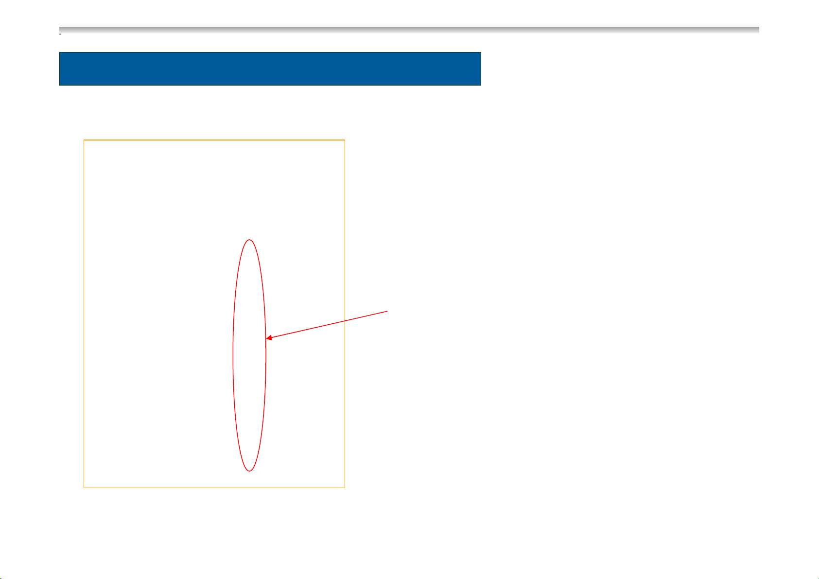
Special Features RM 8xxx
In all single-door RM
8xxx fridges, the
freezing compartment
can be taken out if
needed. This
increases the capacity
as well as the cooling
performance in the
TD S10
cooling compartment.
Page 11
MODELS
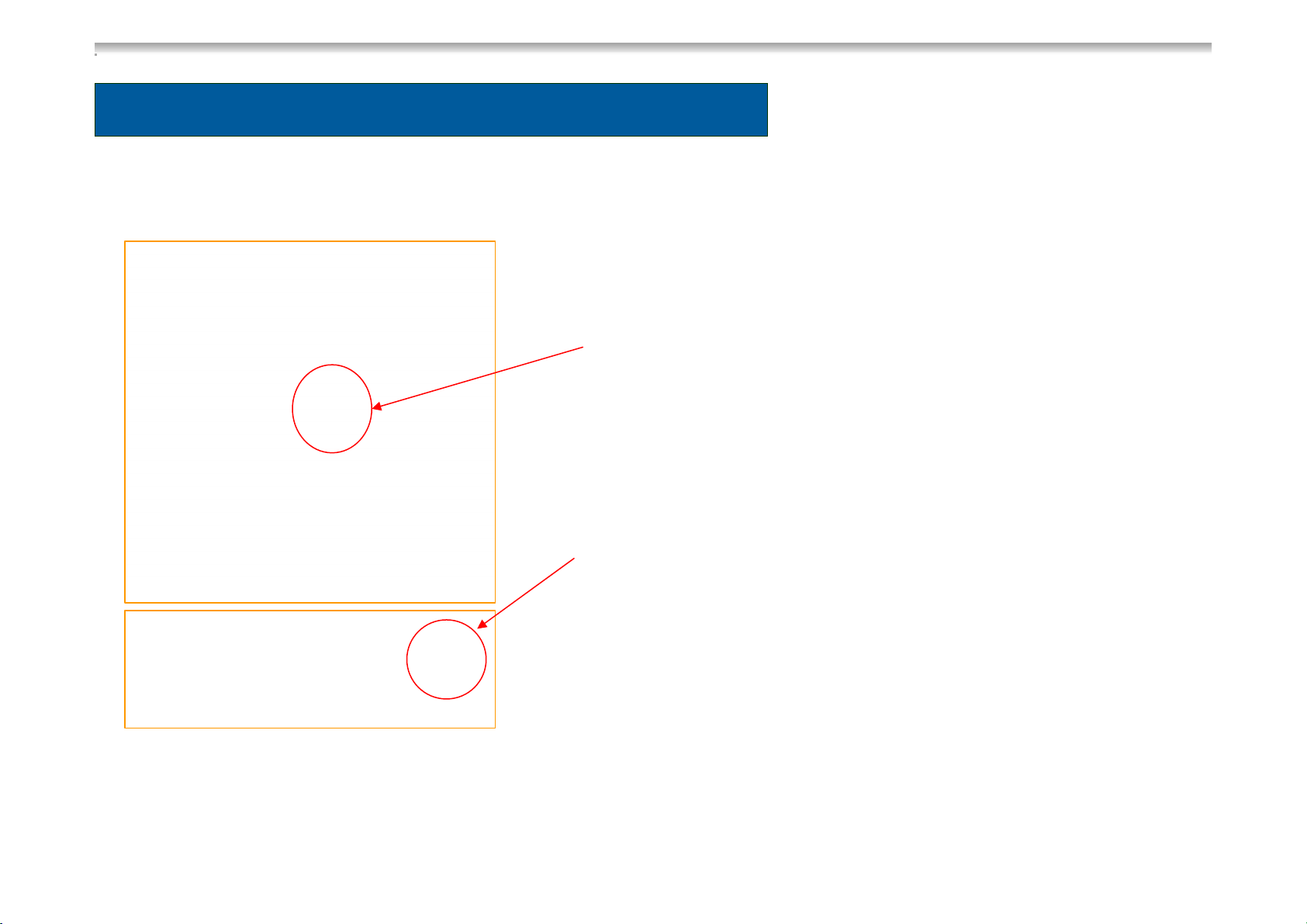
Special Features RM 8xxx
RM 8xxx with
removable
freezer
compartment
TD S11
Locking of freezing compartment
Page 12
MODELS
Special Features RM 8xxx
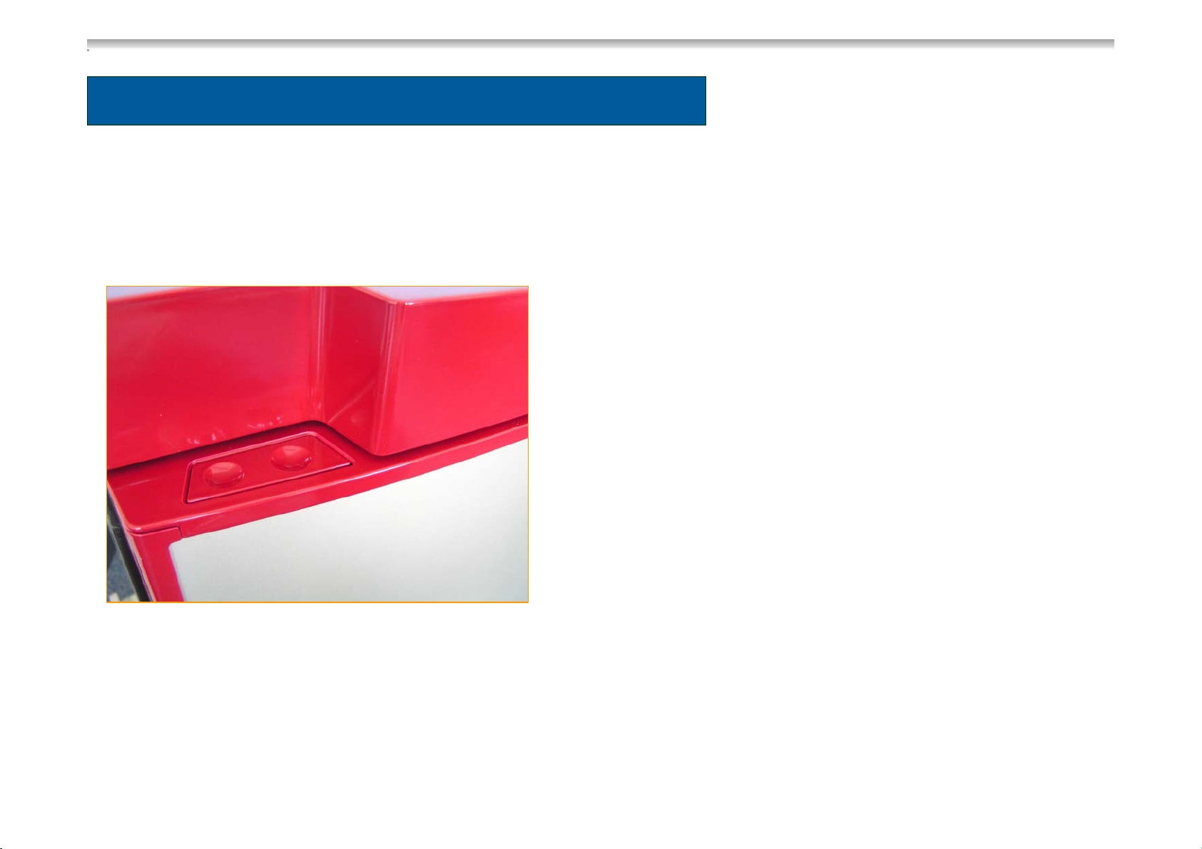
All RM 8xxx fridges have a new door
lock. By pushing the locking button the
door is opened.
Closing the door the locking bar snaps
in and the door is locked. For using the
locking button, the panel is formed
asymmetric (recess on one side). I.e.
changing the door rabbet is not
possible anymore. The rabbet has to
be determined before the fridge is
TD S12
installed.
The product number controls the side
of the door rabbet. Please notify this, if
the door or the fridge is exchanged!
Page 13
MODELS
Special Features RM 8xxx
The locking bar inside the door is fixed with two screws, which are behind a plastic cover. The
gear rods inside the door are not exchangeable. The lock in the fridge is exchangeable. It also
contains the fridge lighting, which was converted into a long-living LED-lighting. The door is
brought into winter position by moving the red hook.
TD S13
Page 14

MODELS
Special Features RM 8xxx
Purchasing an RM 7xxx or
an RM 8xxx, there is the
option of an electrical doorlock. When the fridge door is
closed, it is kept shut by a
magnetic sealing, but not
locked. Starting the engine,
the electronics will
automatically lock the fridge
door, due to the recognition
of the D+ signal. Also with
this kind of door lock,
changing the door rabbet is
TD S14
not possible.
Page 15

MODELS
Special Features RM 8xxx
All RM 8xxx fridges are equipped
with new door hinges made of
metal with a plastic casing
(polystyrene). This hinges are not
screwed onto the housing
anymore, but snap in. Thus it is
not necessary anymore to adjust
the height. Building in the fridge,
please note, that the door hinges
have to be supported. Minimum
TD S15
requirement for the supporting
surface of the lower hinges is the
distance from the housing edge
to the outer edges of the hinges
with 40mm.
Page 16
MODELLE
Special Features RM 8xxx
Changing the decor plate, the door has
not to be demounted anymore. It can be
changed easily:
Loosen the plastic ledge on the locking
side carefully. This ledge is only
snapped in, but not screwed onto the
housing. Then pull out the decor plate
and put in the new one. After this
reattach the plastic ledge.
TD S16
Page 17
MODELS
Special Features RM 8xxx
The operation panel can be loosened with
two screws, when the door is opened. The
electronics at the RM 8xx1 and RM 8xx5 is
screwed into the panel from the inside.
If the fridge is demounted, the operation
panel including the holding device can be
loosened very easily. It is only attached to
TD S17
the housing.
Page 18

MODELS
Special Features RM 8xxx
If the fridge is equipped with a battery igniter, as with the 7xxx – generation, a V85 Gas /
electro fitting and the known energy-selection switch are used. Also, the RM 8xxx fridges are
equipped with a galvanometer, which indicates if the flame is burning. At all single-door fridges
of the 8-series, the main connecting block is positioned on the top of the housing. The
electronics is screwed into the panel.
TD S18
Page 19

MODELS
Special Features RM 8xxx
On the backside of the 8-series
fridges the same components
are used as with the 7xxxGeneration. Cooling unit, gas
valve GV 100, burner control
device P810, burner and
heating elements are identical.
The cooling unit and the
TD S19
components are screwed onto
a metal sheet plate, which is
fixed onto the back side of the
plastic housing.
Page 20

MODELS
Special Features RM 8xxx
The electronics were
completely renewed.
MES AES
Electronics Electronics
Optical differentiation:
a “BEEPER“
Instead of using a
semiconductor, as with
AES III or MES, the new
generation uses a
microprocessor. The AESmodels are equipped with
a 7-segment-display. If an
error occurs, there is an
acoustic signal. There is
no acoustic signal for the
MES-models. All optical
indications are shown with
LED.
TD S20
Page 21

OPERATION
TD S21
Page 22

OPERATION
Interior light
If the door is left opened, the lighting switches off automatically after 2 minutes.
Dimming function of the indications on the operation panel
10 seconds after the button has been pushed for the last time, the indication (LED) switches
into the dim-mode. The dim-mode is reversed by pushing a button. The desired function is
activated by pushing the button again.
TD S22
Page 23

OPERATION
1 2 3 4
Mode on/off
MES
5 6 7
Description of the Display:
1. Pushing the button ON/OFF and modeselection-button longer than 2 seconds
= ON/OFF
Pushing the button <2 Seconds =
Selection next Mode (120V, 12V, GAS,
Auto)
2. LED Fault indication
3. LED Mode-Indication
120 V
12 V
GAS
Temp door
4. 5-step LED-Indication for inner temperature
selection (5 LEDs = max. Setting)
5. LED-Indication for „Door locked“ (only for
electrical lock)
6. Button for temperature selection
7. Button for unlocking the door while driving
(only for electrical lock)
TD S23
Page 24

OPERATION
120V-Operation mode (AC-Mode)
The 120V-operation mode is selected by pushing the button 1 (see TD S23). The button has
to be pushed several times, until the LED next to the Symbol of the power plug lights up.
Detection of undervoltage while operating with 120V
The controlling electronics is equipped with a detection of undervoltage.
Conditions:
- limit value: 103 V AC (min. 101
- The 120V-Relais switches off after
- Switches back from undervoltage mode to normal mode after ca. 20 seconds
- Undervoltage
TD S24
V, max. 105V)
ca. 5 seconds “observation”
fault indication by flashing of display 2 +
3 (see TD
S23)
Page 25

OPERATION
12V-operation mode (DC-Mode)
The 12V-operation mode is selected by pushing the button 1 (see TD S23). The button has
to be pushed several times, until the LED next to the Symbol of the battery lights up
Detection of undervoltage while operating with 12V
The controlling electronics is equipped with a detection of undervoltage.
Conditions:
- Limit value: 10.5 V AC (min. 10.2 V, max. 10.8 V)
- The 12V-Relais switches of after ca 10 minutes „observation“
- Switches back from undervoltage mode to normal mode after ca. 25 minutes
- Undervoltage fault indication by flashing of Display 2 + 3 (see TD S23)
.
TD S25
Page 26

OPERATION
Gas-operation mode
The 12V-operation mode is selected by pushing the button 1 (see TD S23). The button has
to be pushed several times, until the LED next to the Symbol of the Gas lights up or the
(AES-) display indicates GAS.
Ignition while operating with gas.
The controlling electronics initiates max. 3 ignition attempts in the following cycle:
25 sec. ignition, if not ok, 2 min. ventilation break
25 sec. ignition, if not ok, 2 min. ventilation break
25 sec. Ignition, if not ok, FAULT INDICATION by flashing of the fault-LED and the
gas operation LED (see TD S23).
TD S26
Page 27

OPERATION
1 2 3 4
Mode ON/OFF
AES
5
Description of the Display:
1. Pushing the button ON/OFF and Mode-selection-button
longer than 2 seconds = ON/OFF
Pushing the button <2 Seconds = Selection next mode
(120V, 12V, GAS, Auto)
2. LED Fault indication
3. Segment Mode-Indication:
GAS = Gas mode
12 = 12 V DC Mode
120=120 V AC Mode
Selecting the automatic mode, the display shows
AU alternating Gas, 12 or 120 (AU = automatic mode)
Temp door
6 7
4. 5-step LED-Indication for inner temperature
selection (5 LEDs =max. Setting)
5. LED-Indication for „Door locked“ (only for
electrical lock)
6. Button for temperature selection
7. Button for unlocking the door while driving
(only for electrical lock)
TD S27
Page 28

OPERATION
120V-operation mode (manual)
The 12V-operation mode is selected by pushing the button 1 (see TD S27). The button has
to be pushed several times, until the 7-segment-display indicates 120.
Detection of undervoltage while operating with 120V
The controlling electronics is equipped with a detection of undervoltage.
Conditions:
- Limit value: 103 V AC (min. 101 V, max. 105 V)
-120V-Relais switches off after ca. 5 seconds “observation”
- Switches back from undervoltage mode to normal mode after ca. 20 seconds
- Undervoltage fault indication by flashing of display 2 + 3 and acoustic signal (see TD S27).
TD S28
Page 29

OPERATION
12V- operation mode (manual)
The 12V-operation mode is selected by pushing the button 1 (see TD S27). The button has
to be pushed several times, until the 7-segment-display indicates 12V. D+ or S+ is not taken
into account in the manual mode.
Detection of undervoltage while operating with 12V
The controlling electronics is equipped with a detection of undervoltage.
Conditions:
- Limit value: 10.5 V AC (min. 10.2 V, max. 10.8 V)
- 12V-Relais switches off after ca. 10 minutes „observation“
- Switches back from undervoltage mode to normal mode after ca. 25 minutes
- undervoltage fault indication by flashing of display 2 + 3 and acoustic signal (see TD S27).
TD S29
Page 30

OPERATION
Gas-operation mode (manual)
The gas operation mode is selected by pushing the button 1 (see TD S27). The button has
to be pushed several times, until the 7-Segment display indicates GAS.
Ignition while operating with gas
The controlling electronics initiates max. 3 ignition attempts in the following cycle:
25 sec. ignition, if not ok, 2 min. ventilation break,
25 sec. ignition, if not ok, 2 min. ventilation break,
25 sec. ignition, if not ok, FAULT INDICATION by flashing of the Fault-LED and the
7-segment-display (see TD S27).
TD S30
Page 31

OPERATION
Automatic Mode
The automatic mode is selected by pushing the button 1 (see TD S27). The button has to be
pushed several times, until the 7-segment display indicates AU. The display switches from
AU to the current energy mode every 10 seconds.
-Priority
12V-Solar 120V 12V (D+) Gas
- Refueling stop of 15 minutes while operating in Auto-12V-Mode (i.e. the electronics system
switches into gas mode only after 15 minutes). During this time the appliances is in
- Recognition of undervoltage as in 120V-mode (also active while D + signal is available)
TD S31
stand-by-operation mode and only the AU-LED lights up.
Page 32

COMPONENTS
TD S32
Page 33

COMPONENTS
Electronics POWER MODULE MES Contacts
X 105 X 114 X 108 X 110 X 111 X 109 X 102 X 101
X105 = 12 V Supply / - Wiring Recognition of heating element
X114 = Reed switch or alt. electr. lock
Fuse 1A
(250V)
Fuse for
burner
control
device
Connection
to Display
X108 = Temperature sensor (NTC)
X110 = Connection burner control device (+/-, failure)
X111 = alt. 2. electr. Lock or reed switch
X109 = Lighting
J4/J5 = Frame heating
J1 = +12 V IN for heating element
J2 = +12 V Heating element
X102 = Heating element mains power
X101 = mains power inlet
J1/ J2J4 / J5
TD S33
Page 34

COMPONENTS
Electronics POWER MODULE AES Contacts
X 105 X 114 X 108 X 110 X 111 X 109X 106
Fuse 1A
(250V)
X105 = 12 V Supply / - Wiring
Recognition of heating element
X114 = Reed switch or alt. electr. lock
X108 = Temperature sensor (NTC)
X110 = Connection to burner control device (+/-, failure)
X111 = alt. 2. electr. Locks or reed switch
RF Module for RMCD
remote control
Connection to
Display
X106 = D+/Solar
X109 = Interior light
J4/J5 = Frame heating
J1 = +12 V IN for heating element
J2 = +12 V Heating element
X102 = Heating element mains power
X101 = Mains power inlet
J4 / J5 J1/ J2
X 102 X 101
Beeper
TD S34
Page 35

COMPONENTS
Burner Control Device P810
includes
Igniter ( 20-30 sec.)
Flame control and
Flame failure device
Gas valve control
(stops ignition and gas input in
case of gas fault)
Power supply : approx. 1.3V
TD S35
Page 36

COMPONENTS
Gas (Safety)-Valve GV100
includes
2 serial mounted gas valves
Power supply: approx. 1.3V - 1.5V per
valve (if switched on approx. 0,7V -09V)
TD S36
Page 37

COMPONENTS
Gas Burner Device
Already installed
Igniting electrode (1)
Ionization electrode (2)
and ground contact (3) on
burner chassis
2
3
1
TD S37
Page 38

COMPONENTS
Temperature sensor (NTC)
Installed at lower reevaporator
All operation modes (DC/AC/GAS)
are controlled thermostatically.
TD S38
Page 39

INSTALLATION
TD S39
Page 40

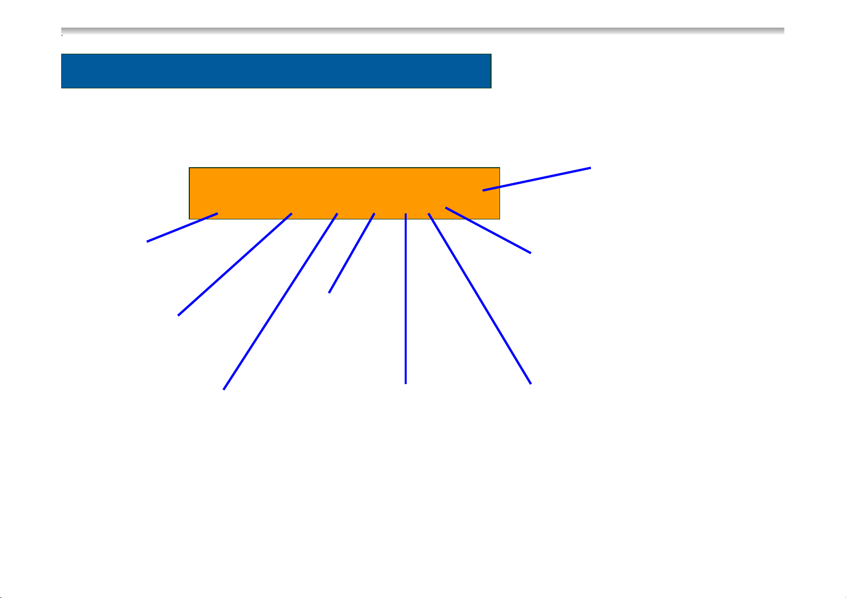
INSTALLATIONINSTALLATION
Scheme of connecting points
120V-wire – connection
to electronics
Connection power supply 12VDC
D+ and S+ Signal
12VDC Power supply
Heating element
Gas supply
TD S40
Page 41

INSTALLATION
Electrical Installation
First of all, please note the INSTALLATION INSTRUCTIONS.
Some important points:
Power line connection
protection with a 2A fuse
Battery connection
protection with a 16A fuse
The electric circuit of the 12V-heating element has to be switched via an appropriate relay,
so the heating element is not supplied anymore, after the engine has been turned off.
The electronics has to be permanently attached to 12V, which is not interrupted, turning off
the engine.
TD S41
Page 42

INSTALLATIONINSTALLATION
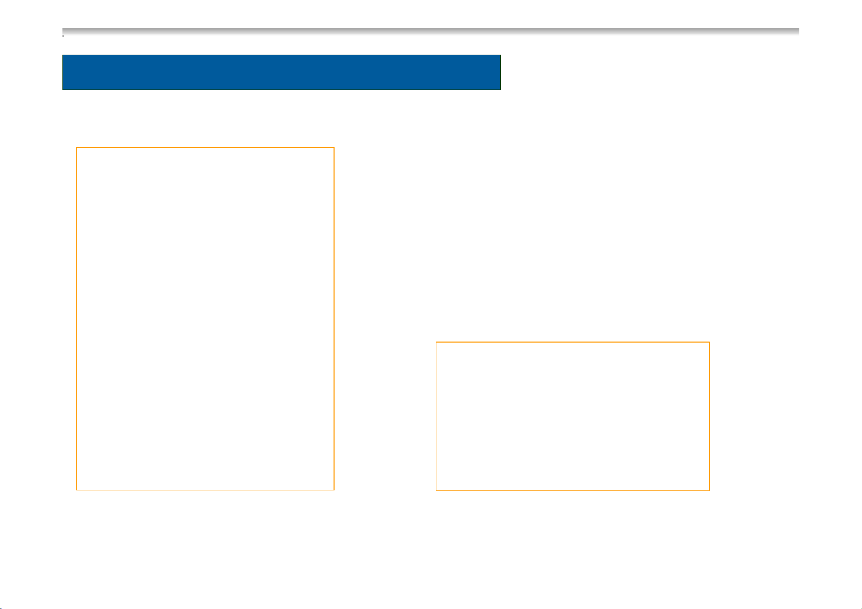
Electrical Installation
Terminal block AES-Model
1 black: - cable
12V-permantent connection for electronics
2 violet: + cable
12V-permanent connection for electronics
3 bl: D+ cable to contact X106 on the
electronics
4 wt: S+ cable to contact X106 on the
electronics
123456
5 white: -cable for 12V heating element
6 red: + cable for 12V heating element via starter
lock and 16A fuse
At the terminal strip of the MES-models, the terminals
3 + 4 are not used.
TD S42
Page 43

INSTALLATIONINSTALLATION
Electrical Installation
TD S43
Page 44

INSTALLATIONINSTALLATION
Electrical Installation
TD S44
Page 45

INSTALLATION
Gas installation
First of all, please note the information of the INSTALLATION INSTRUCTIONS.
2
The gas connection to the appliance has to be done with a
cutting ring connection L8, DIN 2353-ST acc. to EN 1949
(e.g.. Ermeto).
Burner control device (1)
Gas valve (2)
1
Gas connection (3)
TD S45
AB
3
4
Gas tube to the burner (4)
A (max. torque 10Nm ) and B (max. torque 20 Nm) are
preinstalled pipes
Page 46

SERVICE + MAINTENANCE
TD S46
Page 47

INSTALLATIONSERVICE + MAINTENANCE
Some information
Gas Valve GV100
Masse
This component includes two serial mounted gas
valves (as part of flame failure device).
Power supply : approx. 1.3V - 1.5V per valve
Power supply : approx. 0,7V - 0,9V per valve
(switched on gas mode)
Inductive resistance : per valve ca. 28,5 Ohm
Measuring points: Voltage and Resistance
Valve 1 : Pin 1 - Ground (Housing)
Valve 2 : Pin 2 - Ground (Housing)
1
2
TD S47
Page 48

INSTALLATIONSERVICE + MAINTENANCE
Some information
Burner Control Device P810
Power Supply: ca. 1.3V
Measuring points: Flat plug connection
between Pin 2 and Pin 3.
1
2
Cable to Ignition plug : 1
Cable to ionization plug : 2
Exchanging the cables is not possible, as they have different dimensions.
TD S48
Page 49

INSTALLATIONSERVICE + MAINTENANCE
Some information
Temperature Sensor (NTC)
Table of resistance
°
Temperature
0/32 27.7
5/41 22.29
10/50 18.07
15/59 14.74
20/68 12.11
25/77 10.00
C/F Resistance kOhm
Measuring Point: Electronics
loosen contact X108
Cable white / brown
When the sensor is defect, the fridge will operate permanently.
TD S49
Page 50

INSTALLATIONSERVICE + MAINTENANCE
Some information
Interior light and door lock
The Interior light and the door lock are
unit, which is exchanged completely in
case of a defect.
The transparent cover is not included,
but a separate part.
After removing the cover, the lighting
housing can be dismantled.
TD S50
Page 51

INSTALLATIONSERVICE + MAINTENANCE
Some information
Cleaning of burner
The burner and the chimney must be
cleaned regularly, at least one time a
year.
If auto gas is used, Dometic
recommends a maintenance every half
year, as the contamination risk of the
burner is higher, due to the burning of
the auto gas.
TD S51
Page 52

SERVICE + MAINTENANCE
Service Mode AES
The Service Mode is activated by keeping pressed down the temperature button
and switching on the main button.
After this the 7-Segment-Display shows „1“. By pushing the temperature button,
the different test-steps can be activated:
1 = activates 120 V heating element (120V must be available)
2 = activates 120V relay (120V has not to be necessarily available)
3 = activates 12 V heating element (D+ and 12V supply has to be available)
4 = Intern test step (is not indicated)
5 = activates burner control device – output (Gas operation)
6 = activates frame heating
7 = activates interior lights (Except for electrical lock)
TD S52
52
Page 53

SERVICE + MAINTENANCE
Service Mode AES
8 = Intern test step (is not indicated)
9 = Recognizing electrical lock or reed switch
10 = activates all 7 segment-components one after the other
11 = activates all LED´s
Exiting the diagnosis mode: Push „mode“ button or wait for 10 minutes.
TD S53
53
Page 54

SERVICE + MAINTENANCE
Controlling the interior light via reed switch
The AES-Electronics uses the X114 and X111 as well for controlling the reed
switch as well as the electrical lock.
The electronics will recognize the application of a reed switch, following the
below steps:
1. Choose step 9 in the service mode
2. Open the door
3. Close the door (reed switch will be recognized)
4. Continue service mode (push button 6)
The interior light will now be controlled via the reed switch.
Basically the electronics are defined with “recognizing Reed switch”.
TD S54
54
Page 55

SERVICE + MAINTENANCE
Electrical door lock
Optionally, 2 electrical door locks can be controlled.
They are connected to X111 and X114 (it does not matter in which order; X111 and X114 are
equivalent)
In the service mode the electronics will recognize the locks, following the below steps:
1. Open the door(s)
2. Choose step 9 in the service mode
3. Close door(s) (Door locks will be recognized)
4. Activate D+
5. Continue Service mode (push button 6)
The locked door is indicated with LED 5 and can be unlocked by pushing the button 7.
If you have 2 electrical door locks, LED 5 will flash, if one lock is not locked.
TD S55
55
Page 56

SERVICE + MAINTENANCE
AESFailureNo.
No 120V, respective under 195V (AC Mode)1
No 12V, respective under 10,5V (DC Mode)2
Ignition without success (Gas Mode)3
NTC sensor defect4
120V heating element defect*5
12V heating element defect*6
Failure LED 2 and „120“ (3) flash
Acoustic Signal
Failure LED 2 and „12“ (3) flash
Acoustic Signal
Failure LED 2 and „GAS“ (3) flash
Acoustic Signal
Failure LED 2 and Temp.-LEDs (4) flash
Acoustic Signal
Failure LED 2 and Indicator 4 „HE 1“ flash
Acoustic Signal
Failure LED 2 and Indicator 4 „HE 2“ flash
Acoustic Signal
TD S56
Acoustic SignalDoor opened (longer than 2min.)7
56
Page 57

SERVICE + MAINTENANCE
*Sequence for recognizing „Heating element defect“:
Conditions: Interior temperature >18/64°C/F, corresponding relay is switched on
(120V or 12V), door has to be closed for longer than 5 minutes.
Temperature of reevaporater (a) is recorded
After 2 hours, the temperature (b) is recorded again, if the fridge is in the
same mode
If the temperature difference a-b < 3 °K, the corresponding heating element
error will be indicated
TD S57
57
Page 58

SERVICE + MAINTENANCE
Service Mode MES
The Service Mode is activated by keeping pressed down the temperature button
and switching on the main button.
After this all 3 mode-LEDs (3) light up.
By pushing the temperature button (6), the different test-steps can be activated,
test steps 1-6 are indicated by the temperature LEDs (4)
1 = activates 120 V heating element (120V must be available)
2 = activates 120V relay (120V has not to be necessarily available)
3 = activates 12 V heating element (12V has to be available)
4 = activates burner control device – output (Gas operation)
5 = activates frame heating
6 = activates interior lights (For fridges without electrical lock)
TD S58
58
Page 59

SERVICE + MAINTENANCE
Service Mode MES
7 = Recognition sequence (Reed switch or electrical lock)
8 = activates temperature LEDs (4)
9 = activates lock and failure LED (2) + (5)
Exiting the diagnosis mode: Push the „mode“ button or wait for 10 minutes.
TD S59
59
Page 60

SERVICE + MAINTENANCE
Controlling the interior light via reed switch
The MES-Electronics uses the X114 and X111 as well for controlling the reed
switch as well as the electrical lock.
In the Service mode, the electronics will recognize the application of a reed
switch, following the below steps:
1. Choose step 7 in the service mode
2. Deactivate D+; open the door
3. Push temperature button (6)
4. Close the door (reed switch will be recognized)
5. Continue service mode (push button 6)
The interior light will now be controlled via the reed switch.
Basically the electronics are defined with “recognizing Reed switch”.
TD S60
60
Page 61

SERVICE + MAINTENANCE
Electrical door lock
Optionally, max. two electrical door locks can be controlled. They are connected to X111
and X114 (Notify, that if there is only one lock this has to be connected to X111).
In the service mode the electronics will recognize the locks following the below steps:
1. Open the door(s)
2. Choose step 7 in the service mode
3. Close the door(s)
4. Deactivate D+
5. Continue Service mode with step 6
The locked door will be indicated via LED 5, and can be unlocked by pushing button 7.
If you have 2 electrical door locks, LED 5 will flash, if one lock is not locked.
TD S61
61
Page 62

SERVICE + MAINTENANCE
Error messages
AESErrorNo.
1
Mode)
4
5
120V heating element or cooling unit
defect*
12V heating element or cooling unit
defect*
Failure LED 2 and LED 3 (DC Mode) flash No 12V, respective under 10,5V (DC
Failure LED 2 and LED 3 (Gas Mode) flashIgnition without success (Gas Mode)2
Failure LED 2 and temperature – LEDs 4 flashNTC sensor defect3
Failure LED 2, LED 3 (AC Mode) and
temperature – LEDs 4 flash
Failure LED 2, LED 3 (DC Mode) and
temperature – LEDs 4 flash
TD S62
62
Page 63

SERVICE + MAINTENANCE
*Sequence for recognizing „heating element defect“:
Conditions: Interior temperature >18/64°C/F, corresponding relay is switched on
(120V or 12V), door has to be closed for longer than 5 minutes
Temperature of reevaporator (a) is recorded
After 2 hours, the temperature (b) is recorded again, if the fridge is in the
same mode.
If the temperature difference a-b < 3 °K, the corresponding heating element
error will be indicated.
TD S63
63
Page 64

INSTALLATION
DOMETIC GMBH
DOMETIC GMBH
TECHNISCHE DOKUMENTATION
TECHNISCHE DOKUMENTATION
IN DER STEINWIESE 16
IN DER STEINWIESE 16
57074 SIEGEN
DD--57074 SIEGEN
GERMANY
GERMANY
www.dometic.com
www.dometic.com
Page 65

This manual has been provided courtesy of
DARREN KOEPP - OWNER, MY RV WORKS, INC.
www.myrvworks.com
You can find more RV service manuals here:
www.myrvworks.com/manuals
My RV Works, Inc.
Over the years of running a mobile RV repair service, having a dedicated place
to access service manuals for all the different appliances and components
found on RVs was something that I always had a desire to create.
I hope this resource makes your RV repairs easier, as it has mine, but please
be careful and follow proper safety practices when attempting to repair
your own RV.
If in doubt, please consult with a professional RV technician!
All service manuals provided on www.myrvworks.com are believed to be
released for distribution and/or in the public domain.
 Loading...