

Page 1
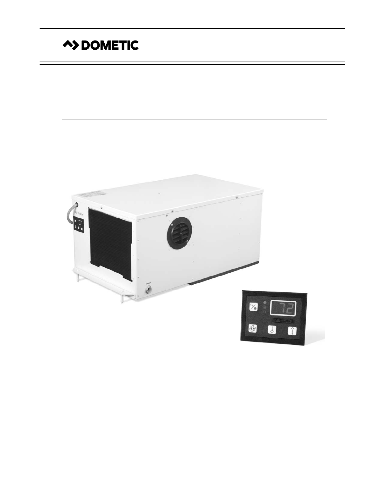
Radome Environmental Control Unit
With Passport I/O Compact Digital Display
INSTALLATION, OPERATION & MAINTENANCE MANUAL
Dometic Corporation
Rev. 20170601
L-2283 English
Part Number 297200038
COPYRIGHT © 1997-2017 Dometic Corporation. All Rights Reserved.
No part of this publication may be reproduced, translated, stored in a retrieval system, or transmitted in any form or by any means
electronic, mechanical, photocopying,recording or otherwise without prior written consent by Dometic Corporation. Every precaution
has been taken in the preparation of this manual to insure its accuracy. However , Dometic Corporation assumes no responsibility for
errors and omission. Neither is any liability assumed for damages resulting from the use of this product and information contained
herein.
Page 2

Table of Contents
INTRODUCTION . . . . . . . . . . . . . . . . . . . . . . . . . . . . . . . 1
T
HIS MANUAL . . . . . . . . . . . . . . . . . . . . . . . . . . . . . . 1
UNPACKING AND INSPECTION . . . . . . . . . . . . . . . . . . . 1
H
OW IT WORKS . . . . . . . . . . . . . . . . . . . . . . . . . . . . . 1
S
AFETY CONSIDERATIONS . . . . . . . . . . . . . . . . . . . . . 1
WARNINGS AND NOTICES . . . . . . . . . . . . . . . . . . . . . . 2
INSTALLATION PROCEDURES . . . . . . . . . . . . . . . . . . 3
INTERNAL UNITS . . . . . . . . . . . . . . . . . . . . . . . . . . . . 3
EXTERNAL UNITS . . . . . . . . . . . . . . . . . . . . . . . . . . . . 3
E
LECTRICAL . . . . . . . . . . . . . . . . . . . . . . . . . . . . . . . . 3
THE DIGITAL CONTROL . . . . . . . . . . . . . . . . . . . . . . . . 3
NDICATORS AND BUTTONS . . . . . . . . . . . . . . . . . . . . 3
I
Cool Mode Indicator . . . . . . . . . . . . . . . . . . . . . 3
Fan Indicator . . . . . . . . . . . . . . . . . . . . . . . . . . . 4
Heat Mode Indicator . . . . . . . . . . . . . . . . . . . . . 4
Digital Display . . . . . . . . . . . . . . . . . . . . . . . . . . 4
Set Point . . . . . . . . . . . . . . . . . . . . . . . . . . . . . . 4
Air Sensor . . . . . . . . . . . . . . . . . . . . . . . . . . . . . 4
Fan Button . . . . . . . . . . . . . . . . . . . . . . . . . . . . 4
Power . . . . . . . . . . . . . . . . . . . . . . . . . . . . . . . . 4
M
ODES OF OPERATION . . . . . . . . . . . . . . . . . . . . . . . 5
Off Mode . . . . . . . . . . . . . . . . . . . . . . . . . . . . . . 5
On Mode . . . . . . . . . . . . . . . . . . . . . . . . . . . . . . 5
Cool Mode . . . . . . . . . . . . . . . . . . . . . . . . . . . . 5
Heat Mode . . . . . . . . . . . . . . . . . . . . . . . . . . . . 5
Automatic Mode . . . . . . . . . . . . . . . . . . . . . . . . 5
Moisture Mode . . . . . . . . . . . . . . . . . . . . . . . . . 5
Fan Modes . . . . . . . . . . . . . . . . . . . . . . . . . . . . 5
Automatic Fan Mode . . . . . . . . . . . . . . . . . 5
Manual Fan Mode. . . . . . . . . . . . . . . . . . . . 5
Fan-Only Mode. . . . . . . . . . . . . . . . . . . . . . 5
Cycled or Continuous Fan Operation . . . . . 5
Program Mode . . . . . . . . . . . . . . . . . . . . . . . . . 5
Important Programming Notes To Installer
and End User . . . . . . . . . . . . . . . . . . . . . . . 6
Using Program Mode . . . . . . . . . . . . . . . . . 6
Programming . . . . . . . . . . . . . . . . . . . . . . . 7
Programmable Parameters . . . . . . . . . . . . 7
OPERATION . . . . . . . . . . . . . . . . . . . . . . . . . . . . . . . . . 10
TROUBLESHOOTING GUIDELINES . . . . . . . . . . . . . . 11
MAINTENANCE . . . . . . . . . . . . . . . . . . . . . . . . . . . . . . . 12
C
ONDENSER COIL . . . . . . . . . . . . . . . . . . . . . . . . . . . 12
R
ETURN-AIR FILTERS . . . . . . . . . . . . . . . . . . . . . . . . 12
DIAGRAMS . . . . . . . . . . . . . . . . . . . . . . . . . . . . . . . . . . 12
W
IRING & PRODUCT DIAGRAMS . . . . . . . . . . . . . . . . . 12
T
EMPLATE FOR INTERIOR UNIT . . . . . . . . . . . . . . . . . 16
MOUNTING DIAGRAMS . . . . . . . . . . . . . . . . . . . . . . . . 17
L-2283 ENGLISH
Page 3

Radome Environmental Control Un it INTRODUCTION
INTRODUCTION
Congratulations on the purchase of your Radome Environmental Control Unit (ECU) air conditioning system. The Radome
ECU is a self-contained direct-expansion air conditioner designed for custom applications and features:
• High-efficiency rotary compressor
• Raised lance fin evaporator coil
• Pre-charged and pre-wired systems for easy connections
• ChargeGuard® ensured environmental protection and system integrity
The Passport I/O Compact microprocessor-based digital control included with this unit offers the most technologically advance
design and is specifically made for the unique requirements of the Radome ECU system. The control features:
• Non-volatile memory
• Low voltage display panel
• Faceplate air sensor for accurate temperatu re co ntrol
• LED temperature displayed in Fahrenheit or Celsius
• Compressor pressure protection
THIS MANUAL
This manual is intended to provide the information necessary to ensure proper installation, operation, and maintenance of the
unit. Improper installation or misunderstood operating procedures can result in unsatisfactory performance and/or premature
failure of the unit. Before proceeding, read this manual completely.
The Radome ECU is covered under the warranty policy contained in this manual. In the interest of product improvement,
specifications and designs herein are subject to change without prior notice.
UNPACKING AND INSPECTION
When you receive the equipment, carefully check all items against the packing list to ensure all cartons were received. Move
units in the normal “up” orientation as indicated by the arrows on each carton. Examine cartons for shipping damage, removing
the units from the cartons if necessary. If the unit is damaged, the carrier should make the proper notation on the delivery receipt
acknowledging the damage.
HOW IT WORKS
The Radome ECU consists of four main components and a refrigerant gas circulating through the system. The blower draws
warm interior air across the fins of the evaporator where the heat from the air is transferred to the refrigerant in the evaporator
coil. As the refrigerant absorbs heat from the warm air, it evaporates from a liquid into a gas. The compressor then compresses
the refrigerant gas and pumps it through the outer tube in the condenser coil. The heat from the refrigerant is exchanged to the
condenser and discharged out of the dome. The liquid refrigerant is then passed through the evaporator coil and the cycle
repeats.
Through this heat-transfer process, heat is removed from the interior dome and its temperature decreases. The cooled air blows
into the dome out of the supply-air grille which is mounted on the unit.
If heating is needed in the dome instead of cooling, the electric heater option must be installed and the system programmed
accordingly (see “Heat Mode” on page 5).
SAFETY CONSIDERATIONS
Installation and servicing of this system can be hazardous due to system pressure and electrical components. When working on
this equipment:
• Always observe precautions described in the literature and on tags and labels attached to the unit.
• Follow all safety codes.
• Wear safety glasses and work gloves and place a fire extinguisher close to the work area.
L-2283 ENGLISH 1
Page 4
INTRODUCTION Radome Environmental Control Unit
WARNINGS AND NOTICES
WARNING
This manual contains essential safety information concerning the safe and proper installation, operation, and
maintenance of your Radome ECU. It is very important that you read and understand the contents of this manual
thoroughly before installing or using the equipment. You should keep this manual on your boat for future reference.
Failure to follow Dometic approved installation, start-up, operation, and troubleshooting procedures will void the
warranty. If there are any statements in this manual that you do not understand, contact your local dealer for
assistance or the Dometic Marine Service Department:
• Phone: +1 804-746-1313 or +1 954-973-2477 (8AM - 5PM US Eastern Time)
• Fax: +1 804-746-7248 or +1 954-979-4414
DANGER
ELECTRICAL SHOCK HAZARD. DISCONNECT VOLTAGE AT MAIN PANEL OR POWER SOURCE BEFORE OPENING
ANY COVER. FAILURE TO COMPLY MAY RESULT IN INJURY OR DEATH.
DANGER
The equipment referenced in this manual operates with compressed refrigerant at high pressures. Proper care must
be taken during installation, operation, and servicing to prevent injury or loss of life due to improper procedures.
DANGER
This equipment is not ignition protected per CFR 183.410 and may not be installed in areas that may be exposed to
flammable gases. Do not install in spaces containing gasoline engines, tanks, LPG/CPG cylinders, regulators, valves
or fuel line fittings. Failure to comply may result in injury or death.
WARNING
T o minimize the hazard of electrical shock and personal injury , this component must be effectively grounded. Refer to
the installation gu ide li n es for further information.
NOTICE
Some equipment may be shipped with specific installation sheets or wiring diagrams that may supersede the
information located in this manual. Dometic reserves the right to update or change any information located herein at
any time and without prior notice.
NOTICE
Contains R-417A fluorinated greenhouse gas in hermetically sealed equipment. Refer to the conden sing unit's product
data plate label for quantity of refrigerant shown in weight, global warming potential (GWP), and equivalent tonnes of
CO2 (tCO2e). Any refrigerant added should be noted on unit label.
2 L-2283 ENGLISH
Page 5

Radome Environmental Control Un it INSTALLATION PROCEDURES
INSTALLATION PROCEDURES
This section covers the installation procedures for internal and external Radome ECU systems. Read the manual completely
before attempting to install any equipment.
INTERNAL UNITS
1. If you are installing an internal Radome ECU, select a location in the dome that will not interfere with the antenna.
2. Internal units must be accessible and have a clear area below the dome for condenser openings. There must be
adequate space for air flow underneath the dome pedestal.
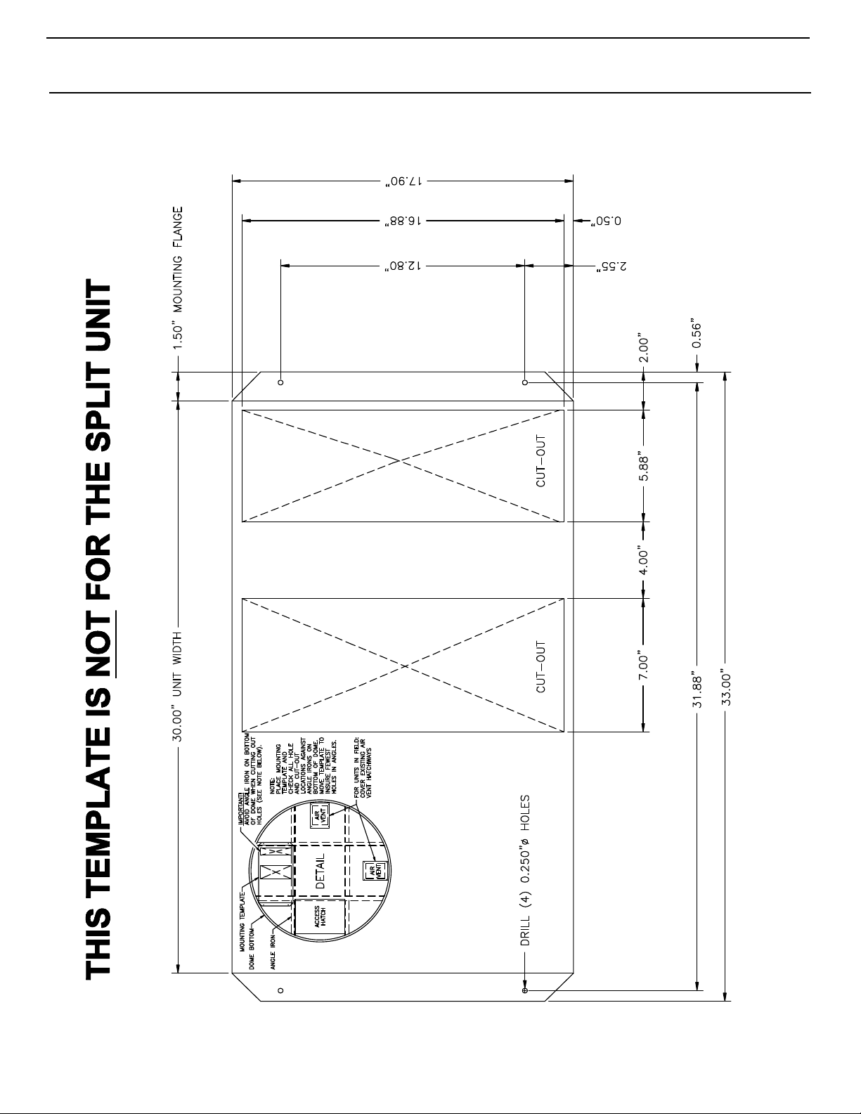
3. Use cutout template (see “Template For Interior Unit” on page 16) to mark and then cut openings in dome floor. Drill
holes for mounting as per template.
4. Ensure that intake and discharge condenser air streams are separated with a divider so that air does not short-cycle
from exhaust to intake.
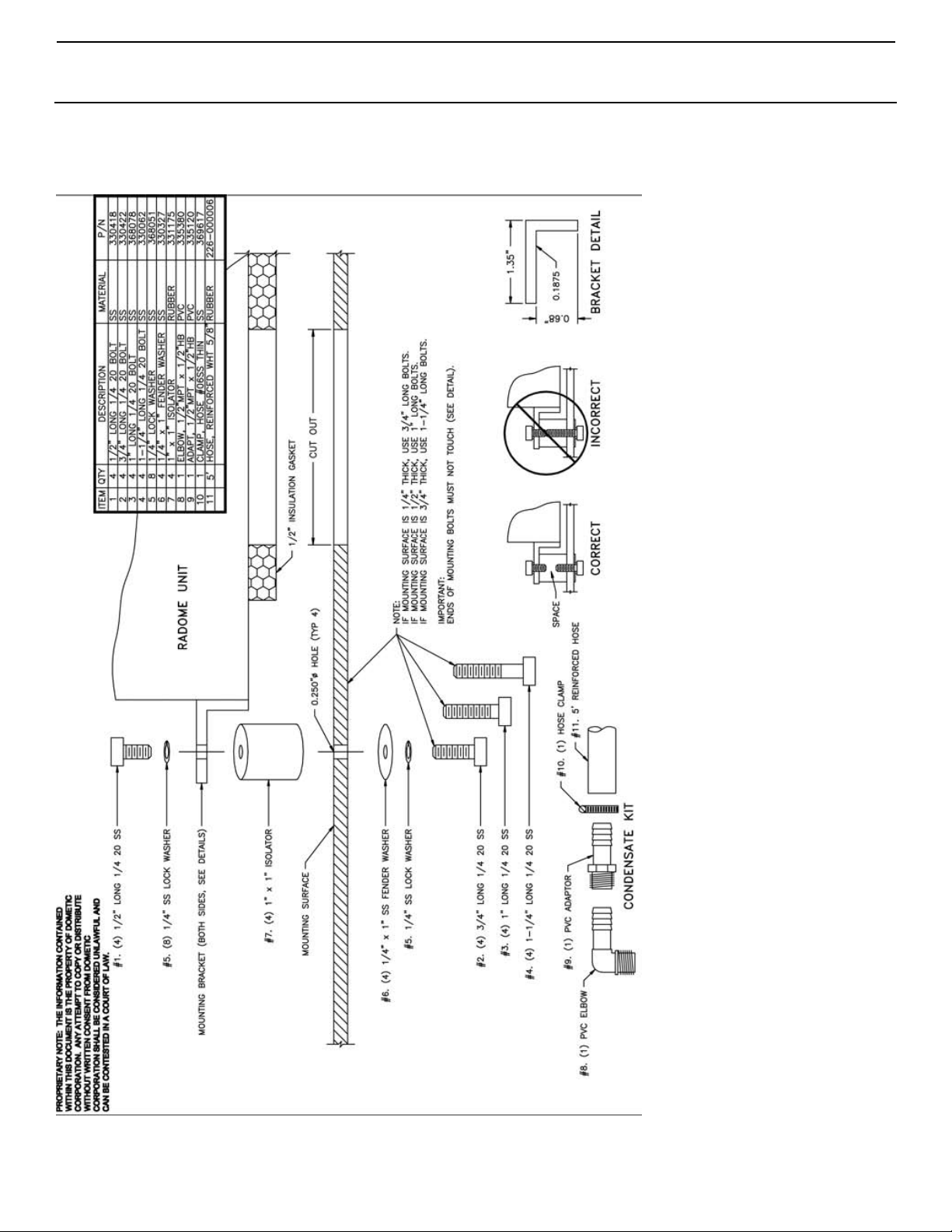
5. Position the Radome ECU over openings and fasten unit using hardware provided. Ensure foam seals are tight
between ECU and mounting surface and there are no leaks from outside.
6. Make electrical connections as described in “Electrical” below.
7. Use a diverter to position cool-air discharge away from the antenna.
EXTERNAL UNITS
1. If you are installing an external Radome ECU, select a location near the dome to keep evaporator ducting as short and
straight as possible. Ensure that condenser openings can be clear from obstacles.
2. Mount unit to deck using hardware provided.
3. Install evaporator return and supply ducting to dome. Ensure that ducting is taught, secure, and as straight as possible
to minimize bends. Use insulated ducting to reduce heat gain to dome.
4. Make electrical connections as described in “Electrical” below.
5. Position the Passport I/O Compact digital display inside the dome in a location that will sense dome temperature. To
avoid short-cycling, do not place near the supply-air stream into dome .
6. Use a diverter to position cool-air discharge away from the antenna.
ELECTRICAL
1. T urn off the A/C’ s power-supply circuit breaker before opening electric box. Each A/C unit requires its own
dedicated circuit breaker. Use the correct size circuit breaker to protect the system as specified on the Radome ECU’s
data plate label.
2. Remove the electric box panel to access the circuit board and the terminal strip mounted on it.
3. The terminal strip is labeled for proper connections of the electrical supply and ground wires (see “Wiring & Product
Diagrams” on page 12). Make these connections. All connections shall be made with solderless terminals.
THE DIGITAL CONTROL
The Passport I/O Compact is a digital control that displays current temperature and operating mode, and is also used for making
programming changes that affect system operation.
The control has nonvolatile memory requiring no batteries or backup power. When power is lost, the operating parameters are
retained indefinitely. When power is restored, the control resumes operation as last programmed.
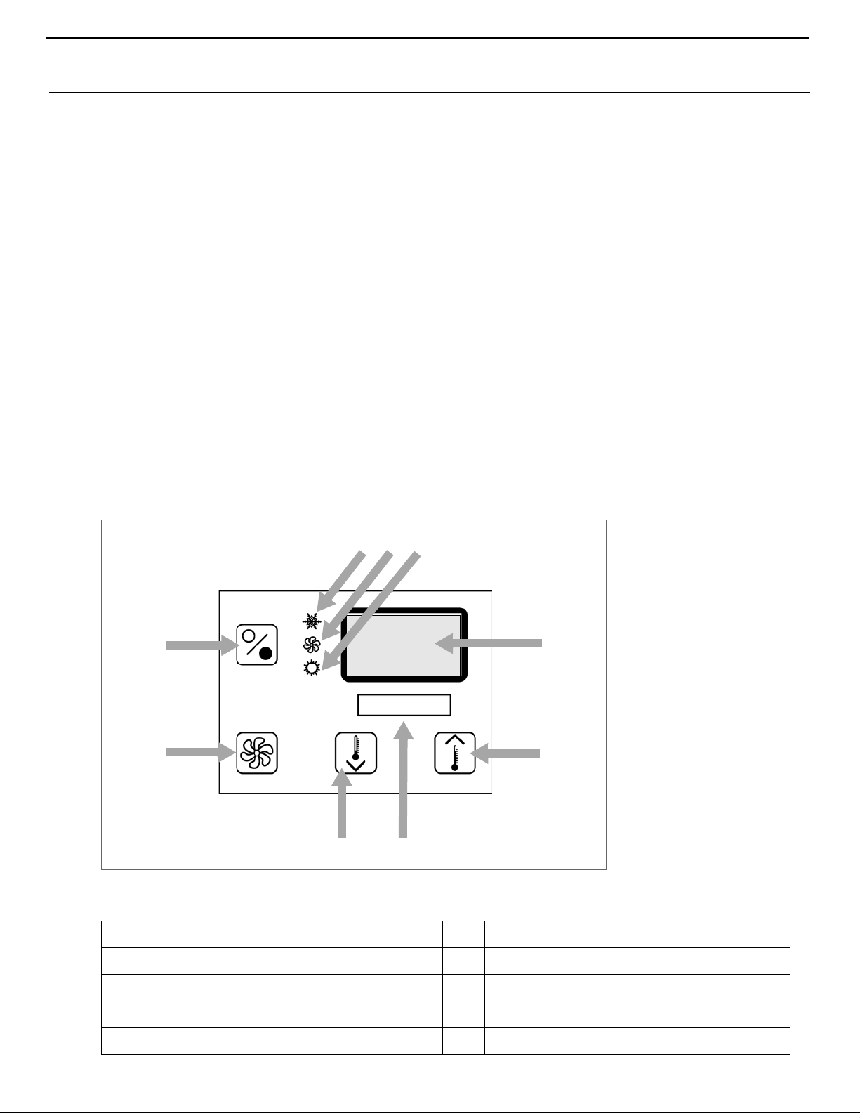
See Figure 1 and Table 1 on page 4 to identify all parts of the control.
INDICATORS AND BUTTONS
COOL MODE INDICATOR
Lights when the compressor is running in Cool Mode or in Automatic Mode while cooling. Automatic Mode is only used if
optional electric heat is installed.
L-2283 ENGLISH 3
Page 6
THE DIGITAL CONTROL Radome Environmental Control Unit
123
4
5
67
8
9
FAN INDICATOR
Lights when the fan is running.
HEAT MODE INDICATOR
Lights when the electric heater is running or in Automatic Mode while heating. Automatic Mode is only used if optional electric
heat is installed.
DIGITAL DISPLAY
Shows current temperature and is also used to view and set program parameters.
SET POINT
Press the Up or Down button to set the desired room temperature. To view the set point, momentarily press and release the Up
or Down button. The Radome ECU set point is 85°F.
AIR SENSOR
Dome temperature is detected by the air sensor on the face plate.
FAN BUTTON
Not used on Radome ECU.
POWER
Press the Power button once to engage the system. The display is blank when the system is off and indicates current room
temperature when the system is on.
Figure 1: Passport I/O Compact Display Panel and Indicators
Table 1: Passport I/O Display - Diagram Legend
1
Cool Mode indicator
2
Fan indicator
3
4 L-2283 ENGLISH
Heat Mode indicator (only with electric heat option)
4
Digital display
5
Up button - Raise temperature set point
6
7
8
9
Temperature sensor
Down button - Lower temperature set point
Fan button (Not used on Radome ECU)
Power button
Page 7
Radome Environmental Control Un it THE DIGITAL CONTROL
MODES OF OPERATION
OFF MODE
When the control is in Off Mode, all control outputs are turned off. Program parameters and user settings are saved in
nonvolatile memory. The Program Mode can only be accessed from the Off Mode.
ON MODE
When the control is in On Mode, power is supplied to the appropriate outputs and the display indicates the current state of
operation. The operating and program parameters resume b ased on those last stored when the unit was operating.
COOL MODE
When Cool Mode is selected, the Cool LED is lit and the cooling system operates as required.
HEAT MODE
Not used on Radome ECU unless electric heater option is installed. See Programming Parameter “P-15: Reverse-Cycle or
Electric Heat” on page 8 for more information.
AUTOMATIC MODE
Automatic Mode is only available if the electric heat option is installed. When Automatic Mode is selected, the system provides
both heating and cooling as required. The Heat LED or Cool LED lights indicate the mode in use. Dome temperature in a given
mode is maintained within 2°F (1.1°C) of set point. If the system was most recently cooling, the dome temperature must drop
below the set point by at least 4°F (2.2°C) in order for the system to switch from cooling to heating. Similarly, if the system was
most recently heating, the dome temperature must exceed the set point by at least 4°F (2.2°C) in order for the system to switch
from heating to cooling. This behavior prevents small temperature overshoots from causing the system to switch between
heating and cooling when it is not necessary. To make the temperature differential between cooling and heating larger, see See
“P-23: Auto Mode Heat Differential” on page 9.
MOISTURE MODE
Not used on Radome ECU.
FAN MODES
Automatic Fan Mode
Not used on Radome ECU.
Manual Fan Mode
Not used on Radome ECU.
Fan-Only Mode
Not used on Radome ECU.
Cycled or Continuous Fan Operation
The fan can be set to run continuously whenever the system is turned on, or it can be set to cycle on and off with the
compressor. When “con” is selected, the setting is continuous fan operation. The default setting for the Radome ECU is “con”.
The cycled setting (“CYC”) is not used on Radome ECU.
PROGRAM MODE
Use Program Mode to adjust operating parameters for your particular needs. Program Mode is also used to fine-tune the
system for the most efficient operation within an installation. (Variables such as ducting, sensor location, and system layout
affect system operation.) The control has factory default settings stored in permanent memory that can be recalled. However,
reprogrammed settings can be saved as the new default, thus overwriting the factory defaults. See “P-17: Reset Memorized
Defaults” on page 8 for details.
NOTE
All program parameter settings are factory configured for normal Radome ECU operation and should only be modified
by qualified service personnel.
L-2283 ENGLISH 5
Page 8

THE DIGITAL CONTROL Radome Environmental Control Unit
Important Programming Notes To Installer and End User
1. When powering on the control, press and immediately release the Power button so you do not unintentionally enter
Program Mode. You will enter Program Mode if the Power button is pressed and held for more than 5 seconds. If you
enter Program Mode unintentionally, any subsequent presses of the Up or Down buttons will change the P-1
parameter setting since it is the first parameter shown after entering this mode. This will change the operating mode to
Cool Only, Heat Only, or Automatic, which could result in improper system operation. Always use care when in
Program Mode. For further information, refer to “Using Program Mode” on page 6.
2. The Radome ECU is a Cool Only system (it does not have a reversing valve), therefore you must make sure the Cool
Only Mode value “1” is set for parameter P-1 (this is the factory default for Radome ECU systems). DO NOT program
Automatic Mode for a Cool Only unit. If Automatic Mode is selected and the thermostat calls for heat, the compressor
will run. Since there is no reversing valve, the air conditioning unit will supply cool air when heating is desired. Cool
Only units do not heat.
However, if you have the electric heat option installed you CAN program Automatic Mode, which will allow the unit to
switch between cooling and heating as needed based on independent high and low set points. See “Automatic Mode”
on page 5 for details.
See “P-1: Operating Mode” on page 7 for more information on how to set the proper operating mode.
See “P-15: Reverse-Cycle or Electric Heat” on page 8 for more information on how to set the electric heat option.
3. You can restore the last memorized default settings by entering Program Mode and setting P-17 to “rSt”.
Using Program Mode
Entering Program Mode
You can only enter Program Mode from the Off Mode. If necessary, press the Power button to enter Off Mode. Press and hold
the Power button while in the Off Mode until the letter “P” appears in the display. The characters “P1” followed by the P-1
parameter setting appear in the display. The control is now in th e Prog ra m Mo de . If no programming is attempted for one
minute, the control exits Program Mode and returns to Off Mode.
Exiting Program Mode
Press the Power button once to exit Program Mode and return to Off Mode. Or, do not attempt any programming for 50
seconds, then the control exits Program Mode and returns to Off Mode. Any programming changes made while in Program
Mode will be saved and put into operation after exiting Program Mode and returning the control to the On Mode. (If you want the
programming changes to become the new defaults, see “Memorizing New Program Parameters” on page 6.) When you exit
Program Mode the software version number (such as “A24”) appears in the display.
Changing Parameters
While in Program Mode, press and release the Fan button to increment from one program parameter to the next until you reach
the desired parameter number. The programmable parameters range from P-1 through P-22.
When you reach the desired parameter number, use the Up and Down buttons to select the data or set the desired limits for the
parameter being programmed. See Table 2 on page 9 for a list of the parameters, the possible settings for each, and their
factory default settings for the Radome ECU.
Memorizing New Program Parameters
If you want new parameters to be the program defaults, adjust the parameters to the desired settings, then press the Up and
Down buttons simultaneously while in Program Mode. This memorizes the new settings as program defaults and exits the
Programming Mode.
To return to the factory default settings, refer to the factory defaults listed in Table2 on page 9 and reset the parameters
manually.
Restoring Memorized Default Settings
Y ou can restore the last memorized default settings by entering Program Mode and setting P-17 to “rSt”. The memorized default
settings are restored and the control returns to Off Mode. See “P-17: Reset Memorized Defaults” on page 8 for details. T o return
to the factory default settings, refer to the factory defaults listed in Table 2 on page 9 and reset the parameters manually.
Software Identification
The control’s software version (such as “A24”) appears in the display for one second prior to exit from Program Mode, then the
control returns to Off Mode.
6 L-2283 ENGLISH
Page 9
Radome Environmental Control Un it THE DIGITAL CONTROL
NOTE
If you have any reason to contact Dometic about the system or programming the control, you must have the software
identification number and air conditioning unit serial number available. The serial number may be found on the
dataplate label.
Programming
Programming procedure
1. Enter Program Mode. (See “Entering Program Mode” on page 6 for details.)
2. Press and release the Fan button to increment from one program parameter to the next.
3. Use the Up and Down buttons to change the parameter’s setting.
4. Press the Power button to exit Program Mode and return the control to Off Mode. Or, to memorize the changes as the
new defaults, simultaneously press the Up and Down buttons (optional).
Programmable Parameters
The system’s default parameters may be changed by the installing dealer or end user. Once new values are entered and
memorized, the factory defaults are overwritten and the new parameters become the default values. You can restore the original
factory default parameters manually. A summary of the parameters, the permitted values, and Radome ECU original factory
default settings of each are listed in Table 2, page 9.
IMPORTANT
If you have any programming problems or confusion occurs, reset the Memorized Default Settings by entering
Program Mode and setting P-17 to “rSt”.
P-1: Operating Mode
For Radome ECU select “1” for Cool Mode only. If your particular system has the electric heater option installed and heating is
desired, set this parameter to “2” for Heat Mode only, or to “0” for Automatic Mode. See “P-15: Reverse-Cycle or Electric Heat”
on page 8 for more information.
P-2: High Fan Limit
Not used on Radome ECU.
P-3: Low Fan Limit
Not used on Radome ECU.
P-4: Compressor Staging Time Delay
Not used on Radome ECU.
P-5: Temperature Calibration
This feature calibrates the ambient sensor within a range of ±10°F. Adjust this parameter to display the correct roomtemperature reading. Note that setting increments are in °F even when the control is set to display °C.
P-6: Failsafe Level
To protect the equipment, certain fault conditions trigger a lockout: The control shuts down and will not restart until the fault is
repaired. The lockout condition depends on a combination of the failsafe level you have programmed as well as the type of fault
detected.
One of the following fault codes displays when a fault is detected:
• ASF – Indicates air sensor failure.
• FIL – Indicates filter needs to be cleaned or replaced.
• HPF – Indicates high refrigerant pressure. When in Heat Mode, “HPF” does not display and does not cause lockout.
• LAC – Indicates low AC voltage.
• LPF – Indicates low refrigerant pressure. “LPF” has a 10 -mi n u te shu t dow n de l a y.
There are four failsafe levels:
Failsafe Level 0
This level provides minimal failsafe protection and is not recommended. Only the “ASF” fault is detected and displayed. The control shuts down and will not restart until the fault is repaired. When the fault is repaired the control
restarts.
L-2283 ENGLISH 7
Page 10

THE DIGITAL CONTROL Radome Environmental Control Unit
Failsafe Level 1
This level provides the failsafe actions of level 0, plus all other faults are detected but not displayed. The system shuts
down for 2 minutes or until the fault is cleared, whichever is longer. The system restarts when the fault is cleared.
Failsafe Level 2
This level provides the failsafe actions of levels 0 and 1, plus all faults are displayed. The system shuts down for 2 minutes or until the fault is cleared, whichever is longer. The system restarts when the fault is cleared.
Failsafe Level 3
This level provides the failsafe actions of levels 0, 1, and 2, plus the system will lockout after four consecutive HPF or
LPF faults, and you can clear the lockout. The system shuts down for two minutes or until the fault is cleared, whichever is longer. To clear the lockout, press the Power button once to Off Mode and press it again to On Mode.
P-7: Low AC Voltage Shutdown
Use this feature to shut down the unit if the voltage drops to a dangerously low level. By default this feature is off, but it can be
set between 75 and 105 for a 115V unit, and from 175-205 for a 220/230V unit. This feature works immediately at start up, but
to prevent nuisance faults it requires a five-minute delay before displaying a fault code. The fault code is “LAC”.
This control has a built-in voltmeter circuit that monitors the AC input voltage. Depending on whether the input power supply is
115VAC or 230VAC, this parameter can be set to “OFF”, or a number in the range of “75” to “105” (for 115VAC input power) or
“175” to “205” (for 230VAC input power). The factory default setting is OFF.
When this parameter is on, the control checks the AC input voltage prior to each cooling or heating cycle and prevents the
compressor from starting if the voltage is less than the specified setting. This provides extra protection for the compressor and
components within the system during low voltage (brownout) conditions. If this low voltage condition occurs, the fault code
“LAC” appears in the LED display. The fault will continue until the AC input voltage rises above the specified setting, at which
time the LAC fault code clears automatically and the cooling or heating cycle will commence.
After the compressor is started, the low voltage monitor will not interfere with operation and the LAC fault will not display even if
the voltage does drop below the specified setting. Similarly, whenever the control is not running a cooling or heating cycle and
the voltage drops below the specified setting, the LAC fault will not display.
P-8: De-Icing Cycle
Not used on Radome ECU.
P-9: Pump Sentry
Not used on Radome ECU.
P-10: Display Brightness Control
The display brightness can be adjusted from 4 to 13, with 4 being the dimmest and 13 the brightest. Typically a dark cabin will
require a setting of 4 or 5. A very bright cabin will require a setting of 10 to 13.
P-11: Fahrenheit or Celsius Selection
The default setting is °F. Select °C for Celsius. (Celsius readings are displayed in tenths, for example 22.2°).
P-12: Cycle Pump With Compressor
Not used on Radome ECU.
P-13: Reverse Auto Fan During Heating
Not used on Radome ECU.
P-14: Cycle Fan With Compressor
Not used on Radome ECU.
P-15: Reverse-Cycle or Electric Heat
Most Radome ECU systems do not support Heat Mode operation, so this parameter setting should remain at the factory default
setting of “nor”. If your particular system has the electric heater option installed, then this parameter should be set to “ELE” for
Electric Heater Installed. See “P-1: Operating Mode” on page 7 for more information on how to enable Heat Mode operation.
P-16: Fan Motor Selection
The “SC” (Split Capacitor) default setting is correct for all Radome ECU systems.
P-17: Reset Memorized Defaults
To reset all programming parameters set this parameter to “rSt”. This restores all programmable parameters to the last saved
default values. Once new values are entered and memorized the factory defaults are overwritten, and the new parameters
become the default values. T o restore the original factory default parameters manually, refer to Table 2, page 9.
8 L-2283 ENGLISH
Page 11
Radome Environmental Control Un it THE DIGITAL CONTROL
P-18: (Reserved for future use)
P-19: (Reserved for future use)
P-20: Air Filter Cleaning/Replacement Timer Setting
Use this feature for a reminder to clean or replace the unit’s air filter. The parameter entered represents that number times 10
hours. Select the number of operating hours until the filter reminder appears. Parameter choices are between 10 (100 hours)
and 250 (2500 hours). Dometic recommends that you check the air filter at least every 500 hours of operation. The default
setting is off, designated with “00”.
P-21: Air Filter Cleaning/Replacement Timer Value & Reset
This parameter displays the current elapsed time (in hours times 10) since the timer was started or reset. For example, if the
value of P-21 is “30”, then between 300-399 hours have elapsed since the timer was started or reset. Once the value of P-21
reaches the value set in P-20 (explained above), “FIL” flashes on the LED display every 10 seconds until it is cleared. To clear
the “FIL” reminder, press either the Up or Down button while viewing the P-21 parameter. This resets P-21 to 0 and restarts the
timer.
P-22: Voltage Calibration
This feature displays the voltage being read by the power and logic circuit board. It displays a live reading of the voltage and can
be manipulated by pressing the Up or Down buttons. Calibrating this parameter provides a more accurate voltage level when
calculating low voltage for P-7. Use a reliable voltmeter as a reference when adjusting this parameter.
P-23: Auto Mode Heat Differential
(Available only in software revision A25 and newer.) This parameter creates a larger temperature differential between
cooling and heating operation in Automatic Mode. It is adjustable between 4°F and 40°F and is OFF by default. Typically, in
Automatic Mode (with P-23 OFF), the unit will maintain a single set point, only switching between cooling and heating when a
4°F (2.2°C) change in temperature occurs. Using this parameter creates a new secondary heating set point anywhere from 4°F
to 40°F below the cooling set point. For example, if P-23 is set to 30, and the control set point is 70°F, the air conditioning unit
will provide cooling only until the air temperature reaches 70°F, but it will NOT provide heating unless the air temperature drops
below 40°F (70°F minus 30°F). The system would therefore maintain a wider range of temperatures (between 40°F and 70°F)
without unnecessarily running the air conditioning system.
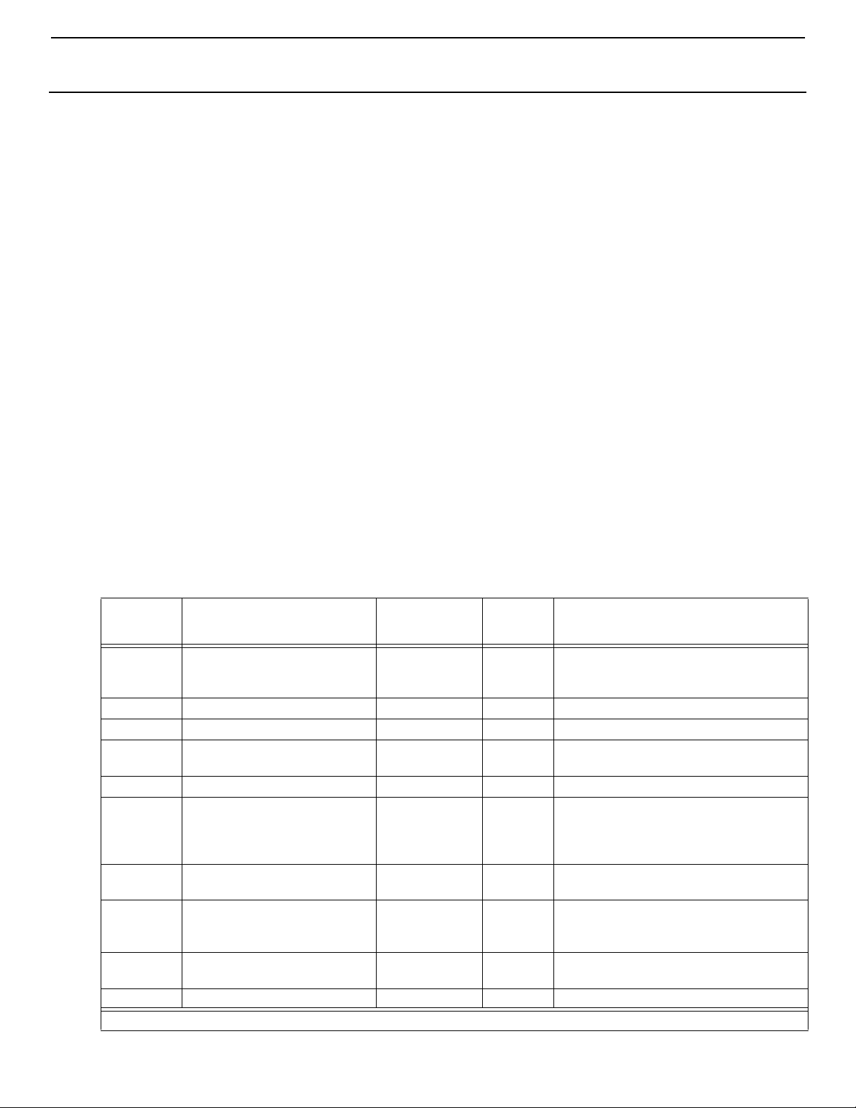
Table 2: Programmable Parameters - Ranges and Factory Defaults
Parameter
Number
Description
Radome ECU
Factory
Default
Custom
Default
Parameter Range
P-1 Operating Mode 1 0 = Auto
1 = Cool Only
2 = Heat Only
P-2 High Fan-Speed Limit 95 65 - 95
P-3 Low Fan-Speed Limit 64 30 - 64
P-4 Compressor Staging Time
135 5 - 135 seconds
Delay
P-5 Temperature-Sensor Calibration Ambient temp Ambient plus or minus 10° F
P-6 Failsafe Level 2 0 = Minimal Protection
1 = Continuous No Display
2 = Continuous With Display
3 = Four Failures Reset Required
P-7 Low AC Voltage Shutdown
(Volts)
115V: OFF
220/230V: OFF
115V: 75 - 105
220/230V: 175 - 205
P-8 De-Icing Cycle OFF OFF
1 = On with 5°F Display Sensor Differential
2 = On with 7°F Display Sensor Differential
P-9 Pump Sentry OFF OFF
On = Select 100°F to 150°F
P-10 Display Brightness Control 9 4 (Dimmest) - 13 (Brightest)
L-2283 ENGLISH 9
Page 12
OPERATION Radome Environmental Control Unit
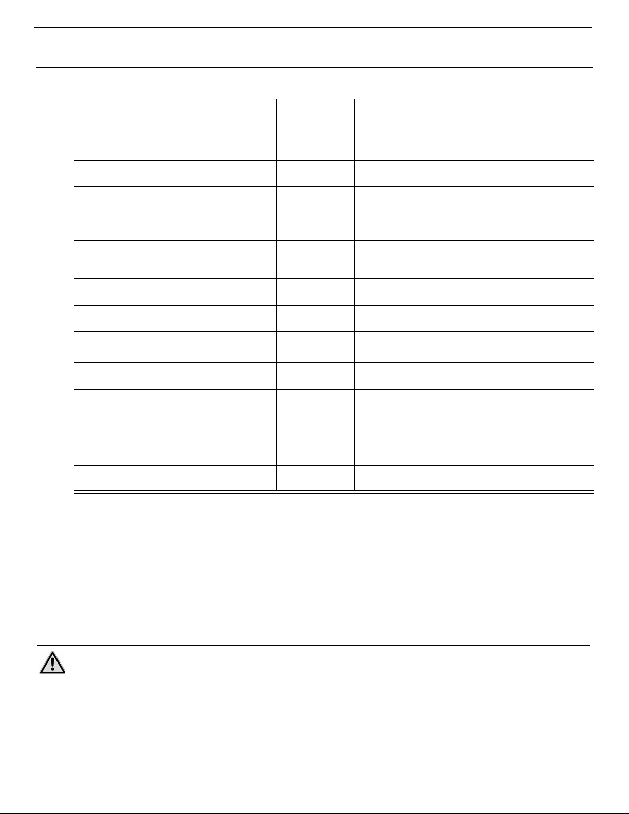
Table 2: Programmable Parameters - Ranges and Factory Defaults (continued)
Parameter
Number
Description
P-11 Display Temperatures in
Fahrenheit or Celsius
P-12 Cycle Pump With Compressor
or Continuous Pump
P-13 Reverse Fan Speeds During
Heat Mode
P-14 Continuous Fan or Cycle Fan
With Compressor
P-15 Reverse-Cycle Heating or
Electric-Heat-Only Option
Radome ECU
Factory
Default
Custom
Default
Parameter Range
F F = Fahrenheit Displayed
C = Celsius Displayed
OFF OFF = Cycle With Compressor
On = Continuous Pump
rEF nor = Normal Fan Operation
rEF = Reversed Fan in Heat Mode
con CYC = Cycle Fan With Compressor
con = Continuous Fan Operation
nor nor = Reverse-Cycle Heating
ELE = Electric Heater Installed
Installed
P-16 Fan-Motor Type: Split Capacitor
or Shaded Pole
P-17 Reset Memorized Programming
Defaults
SC SC = Split Capacitor Fan Motor
SP = Shaded Pole Fan Motor
nor rST = Reset Defaults
nor = Normal
P-18 Reserved for future use
P-19 Reserved for future use
P-20 Air Filter Cleaning/Replacement
Timer Setting (x10 hours)
P-21 Current Filter Time (x10 hours)
and Reset
0 0 = Timer Disabled
10 - 250 (100 - 2500 hours)
0 Displays the elapsed time (in hours x10)
since the timer was started or reset. Press
Down button to reset value to 0, restart the
timer, and clear the display’s “FIL”
reminder.
P-22 Voltage Calibration AC Voltage
P-23 Auto Mode Heat Differential OFF OFF
On = Select 4°F to 40°F
OPERATION
1. Turn on the A/C circuit breaker.
2. Turn the Radome ECU system on by pressing the Power button.
3. Use the Up or Down buttons to set the temperature (set point) to 85
4. Verify that there is a steady airflow out of the supply-air grille.
5. If the unit does not appear to be operating properly, refer to the “TROUBLESHOOTING GUIDELINES”, below.
NOTE
Do not turn the unit off and immediately turn it back on. Allow at least 30 seconds for refrigerant pressure to equalize.
10 L-2283 ENGLISH
°F.
Page 13
Radome Environmental Control Un it TROUBLESHOOTING GUIDELINES
TROUBLESHOOTING GUIDELINES
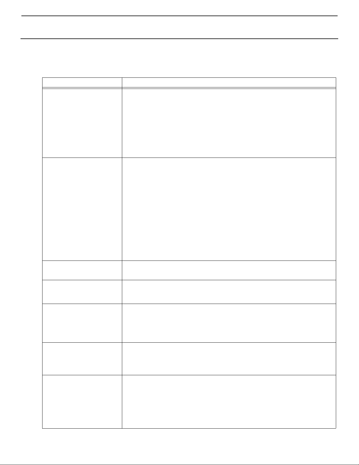
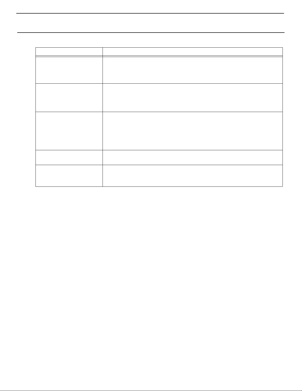
Table 3: General Troubleshooting
PROBLEM POSSIBLE REASON/SOLUTION
System will not start. 1. Air conditioner circuit breaker is off. Turn circuit breaker on at ship’s panel.
2. Digital control is not turned on. Press the Power button.
3. Wrong wiring at terminal strip. Check wiring diagram; correct if necessary.
4. Input-line voltage is ins ufficient. Check power source (shore/generator) for proper
voltage. Check wiring and terminals for proper sizes and connections. Verify with a
volt-meter that the power at the unit is the same as the power source.
5. Push-on connectors or butt splices became disconnected during installation.
Disconnect power supply then open electric box, check wiring diagram, correct if
necessary.
No cooling. 1. Temperature set point is satisfied. Lower or raise set point.
2. Passport I/O Compact programmed for heat. Reprogram parameter P-1 for Cool
Mode.
3. Obstructed condenser air flow. Check for obstructions at condenser air inlet.
4. Loss of refrigerant gas. Check air conditioning unit for refrigerant oil leakage, call
service technician.
5. Coil is iced. See below.
6. Fan is not running. See below.
7. “HPF” is displayed on panel. See below.
8. “LPF” is displayed on panel. See below.
9. Compressor’s thermal overload is open due to either of the above reasons.
Compressor needs to cool down. Turn system off for a while (it may take up to three
hours to reset thermal overload).
System runs continuously. 1. Set point temperature is set too low for cooling. Raise set point to 85°F.
2. Porthole or hatches open. Close all port holes and hatches.
Passport I/O Compact
display panel not lit.
Fan is not running but the
compressor is.
Low airflow. 1. Airflow is blocked. Remove any obstructions in return-air stream. Clean return-air
Coil is iced. 1. Thermostat set point is too low. Raise set point to 85°F.
8-pin display cable plugs are not making contact (unplugged, dirty, bent, or broken
pins). With MAIN POWER OFF at the circuit breaker, remove connector and inspect. If
damaged, replace connector or entire display cable.
1. Troubleshoot fan capacitor and wiring. Send for repair or call local service
technician.
2. Check the condenser fan transformer fuse in the electric box. If blown, replace
with an idential fuse (15A MDL) and try to run unit. If fuse blows again, call service
technician.
filter and grille. Check for crushed or restricted ducting; ducting must be as straight,
smooth and taut as possible.
2. Coil is iced. See below.
2. Improper airflow. Remove any obstructions in return air stream. Clean return air filter
and grille. Check for crushed or restricted ducting, must be as straight, smooth and
taut as possible. See the Digital Controls Troubleshooting section below for
reprogramming options.
3. Supply air is short-cycling. Redirect supply air so that is not blowing into the return
air stream. Seal any air leaks on duct.
L-2283 ENGLISH 11
Page 14
MAINTENANCE Radome Environmental Control Unit
Table 3: General Troubleshooting (continued)
PROBLEM POSSIBLE REASON/SOLUTION
"HPF" is displayed on digital
control.
(High Refrigerant Pressure)
"LPF" is displayed on digital
control.
(Low Refrigerant Pressure)
"ASF" is displayed.
(Air Sensor Failure)
"FIL" is flashing
(Filter Reminder)
"LAC" is displayed.
(Low AC Voltage)
1. High-pressure switch open due to improper airflow. Remove obstructions in air
intake or exhaust. Confirm air is not short cycling from intake to exhaust. Ensure
intake air is ambient temperature.
2. Condenser fan not running. Troubleshoot if necessary.
1. Thermostat set point is too low. Raise to 85°F.
2. Evaporator blower is not running. Check to confirm. Troubleshoot if necessary.
3. Low pressure switch is open due to loss of refrigerant. Check air conditioning unit
for refrigerant oil leakage, call service technician.
1. Indicates failed face plate air sensor, alternate air sensor or display cable.
Unplug alternate air sensor if installed or plug in alternate air sensor if not installed.
Try another display cable.
2. Damaged jack/socket in display head or on ci rcuit board. Visually check to see
that pins inside socket are not bent or corroded. Repair or replace display or circuit
board if needed.
Filter needs to be cleaned or replaced. Clean or replace filter, and reset P-21 to "00”.
1. Supply voltage is too low. Verify power to unit with multimeter.
2. Voltage is improperly calibrated. Verify that P-22 matches voltage reading to unit
with a multimeter. Adjust P-22 if necessary.
MAINTENANCE
CONDENSER COIL
Check the condenser coil for build-up of dust or soot. Wipe with a dry cloth. Clean as needed and check annually.
RETURN-AIR FILTERS
Check the return-air filter about once a month and clean as necessary. To clean the filter, remove it from the unit, rinse with
water, air dry, and reinstall.
DIAGRAMS
WIRING & PRODUCT DIAGRAMS
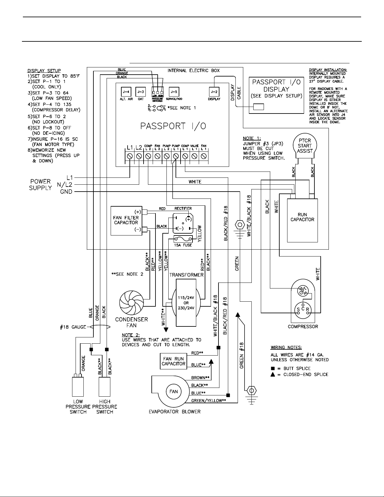
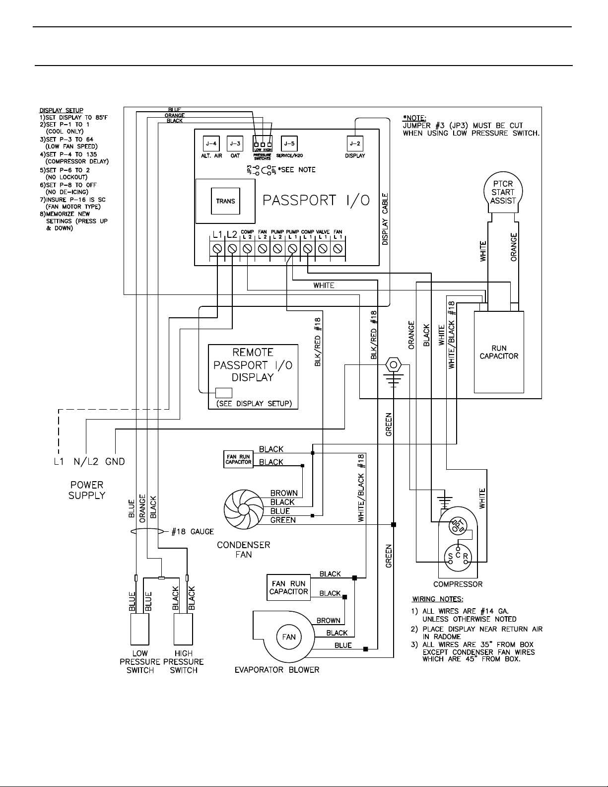
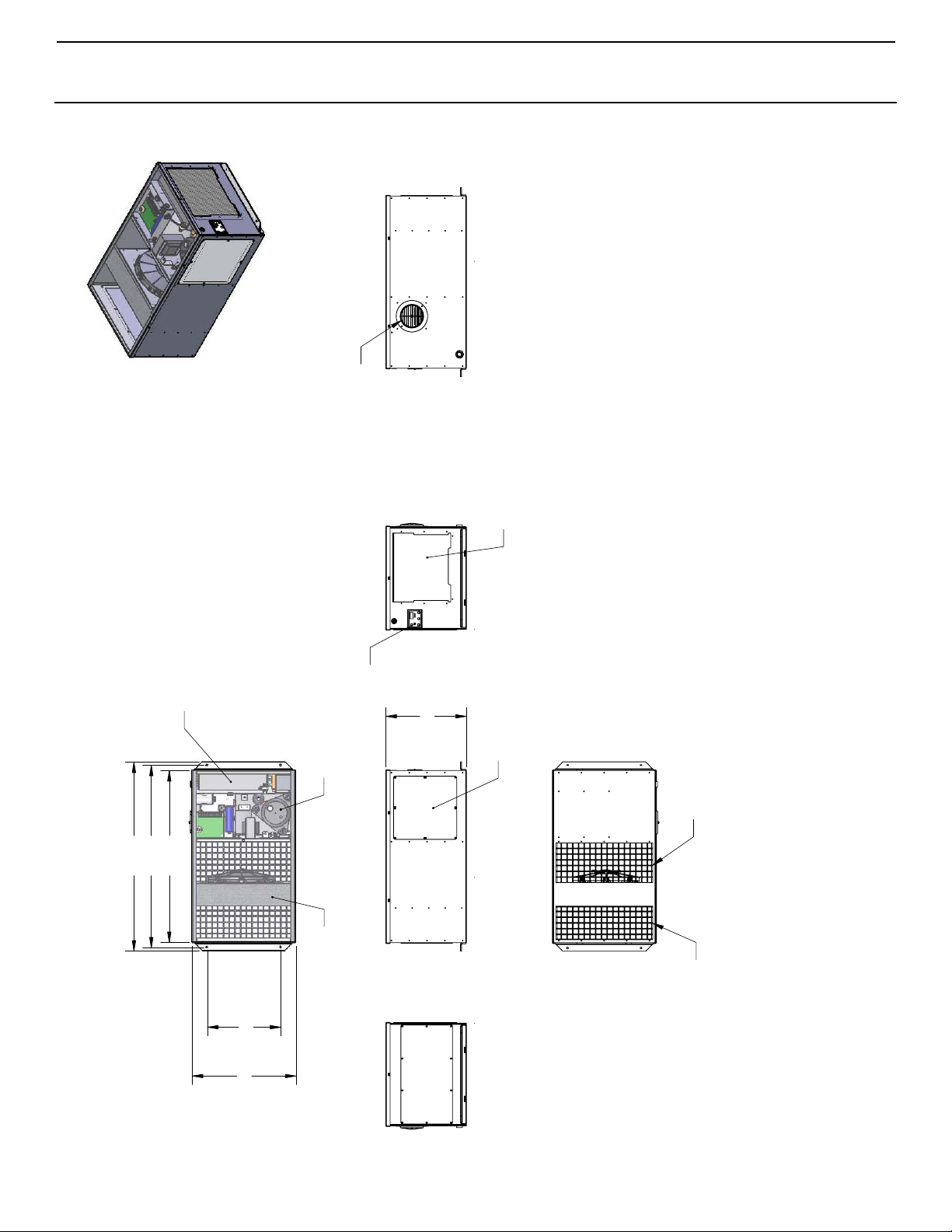
Wiring and product diagrams are provided on the following pages for each Radome ECU model.
12 L-2283 ENGLISH
Page 15
Radome Environmental Control Un it DIAGRAMS
Figure 2: HSA 16K-C/CZ/CZ50 Self-Contained Wiring Diagram
(for units shipped after August 1, 2009)
L-2283 ENGLISH 13
Page 16
DIAGRAMS Radome Environmental Control Unit
Figure 3: HSA 16K-C/CZ/CZ50 Self-Contained Wiring Diagram
(for units shipped prior to August 1, 2009)
14 L-2283 ENGLISH
Page 17
Radome Environmental Control Un it DIAGRAMS
14.06
ACCESS PANEL
RETURN
AIR
INTAKE
DISPLAY
PANEL
33.00
31.87
30.00
18.13
12.80
CONDENSER COMPRESSOR
EVAPORATOR
CONDENSER
AIR
DISCHARGE
CONDENSER
AIR
INTAKE
SUPPLY
AIR
DISCHARGE
THE INFORMATION CONTAINED IN THIS
DRAWING IS THE SOLE PROPERTY OF
DOMETIC CORPORATION. ANY
REPRODUCTION IN PART OR AS A WHOLE
WITHOUT THE WRITTEN PERMISSION OF
DOMETIC CORPORATION IS
PROHIBITED
PROPRIETARY AND CONFIDENTIAL
DIMENSIONS ARE IN INCHES
TOLERANCES:
FRACTIONAL
1/32
ANGULAR:
BEND
1
TWO PLACE DECIMAL
THREE PLACE DECIMAL
N/A
DRAWN
CHECKED
DATE
NAME
DESCRIPTION:
SIZE
B
DWG NO.
RE
WEIGHT:
SCALE: 1:8
UNLESS OTHERWISE SPECIFIED:
0
DRR
RAP
6/19/09
6/19/09
HSA16K(C/CZ/CZ50)
2nd GENERATION RADOME
W/PASSPORT I/O CONTROL
SHEET 1 O
E1020013
DO NOT SCALE DRAWING
DOMETIC CORPORATIO
.03
.010
FINISH
MATERIAL
NOTES:
Figure 4: HSA 16K-C/CZ/CZ50 Self-Contained Product Diagram
L-2283 ENGLISH 15
Page 18
DIAGRAMS Radome Environmental Control Unit
TEMPLATE FOR INTERIOR UNIT
Figure 5: Mounting Template For Interior Self-Contained System
16 L-2283 ENGLISH
Page 19
Radome Environmental Control Un it DIAGRAMS
MOUNTING DIAGRAMS
Figure 6: Mounting Diagram For Self-Contained System
L-2283 ENGLISH 17
Page 20
DIAGRAMS Radome Environmental Control Unit
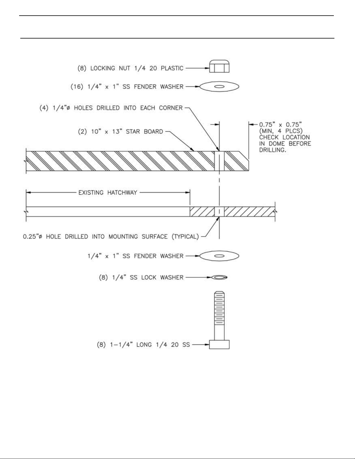
Figure 7: Mounting Diagram For System With Existing Hatchway Covers
18 L-2283 ENGLISH
Page 21

NOTES
Page 22

NOTES
Page 23

NOTES
Page 24

DOMETIC MARINE DIVISION
2000 N. Andrews Ave.
Pompano Beach, FL 33069 USA
Tel +1 954-973-2477
Fax +1 954-979-4414
Email [email protected]
24/7 TECH SUPPORT FOR UNITED STATES AND CANADA
8:00 AM to 5:00 PM Eastern Time: +1 800-542-2477
After hours and weekends: +1 888-440-4494
INTERNATIONAL SALES AND SERVICE
Europe and the Middle East: +44 (0) 870-330-6101
For all other areas visit our website to find your nearest distributor.
dometic.com
L-2283 | 06/01/2017
 Loading...