

Dometic PerfectView CAM301 Installation And Operating Manual
EN
DEDEFRESPTITNLDASVNOFIRUPLSKCSHU
DRIVING SUPPORT
PERFECTVIEW
CAM301
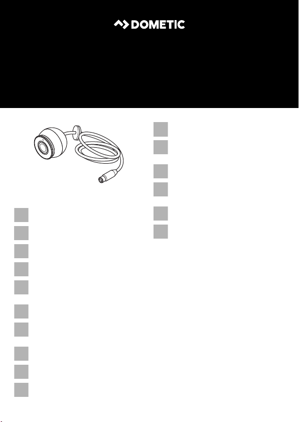
Additional camera
Installation and Operating Manual . . . . . . 6
Kugelka mera
Montage- und Bedienungsanleitung . . . 17
Caméra supplémentaire
Instructions de montage et de service . . 28
Cámara adicional
Instrucciones de montaje y de uso . . . . . 39
Câmara adicional
Instruções de montagem e manual de
instruções . . . . . . . . . . . . . . . . . . . . . . . . . 50
Telecamera aggiuntiva
Istruzioni di montaggio e d’uso . . . . . . . . 61
Extra camera
Montagehandleiding en
gebruiksaanwijzing. . . . . . . . . . . . . . . . . . 72
Ekstra kamera
Monterings- og betjeningsvejledning. . . 83
Extra kamera
Monterings- och bruksanvisning . . . . . . . 94
Tilleggskamera
Monterings- og bruksanvisning . . . . . . .104
Lisäkamera
Asennus- ja käyttöohje. . . . . . . . . . . . . . .114
Вспомогательная камера
Инструкция по монтажу
и эксплуатации. . . . . . . . . . . . . . . . . . . . 124
Dodatkowa kamera
Instrukcja montażu i obsługi . . . . . . . . . 135
Prídavná kamera
Návod na montáž a uvedenie
do prevádzky . . . . . . . . . . . . . . . . . . . . . 147
Přídavná kamera
Návod k montáži a obsluze . . . . . . . . . . 157
Kiegészítő kamera
Szerelési és használati útmutató . . . . . . 168
PerfectView
1
2
12
3
3
2
PerfectView
3
4
5
2
1
4
AB
1.
2.
1.
5
3
6
M5 x 25 mm
A
B
7
8
A
B
9
PerfectView
4
PerfectView
A
B
ge
ge
gn
gn
0
DE EN FR ES IT NL DA SV
ge Gelb Yellow Jaune Amarillo Giallo Geel Gul Gul
gn Grün Green Vert Verde Verde Groen Grøn Grön
NO FI PT RU PL CS SK HU
ge Gul Kel tainen Amarelo Желтый Żółty Žlutá Žltá Sárga
gn Grønn Vihreä Ver de Зеленый Zielony Zelen á Zelená Zöld
5

Description of symbols PerfectView
EN
Please read this instruction manual carefully before installati on and first use, and store
it in a safe place. If you pass on the product to another person, hand over this instruction manual along with it.
Table of contents
1 Description of symbols . . . . . . . . . . . . . . . . . . . . . . . . . . . . . . . . . . . . . . . . . . . . . . . . . . . . . . . 6
2 Safety and installation instructions . . . . . . . . . . . . . . . . . . . . . . . . . . . . . . . . . . . . . . . . . . . . . .7
3 Scope of delivery . . . . . . . . . . . . . . . . . . . . . . . . . . . . . . . . . . . . . . . . . . . . . . . . . . . . . . . . . . . 9
4 Accessories . . . . . . . . . . . . . . . . . . . . . . . . . . . . . . . . . . . . . . . . . . . . . . . . . . . . . . . . . . . . . . . . 9
5 Intended use . . . . . . . . . . . . . . . . . . . . . . . . . . . . . . . . . . . . . . . . . . . . . . . . . . . . . . . . . . . . . . . 9
6 Technical description . . . . . . . . . . . . . . . . . . . . . . . . . . . . . . . . . . . . . . . . . . . . . . . . . . . . . . . 10
7 General instructions for electrical connection . . . . . . . . . . . . . . . . . . . . . . . . . . . . . . . . . . . . 10
8 Fitting the camera . . . . . . . . . . . . . . . . . . . . . . . . . . . . . . . . . . . . . . . . . . . . . . . . . . . . . . . . . . 11
9 Connecting the camera . . . . . . . . . . . . . . . . . . . . . . . . . . . . . . . . . . . . . . . . . . . . . . . . . . . . . 14
10 Checking the function and setting the camera . . . . . . . . . . . . . . . . . . . . . . . . . . . . . . . . . . . 14
11 Cleaning and caring for the camera . . . . . . . . . . . . . . . . . . . . . . . . . . . . . . . . . . . . . . . . . . . . 15
12 Warranty . . . . . . . . . . . . . . . . . . . . . . . . . . . . . . . . . . . . . . . . . . . . . . . . . . . . . . . . . . . . . . . . . 15
13 Disposal. . . . . . . . . . . . . . . . . . . . . . . . . . . . . . . . . . . . . . . . . . . . . . . . . . . . . . . . . . . . . . . . . . 15
14 Technical data . . . . . . . . . . . . . . . . . . . . . . . . . . . . . . . . . . . . . . . . . . . . . . . . . . . . . . . . . . . . . 16
1 Description of symbols
WARN ING !
!
!
Safety instruction: Failure to observe this instruction can cause fatal or serious injury.
CAUTION!
Safety instruction: Failure to observe this instruction can lead to injury.
A
I
6
NOTICE!
Failure to observe this instruction can cause material damage and impair the function
of the product.
NOTE
Supplementary information for operating the product.

PerfectView Safety and installation instructions
EN
2 Safety and installation instructions
The manufacturer accepts no liability for damage in the following cases:
•
Damage to the product resulting from mechanical influences and incorrect connection voltage
•
Alterations to the product without express permission from the manufacturer
•
Use for purposes other than those described in the operating manual
Please observe the prescribed safety instructions and stipulations from the vehicle
manufacturer and service workshops.
WARN ING !
Inadequate supply cable connections could result in short circuits, causing:
!
•
Cable fires
•
The airbag being triggered
•
Damage to electronic control equipment
•
Electrical malfunctions (indicators, brake light, horn, ignition, lights)
NOTICE!
To prevent the risk of short circuits, always disconnect the negative terminal of the
A
vehicle's electrical system before working on it.
If the vehicle has an additional battery, its negative terminal should also be disconnected.
Therefore, please observe the following instructions:
•
When working on the following cables, use only insulated cable lugs, plugs and tab sleeves.
– 30 (direct supply from positive battery terminal)
–15 (connected positive terminal, behind the battery)
– 31 (return cable from the battery, earth)
– 58 (reversing light)
Do not use porcelain wire connectors.
•
Use a crimping tool to connect the cables. For permanent connections, you can solder the
cable ends together and then insulate them.
•
Screw the cable when connecting cable 31 (earth)
– Screw on the cable using a cable terminal and serrated washer to one of the v ehicle's earth
bolts or
– screw the cable to the bodywork using a cable terminal and a self-tapping screw.
Make sure there is a good earth connection.
7

Safety and installation instructions PerfectView
EN
If you disconnect the negative terminal of the battery, all data stored in the volatile memories will
be lost.
•
The following data must be reset, depending on the vehicle equipment options:
–Radio code
– Vehicle clock
–Timer
– On-board computer
– Seat position
You can find instructions for making these settings in the operating manual.
Note the following instructions during installation:
•
Secure the parts of the camera installed in the vehicle in such a way that they cannot become
loose under any circumstances (sudden braking, accidents) or cause injuries to the occu-
pants of the vehicle.
•
Secure any parts of the system concealed by the bodywork in such a manner that they cannot
be come loose or damage other parts or cables, or impair vehicle functions (steering, pedals,
etc.).
•
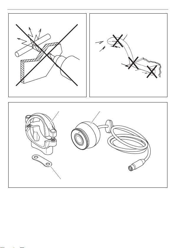
To prevent damage when drilling, make sure there is sufficient space on the other side for the
drill head to come out (fig. 1, page 2).
•
Deburr all drill holes and treat them with a rust-protection agent.
•
Always follow the safety instructions of the vehicle manufacturer.
Some work (e.g. on retention systems such as the AIRBAG etc.) may only be performed by
qualified specialists.
Observe the following instructions when working with electrical parts:
•
When testing the voltage in electrical cables, only use a diode test lamp or a voltmeter.
Test lamps with a bulb consume too much voltage, which can damage the vehicle's electronic
system.
•
When making electrical connections, ensure that:
– they are not kinked or twisted
– they do not rub on edges
– they are not laid in sharp-edged ducts without protection (fig. 2, page 2).
•
Insulate all connections.
•
Secure the cables against mechanical stress with cable binders or insulating tape, for example,
to existing lines.
8

PerfectView Scope of delivery
EN
The camera is watertight. However, the seals on the camera cannot withstand a high-pressure
cleaner. Therefore, you should observe the following instructions when handling the camera:
•
Do not open the camera, as this impairs the tightness and the function of the camera.
•
Do not pull at the cables, as this impairs the leak-tightness and the function of the camera.
•
The camera is not suitable for submerged operation.
3Scope of delivery
No. in
fig. 3,
page 2
Quantity Description Ref. no.
11Camera
2 1 Top and bottom camera holder
31Insulation pad
–1Fastening material
CAM301 color camera 9600005898
4 Accessories
Description Ref. no.
Extension cable, 5 m 9600000206
Extension cable, 10 m 9600000207
Extension cable, 20 m 9600000208
Spiral cable for trailer operation 9600000235
5Intended use
The CAM 301 color camera is primarily intended for use in vehicles. It can be used in reversing
video systems that serve to monito r the area directly next to or behind the vehicle from the driver's
seat, for example, during maneuvering or parking.
Reversing video systems are designed merely as an additional aid for reversing, however this
does not relieve you of the duty to take proper care when reversing.
9

Technical description PerfectView
EN
6 Technical description
6.1 Function description
The camera is located in an aluminium case and transfers the image via a cable to a monitor. The
built-in infrared LEDs improve night vision.
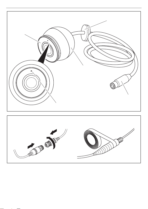
The camera consists of the following elements:
No. in
fig. 4, page 3
1 Infrared LEDs
2Sleeve
36-pin connection cable
4Plug
5LDR sensor
Description
7 General instructions for electrical connection
7.1 Lay in g c ab le s
NOTICE!
A
I
The cables may not be exposed for long periods to solvents such as benzene, since
they can damage the cable.
NOTE
•
As far as possible, use original ducts for laying the cables, or other suitable options
such as paneling edges, ventilation grills or dummy plugs. If no openings are available, you must drill holes for the cables. Check beforehand that there is sufficient
space on the other side for the drill head to emerge.
•
Cables and connections that are not properly installed will cause malfunctions or
damage to components. Correct installation of cables and connections ensures
lasting and trouble-free operation of the retrofitted components.
10

PerfectView Fitting the camera
EN
Therefore, please observe the following instructions:
•
Wherever possible, lay cables inside the vehicle, as they are better protected there than outside.
If you do need to lay a cable outside the vehicle, ensure that it is well fastened (use additional
cable ties, insulating tape etc.).
•
To prevent damage to the cables when laying them, ensure that they are far enough away from
hot or moving vehicle components (exhaust pipes, drive shafts, light systems, fans, heaters,
etc.). Use corrugated piping or other protective materials to protect against mechanical wear.
•
When laying the cables, make sure:
– they are not kinked or twisted
– they do not rub on edges
– they are not laid in sharp-edged ducts without protection (fig. 2, page 2).
•
Attach the cables securely in the vehicles to prevent tripping hazards. This can be performed by
using cable binders, insulating tape or gluing in place with adhesives.
•
Protect every through-hole made in the bodywork against water penetration, e.g. by using a
cable with a sealant and by spraying the cable and the cable sleeve with sealant.
NOTE
I
Only start sealing through-holes when you have completed all installation work on the
camera and have laid the required cable lengths.
8 Fitting the camera
NOTICE!
A
I
Select a location for the camera and attach it firmly enough so that it cannot under any
circumstances fall off and injure bystanders (e.g. by being knocked off by branches
brushing over the roof of the vehicle).
NOTE
If installing the camera alters the vehicle height or the length specified in the vehicle
documents, your vehicle must be inspected by the appropriate authorities. This
authority must note any such changes your vehicle documents.
Note the following instructions during installation:
•
To provide a suitable viewing angle, the camera must be attached at a height of at least 2 m.
Ensure that you have a firm place from which to work when mounting the camera.
•
Make sure that the installation location of the camera is sufficiently firm (e.g. to prevent the
camera from being knocked down by branches that may brush the roof of the vehicle).
•
Always use the supplied insulation pad (fig. 3 3, page 2). This prevents residual currents due
to bad ground connections in the vehicle. Residual current can cause lines of interference in the
picture or buzzing in the loudspeakers or even damage components.
11

Fitting the camera PerfectView
EN
•
Observe the fastening instructions:
– There must be sufficient space behind the chosen installation location to be able to carry
out the mounting procedure.
– Suitable measures must be taken to prevent water penetrating through any holes made
(e.g. by using screws and sealant and/or spraying the outer attachment parts with sealant).
– The location on the body where you wish to attach the camera must be rigid enough to
allow the camera to be tightly fastened.
•
Check beforehand that there is suffici ent space on the other side for the drill head to come out
(fig. 1, page 2).
•
If you are not sure about the location you have chosen, ask your vehicle manufacturer or dealer.
NOTE
I
To perform the installation, proceed as follows:
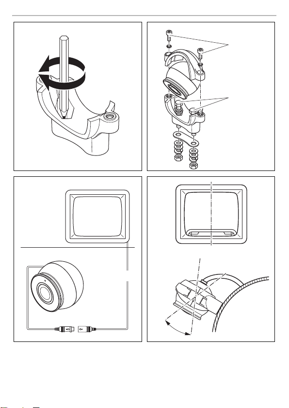
➤ Hold the lower camera holder on the selected installation location and mark two drilling points
➤ Using a hammer and center punch, gently pre-punch the previously marked points to prevent
If you want to screw on the bottom camera holder with self-tapping screws
A
➤ Drill the holes, with a Ø of 2 mm, at each of the markings.
➤ Deburr all drill holes and apply rust-protection.
➤ Place the insulating plate (fig. 3 3, page 2) on the installation location of the lower camera
➤ Screw on the camera holder using the self-tapping screws.
We recommend greasing the threads of the bolts to prevent corrosion.
(fig. 6, page 4).
the drill head from slipping off.
NOTICE!
Self-tapping screws may only be fastened to steel metal with a minimum thickness of
1.5 mm.
holder.
The insulating plate also serves as a seal and paint protection.
12

PerfectView Fitting the camera
EN
If you want to attach the lower camera holder with screws when installing
NOTICE!
A
➤ Drill the holes, with a Ø of 5.5 mm, at each of the markings.
➤ Deburr all drill holes and apply rust-protection.
➤ Place the insulating plate (fig. 3 3, page 2) on the installation location of the lower camera
➤ Screw on the lower camera bracket with the M5 x 25 mm threaded screws (fig. 7 A, page 4).
Fastening the camera
➤ Push the camera into the bottom camera holder.
I
➤ Fasten the camera loosely with the upper camera holder and the two screws (fig. 7 B,
I
Creating a through-hole for the camera connection cable
I
Ensure that nuts cannot be pulled through the body shell when they are tightened.
Use larger washers or metal plates if necess ary.
holder.
The insulating plate also serves as a seal and paint protection.
Depending on the thickness of the construction, you may require longer threaded screws.
NOTE
Keep in mind that the LDR sensor (fig. 4 4, page 3) should be faced downwards so
that the image is displayed correctly on the monitor.
page 4).
NOTE
Do not tighten the two screws until you have aligned the camera (see chapter “Checking the function and setting the camera” on page 14).
If necessary, you may have to first install and electrically connect a monitor (see principle circuit diagram fig. 8, page 4).
NOTE
If possible, use available openings, such as ventilation grilles, to feed the connection
cables through. If there are no existing ducts, you must drill a hole of Ø 16 mm. Check
beforehand that there is sufficient space on the other side for the drill head to come
out.
➤ Drill a hole of Ø 16 mm near the camera.
➤ Deburr all drill holes that have been made in the sheet metal and apply rust-protection.
➤ Seal the feed through with the cable sleeve (fig. 4 3, page 3).
13

Connecting the camera PerfectView
EN
9 Connecting the camera
NOTE
I
➤ Guide the camera cable into the vehicle interior.
➤ Insert the camera cable plug into the socket of the monitor cable (fig. 8, page 4).
I
Lay the camera cable so that, should you need to remove the camera, you can access
the plug connection between the camera and the extension cable easily. This simplifies dismantling considerably.
NOTE
•
To minimize corrosion in the plug, apply a small amount of grease, such as pin
grease, in one of the plugs.
•
Extension cables are available if needed (see chapter “Accessories” on page 9).
•
The cable plug connections are waterproof (IP67). As an option you can add a sealing tape to the connections (fig. 5 B, page 3).
10 Checking the function and setting the camera
➤ Check the function of the camera after you have connected it to a monitor.
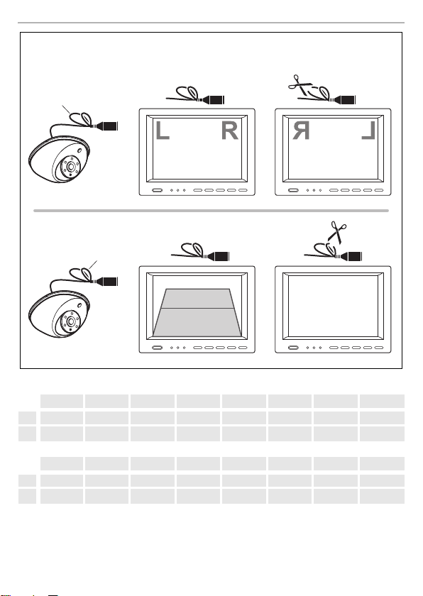
➤ If necessary adjust the camera using the monitor image:
The monitor image should show the rear or the bumper of the vehicle at the bottom edge of
the screen. The middle of the bumper should be in the middle of the screen (fig. 9, page 4).
➤ Tighten the two fastening screws of the top camera holder.
Settings for contrast and brightness can be made on the monitor.
Activating mirror function
See fig. 0 A, page 5.
Deactivating distance markers
See fig. 0 B, page 5.
14

PerfectView Cleaning and caring for the camera
EN
11 Cleaning and caring for the camera
NOTICE!
A
➤ Occasionally clean the device with a soft, damp cloth.
Do not use any sharp or hard objects for cleaning since they may damage the device.
12 Warranty
The statutory warranty period applies. If the product is defective, please contact the
manu factu rer's b ranch i n your c ountry (see th e back o f the in struct ion ma nual fo r the ad dresse s) or
your retailer.
For repair and warranty processing, please include the following documents when you send in the
device:
•
A copy of the receipt with purchasing date
•
A reason for the claim or description of the fault
13 Disposal
➤ Place the packaging material in the appropriate recycling waste bins wherever possible.
If you wish to finally dispose of the product, ask your local recycling centre or specialist
dealer for details about how to do this in accordance with the applicable disposal
M
regulations.
15

Technical data PerfectView
EN
13
14 Technical data
PerfectView CAM301
Ref. no.: 9600005898
Video system: PAL
Image sensor: 1/3" color CMOS sensor
Pixels: Approx. 320000 pixels
Sensitivity
without LED
with LED:
Video output: 1 Vp-p 75 Ω
Operating temperature: –20 °C to +70 °C
Operating voltage: 10 Vg
Consumption: Max. 150 mA
Dimensions W x H x D (with bracket): 84 x 58 x 44 mm
Weight: approx. 80 g
Certifications
This device has E13 approval.
0.5 lux
0 lux
to 16 Vg
16

PerfectView Erklärung der Symbole
DE
Bitte lesen Sie diese Anleitung vor Einbau und Inbetriebnahme sorgfältig durch und
bewahren Sie sie auf. Geben Sie sie im Falle einer Weitergabe des Produktes an den
Nutzer weiter.
Inhaltsverzeichnis
1 Erklärung der Symbole . . . . . . . . . . . . . . . . . . . . . . . . . . . . . . . . . . . . . . . . . . . . . . . . . . . . . . 17
2 Sicherheits- und Einbauhinweise . . . . . . . . . . . . . . . . . . . . . . . . . . . . . . . . . . . . . . . . . . . . . . 18
3 Lieferumfang . . . . . . . . . . . . . . . . . . . . . . . . . . . . . . . . . . . . . . . . . . . . . . . . . . . . . . . . . . . . . .20
4 Zubehör . . . . . . . . . . . . . . . . . . . . . . . . . . . . . . . . . . . . . . . . . . . . . . . . . . . . . . . . . . . . . . . . .20
5 Bestimmungsgemäßer Gebrauch . . . . . . . . . . . . . . . . . . . . . . . . . . . . . . . . . . . . . . . . . . . . .20
6 Technische Beschreibung . . . . . . . . . . . . . . . . . . . . . . . . . . . . . . . . . . . . . . . . . . . . . . . . . . . 21
7 Allgemeine Hinweise zum elektrischen Anschluss . . . . . . . . . . . . . . . . . . . . . . . . . . . . . . . . 21
8 Kamera montieren . . . . . . . . . . . . . . . . . . . . . . . . . . . . . . . . . . . . . . . . . . . . . . . . . . . . . . . . .22
9 Kamera anschließen . . . . . . . . . . . . . . . . . . . . . . . . . . . . . . . . . . . . . . . . . . . . . . . . . . . . . . . .25
10 Funktion prüfen und Kamera einstellen . . . . . . . . . . . . . . . . . . . . . . . . . . . . . . . . . . . . . . . . . 25
11 Kamera pflegen und reinigen . . . . . . . . . . . . . . . . . . . . . . . . . . . . . . . . . . . . . . . . . . . . . . . . .26
12 Gewährleistung . . . . . . . . . . . . . . . . . . . . . . . . . . . . . . . . . . . . . . . . . . . . . . . . . . . . . . . . . . .26
13 Entsorgung . . . . . . . . . . . . . . . . . . . . . . . . . . . . . . . . . . . . . . . . . . . . . . . . . . . . . . . . . . . . . . .26
14 Technische Daten . . . . . . . . . . . . . . . . . . . . . . . . . . . . . . . . . . . . . . . . . . . . . . . . . . . . . . . . . . 27
1 Erklärung der Symbole
WARN UNG !
!
!
Sicherheitshinweis: Nichtbeachtung kann zu Tod oder schwerer Verletzung führen.
VORSIC HT!
Sicherheitshinweis: Nichtbeachtung kann zu Verletzungen führen.
A
I
ACHTUNG!
Nichtbeachtung kann zu Materialschäden führen und die Funktion des Produktes
beeinträchtigen.
HINWEIS
Ergänzende Informationen zur Bedienung des Produktes.
17

Sicherheits- und Einbauhinweise PerfectView
DE
2 Sicherheits- und Einbauhinweise
Der Hersteller übernimmt in folgenden Fällen keine Haftung für Schäden:
•
Beschädigungen am Produkt durch mechanische Einflüsse und falsche Anschlussspannung
•
Veränderungen am Produkt ohne ausdrückliche Genehmigung vom Hersteller
•
Verwendung für andere als die in der Anleitung beschriebenen Zwecke
Beachten Sie die vom Fahrzeughersteller und vom Kfz-Handwerk vorgeschriebenen
Sicherheitshinweise und Auflagen!
WARN UNG !
Unzureichende Leitungsverbindungen können zur Folge haben, dass durch Kurzschluss
!
•
Kabelbrände entstehen,
•
der Airbag ausgelöst wird,
•
elektronische Steuerungseinrichtungen beschädigt werden,
•
elektrische Funktionen ausfallen (Blinker, Bremslicht, Hupe, Zündung, Licht).
ACHTUNG!
Klemmen Sie wegen der Kurzschlussgefahr vor Arbeiten an der Fahr zeugelektrik immer
A
den Minuspol ab.
Bei Fahrzeugen mit Zusatzbatt erie müssen Sie an dieser ebenfalls den Minuspol abklemmen.
Beachten Sie deshalb folgende Hinweise:
•
Verwenden Sie bei Arbeiten an den folgenden Leitungen nur isolierte Kabelschuhe, Stecker
und Flachsteckhülsen.
– 30 (Eingang von Batterie Plus direkt),
– 15 (Geschaltetes Plus, hinter Batterie),
– 31 (Rückleitung ab Batterie, Masse),
– 58 (Rückfahrscheinwerfer).
Verwend en Si e keine Lüsterklemmen.
•
Verwenden Sie eine Krimpzange zum Verbinden der Kabel. Für Verbindungen, die nicht
wieder gelöst werden sollen, können Sie die Kabelenden miteinander verlöten und
anschließend isolieren.
•
Schrauben Sie das Kabel bei Anschlüssen an Leitung 31 (Masse)
– mit Kabelschuh und Zahnscheibe an eine fahrzeugeigene Masseschraube oder
– mit Kabelschuh und Blechschraube an das Karosserieblech.
Achten Sie auf eine gute Masseübertragung!
18

PerfectView Sicherheits- und Einbauhinweise
DE
Beim Abklemmen des Minuspols der Batterie verlieren alle flüchtigen Speicher der Komfortelektronik ihre gespeicherten Daten.
•
Folgende Daten müssen Sie je nach Fahrzeugausstattung neu einstellen:
–Radiocode
–Fahrzeuguhr
– Zeitschaltuhr
– Bordcomputer
– Sitzposition
Hinweise zur Einstellung finden Sie in der jeweiligen Bedienungsanleitung.
Beachten Sie folgende Hinweise bei der Montag e:
•
Befestigen Sie die im Fahrzeug montierten Teile der Kamera so, dass sie sich unter keinen
Umständen (scharfes Abbremsen, Verkehrsunfall) lösen und zu Verletzungen der Fahrzeug-
insassen führen können.
•
Befestigen Sie verdeckt unter Verkleidungen anzubringende Teile des Systems so, dass sie sich
nicht lösen oder andere Teile und Leitungen beschädigen und keine Fahrzeugfunktionen
(Lenkung, Pedale usw.) beeinträchtigen können.
•
Achten Sie beim Bohren auf ausreichenden Freiraum für den Bohreraustritt, um Schäden zu
vermeiden (Abb. 1, Seite 2).
•
Entgraten Sie jede Bohrung und behandeln Sie diese mit Rostschutzmittel.
•
Beachten Sie immer die Sicherheitshinweise des Fahrzeugherstellers.
Einige Arbeiten (z. B. an Rückhaltesystemen wie AIRBAG usw.) dürfen nur von geschultem
Fachpersonal durchgeführt werden.
Beachten Sie folgende Hinweise bei der Arbeit an elektrischen Teilen:
•
Benutzen Sie zum Prüfen der Spannung in elektrischen Leitungen nur eine Diodenprüflampe
oder ein Voltmeter.
Prüflampen mit einem Leuchtkörper nehmen zu hohe Ströme auf, wodurch die Fahrzeugelektronik beschädigt werden kann.
•
Beachten Sie beim Verlegen der elektrischen Anschlüsse, dass diese
– nicht geknickt oder verdreht werden,
–nicht an Kanten scheuern,
– nicht ohne Schutz durch scharfkantige Durchführungen verlegt werden (Abb. 2, Seite 2).
•
Isolieren Sie alle Verbindungen und Anschlüsse.
•
Sichern Sie die Kabel gegen mechanische Beanspruchung durch Kabelbinder oder Isolierband, z. B. an vorhandenen Leitungen.
19

Lieferumfang PerfectView
DE
Die Kamera ist wasserdicht. Die Dichtungen der Kamera halten aber nicht einem Hochdruckreiniger stand. Beachten Sie deshalb folgende Hinweise zum Umgang mit der Kamera:
•
Öffnen Sie die Kamera nicht, da dieses ihre Di chtigkeit und die Funktionsfähigkeit beeinträchtigt.
•
Ziehen Sie nicht an den Kabeln, da dieses die Dichtigkeit und die Funktionsfähigkeit der
Kamera beeinträchtigt.
•
Die Kamera ist nicht für den Betrieb unter Wasser geeignet.
3Lieferumfang
Nr. in
Abb. 3,
Seite 2
11Kamera
2 1 Oberer und unterer Kamerahalter
31Isolierunterlage
–1Befestigungsmaterial
Menge Bezeichnung Art.-Nr.
Farbkamera CAM301 9600005898
4Zubehör
Bezeichnung Art.-Nr.
Verlängerungskabel 5 m 9600000206
Verlängerungskabel 10 m 9600000207
Verlängerungskabel 20 m 9600000208
Spiralkabel für Anhängerbetrieb 9600000235
5 Bestimmungsgemäßer Gebrauch
Die Farbkamera CAM30 1 ist vorrangig für den Einsatz in Fahrzeugen gedacht. Sie ist einsetzbar in
Rückfahrvideosystemen, die zur Beobachtung des Bereiches direkt neben oder hinter dem Fahrzeug vom Fahrersitz aus dienen, z. B. beim Rangieren oder Einparken.
Rückfahrvideosysteme stellen eine Unterstützung beim Rückwärtsfahren dar, sie entbinden Sie
jedoch nicht von der besonderen Vorsichtspflicht beim Rückwärtsfahren.
20

PerfectView Technische Beschreibung
DE
6 Technische Beschreibung
6.1 Funktionsbeschreibung
Die Kamera ist in einem Aluminiumgehäuse untergebracht und überträgt das Bild über ein Kabel
zu einem Monitor. Durch die integrierten Infrarot-LEDs wird die Nachtsicht verbessert.
Die Kamera besteht aus folgenden Elementen:
Nr. in
Abb. 4, Seite 3
1Infrarot-LEDs
2Durchführungstülle
36-poliges Anschlusskabel
4Stecker
5LDR-Sensor
Bezeichnung
7 Allgemeine Hinweise zum elektrischen Anschluss
7.1 Kabel verlegen
ACHTUNG!
A
I
Die Kabel dürfen nicht über längere Zeit mit Lösungsmitteln wie z. B. Benzin in
Berührung kommen, da Lösungsmittel die Kabel beschädigen würden.
HINWEIS
•
Verwenden Sie für die Durchführung der Anschlusskabel nach Möglichkeit
Originaldurchführungen oder andere Durchführungsmöglichkeiten, z. B. Verkleidungskanten, Lüftungsgitter oder Blindschalter. Wenn keine Durchführungen
vorhanden sind, müssen Sie für die jeweiligen Kabel entsprechende Löcher
bohren. Schauen Sie vorher nach , ob ausreichender Freiraum für den Bohreraustritt
vorhanden ist.
•
Nicht fachgerechte Kabelverlegungen und Kabelverbindungen führen immer
wieder zu Fehlfunktionen oder Beschädigung en von Bauteilen. Eine korrekte
Kabelverlegung bzw. Kabelverbindung ist die Grundvoraussetzung für eine
dauerhafte und fehlerfreie Funktion der nachgerüsteten Komponenten.
21

Kamera montieren PerfectView
DE
Beachten Sie deshalb folgende Hinweise:
•
Verlegen Sie die Kabel nach Möglichkeit immer im Fah rzeuginneren, denn dort sind sie besser
geschützt als außen am Fahrzeug.
Wenn Sie die Kabel trotzdem außerhalb des Fahrzeuges verlegen, achten Sie auf eine sichere
Befestigung (durch zusätzliche Kabelbinder, Isolierband usw.).
•
Um Beschädigungen am Kabel zu vermeiden, halten Sie beim Verlegen der Kabel immer
ausreichend Abstand zu heißen und sich bewegenden Fahrzeugteilen (Auspuffrohre, Antriebswellen, Lichtmaschine, Lüfter, Heizung usw.). Verwenden Sie zum mechanischen Schutz
Wellrohr oder ähnliche Schutzmaterialien.
•
Beachten Sie beim Verlegen der Kabel, dass diese
– nicht stark geknickt oder verdreht werden,
–nicht an Kanten scheuern,
– nicht ohne Schutz durch scharfkantige Durchführungen verlegt werden (Abb. 2, Seite 2).
•
Befestigen Sie die Kabel sicher im Fahrzeug, um ein Verfangen (Sturzgefahr) zu vermeiden.
Dieses kann erfolgen durch den Einsatz von Kabelbindern, Isolierband oder durch Ankleben
mit Klebstoff.
•
Schützen Sie jeden Durchbruch an der Auße nhaut durch geeignete Maßnahmen gegen
Wassereinbruch, z. B. durch Einsetzen des Kabels mit Dichtungsmasse und durch Abspritzen
des Kabels und der Durchführungstülle mit Dichtungsmasse.
HINWEIS
I
Beginnen Sie mit dem Abdichten der Durchbrüche erst, nachdem alle Einstella rbeiten
an der Kamera abgeschlossen sind und die benötigten Längen der Anschlusskabel
festliegen.
8 Kamera montieren
ACHTUNG!
A
Wählen Sie den Platz der Kamera so und befestigen Sie diese so sicher, dass unter
keinen Umständen in der Nähe stehende Personen verletzt werden können, z. B. weil
über das Fahrzeugdach streifende Äste die Kamera abreißen.
HINWEIS
I
Beachten Sie folgende Hinweise bei der Montag e:
•
•
Wenn durch den Anbau der Kamera die in den Fahrzeugpapieren eingetragene Fahrzeughöhe oder Fahrzeuglänge verändert wird, muss eine neue Abnahme durch die
zuständigen Stellen (TÜV, DEKRA usw.) erfolgen. Lassen S ie die neue Abnahme durch
Ihr zuständiges Straßenverkehrsamt in die Fahrzeugpapiere eintragen.
Bringen Sie die Kamera für einen vernünftigen Blickwinkel in mindestens zwei Metern Höhe an.
Achten Sie bei der Montage auf einen ausreichend standfesten Arbeitsplatz.
Achten Sie darauf, dass der Montageort der Kamera ausreichende Festigkeit bietet (z. B.
können sich über das Fahrzeugdach streifende Äste in der Kamera verfangen).
22

PerfectView Kamera montieren
DE
•
Verwenden Sie unbedingt die mitgelieferte Isolierunterlage (Abb. 3 3, Seite 2). Hierdurch
werden Fehlerströme aufgrund schlechter Masseverbindungen im Fahrzeug verhindert.
Streifen im Bild oder Brummen im Lautsprecher bis hin zu Beschädigungen sind Folgen von
Fehlerströmen.
•
Beachten Sie bei der Befestigung folgende Hinweise:
– Hinter der gewählten Montageposition muss ausreichend Freiraum für die Montage
vorhanden sein.
– Jeder Durchbruch muss durch geeignete Maßnahmen gegen Wassereinbruch geschützt
werden (z. B. durch Einsetzen der Schrauben mit Dichtungsmasse und/oder Abspritzen
der äußeren Befestigungsteile mit Dichtungsmasse).
– Der Aufbau an der Befestigungsstelle muss genügend Festigkeit bieten, damit sich der
Kamerahalter genügend fest anziehen lässt.
•
Kontrollieren Sie vorher, ob ausreichender Freiraum für den Bohreraustritt vorhanden ist
(Abb. 1, Seite 2).
•
Wenn Sie sich nicht sicher über den von Ihnen gewählten Montageort sind, erkundigen Sie sich
beim Aufbauhersteller oder dessen Vertretung.
HINWEIS
I
Gehen Sie bei der Montage wie folgt vor:
➤ Halten Sie den unteren Kamerahalter an den gewählten Montageort und markieren Sie zwei
➤ Körnen Sie an den zuvor angezeichneten Punkten m it Hammer und Körner vor, um ein
Wenn Sie den unteren Kamerahalter mit Blechschrauben anschrauben möchten
A
➤ Bohren Sie an den zuvor angezeichneten Punkten jeweils ein Loch von Ø 2 mm.
➤ Entgraten Sie alle Bohrlöcher und verse hen Sie sie mit Rostschutz.
➤ Legen Sie die Isolierplatte (Abb. 3 3, Seite 2) auf den Montageort des unteren Kamera-
➤ Schrauben Sie den Kamerahalter mit den Blechschrauben an.
Um die Korrosion der Schrauben zu minimieren, fetten Sie die Gewinde ein.
Bohrpunkte (Abb. 6, Seite 4).
Verlaufen des Bohrers zu verhindern.
ACHTUNG!
Die Befestigung mit Blechschrauben darf nur in Stahlblechen mit einer Mindestdicke
von 1,5 mm erfolgen.
halters.
Die Isolierplatte dient auch als Dichtung und Lackschutz.
23

Kamera montieren PerfectView
DE
Wenn Sie den unteren Kamerahalter mit Gewindeschrauben durch den Aufbau
befestigen möchten
ACHTUNG!
A
➤ Bohren Sie an den zuvor angezeichneten Punkten jeweils ein Loch von Ø 5,5 mm.
➤ Entgraten Sie alle Bohrlöcher und verse hen Sie sie mit Rostschutz.
➤ Legen Sie die Isolierplatte (Abb. 3 3, Seite 2) auf den Montageort des unteren Kamera-
➤ Schrauben Sie den unteren Kamerahalter mit den Gewindeschrauben M5 x 25 mm an
Kamera befestigen
➤ Legen Sie die Kamera in den unteren Kamerahalter.
I
➤ Befestigen Sie die Kamera lose mit dem oberen Kamerahalter und den zwei Schrauben
I
Durchbruch für das Anschlusskabel der Kamera anfertigen
Achten Sie darauf, dass sich die Muttern beim Anziehen nicht durch den Aufbau
ziehen können.
Verwenden Sie ggf. größere Unterlegscheiben oder Blechplatten.
halters.
Die Isolierplatte dient auch als Dichtung und Lackschutz.
(Abb. 7 A, Seite 4).
Je nach Aufbaustärke benötigen Sie längere Gewindeschrauben.
HINWEIS
Beachten Sie, dass der LDR-Sensor (Abb. 4 4, Seite 3) nach unten weisen muss,
damit das Bild im Monitor korrekt angezeigt wird.
(Abb. 7 B, Seite 4).
HINWEIS
Die beiden Schrauben werden erst festgezogen, wenn Sie die Kamera ausgerichtet
haben (siehe Kapitel „Funktion prüfen und Kamera einstellen“ auf Seite 25).
Hierzu müssen Sie aber ggf. erst noch einen Monitor montieren und elektrisch
anschließen (siehe Prinzip-Anschlussplan Abb. 8, Seite 4).
HINWEIS
I
➤ Bohren Sie in der Nähe der Kamera ein Loch von Ø 16 mm.
➤ Entgraten Sie alle Bohrlöcher, die im Blech ge fertigt sind, und versehen Sie sie mit Rostschutz.
➤ Dichten Sie die Durchführung mit der Durchführungstülle (Abb. 4 3, Seite 3) ab.
24
Verwenden Sie für die Durchführung der Anschlusskabel nach Möglichkeit vorhandene Durchführungsmöglichkeiten, z. B. Lüftungsgitter. Wenn keine Durchführungen
vorhanden sind, müssen Sie ein Loch von Ø 16 mm bohren. Kontrollieren Sie vorher,
ob ausreichender Freiraum für den Bohreraustritt vorhanden ist.

PerfectView Kamera anschließen
DE
9 Kamera anschließen
HINWEIS
I
➤ Führen Sie das Kamerakabel ins Fahrzeuginnere.
➤ Stecken Sie den Stecker des Kamerakabels in die Steckbuchse des Monitorkabels (Abb. 8,
I
Verlegen Sie das Kamerakabel so, dass Sie bei einem eventuell notwendigen Ausbau
der Kamera leicht an die Steckerverbindung zwischen Kamera und Verlängerungskabel kommen. Die Demontage wird dadurch erheblich vereinfacht.
Seite 4).
HINWEIS
•
Um Korrosion im Stecker zu minimieren, geben Sie etwas Fett, z. B. Polfett, in einen
der Stecker.
•
Bei Bedarf sind Verlängerungskabel erhältlich (siehe Kapitel „Zubehör“ auf
Seite 20).
•
Die Steckverbindungen der Kabel sind wasserdicht (IP67). Optional können Sie die
Verbindungen zusätzlich mit einem Dichtband versehen (Abb. 5 B, Seite 3).
10 Funktion prüfen und Kamera einstellen
➤ Prüfen Sie die Funktion der Kamera, nachdem Sie sie an einen Monitor angeschlossen haben.
➤ Richten Sie die Kamera gegebenenfalls anhand des Monitorbildes aus:
Das Monitorbild sollte am unteren Bildrand das Heck bzw. die Stoßstange Ihres Fahrzeuges
zeigen. Die Mitte der Stoßstange sollte auch in der Mitte des Monitorbildes sein (Abb. 9,
Seite 4).
➤ Ziehen Sie die beiden Befestigungsschrauben des oberen Kamerahalters fest.
Einstellungen wie Kontrast und Helligkeit nehmen Sie am Monitor vor.
Spiegelfunktion aktivieren
Siehe Abb. 0 A, Seite 5.
Abstandmarker deaktivieren
Siehe Abb. 0 B, Seite 5.
25

Kamera pflegen und reinigen PerfectView
DE
11 Kamera pflegen und reinigen
ACHTUNG!
A
➤ Reinigen Sie das Gerät gelegentlich mit einem weichen, feuchten Tuch.
Keine scharfen oder harten Mittel zur Reinigung verwenden, da dies zu einer
Beschädigung des Gerätes führen kann.
12 Gewährleistung
Es gilt die gesetzliche Gewährleistungsfrist. Sollte das Produkt defekt sein, wenden Sie sich bitte
an die Niederlassung des Herstellers in Ihrem Land (Adressen siehe Rückseite der Anleitung) oder
an Ihren Fachhändler.
Zur Reparatur- bzw. Gewährleistungsbearbeitung müssen Sie folgende Unterlagen mitschicken:
•
eine Kopie der Rechnung mit Kaufdatum,
•
einen Reklamationsgrund oder eine Fehlerbeschreibung.
13 Entsorgung
➤ Geben Sie das Verpackungsmaterial möglichst in den entsprechenden Recycling-Müll.
Wenn Sie das Produkt endgültig außer Betrieb nehmen, informieren Sie sich bitte beim
nächsten Recyclingcenter oder bei Ihrem Fachhändler über die zutreffenden
M
Entsorgungsvorschriften.
26

PerfectView Technische Daten
DE
13
14 Technische Daten
PerfectView CAM301
Art.-Nr.: 9600005898
Videosystem : PAL
Bildsensor: 1/3" CMOS-Sensor Farbe
Bildpunkte: ca. 320 000 Pixel
Empfindlichkeit
ohne LED
mit LED:
Videoausgang: 1 Vp-p 75 Ω
Betriebstemperatur: –20 °C bis +70 °C
Betriebsspannung: 10 Vg
Verbrauch: max. 150 mA
Abmessungen B x H x T (mit Halter): 84 x 58 x 44 mm
Gewicht: ca. 80 g
Zulassungen
Das Gerät hat die E13-Zulassung.
0,5 Lux
0 Lux
bis 16 Vg
27

PerfectView
FR
Veuillez lire attentivement cette notice avant le montage et la mise en service. Veuillez
ensuite la conserver. En cas de passer le produit, veuillez le transmettre au nouvel
acquéreur.
Sommaire
1 Explication des symboles . . . . . . . . . . . . . . . . . . . . . . . . . . . . . . . . . . . . . . . . . . . . . . . . . . . .29
2 Consignes de sécurité et instructions de montage. . . . . . . . . . . . . . . . . . . . . . . . . . . . . . . .29
3 Contenu de la livraison . . . . . . . . . . . . . . . . . . . . . . . . . . . . . . . . . . . . . . . . . . . . . . . . . . . . . . 31
4 Accessoires . . . . . . . . . . . . . . . . . . . . . . . . . . . . . . . . . . . . . . . . . . . . . . . . . . . . . . . . . . . . . . .32
5 Usage conforme . . . . . . . . . . . . . . . . . . . . . . . . . . . . . . . . . . . . . . . . . . . . . . . . . . . . . . . . . . .32
6 Description technique . . . . . . . . . . . . . . . . . . . . . . . . . . . . . . . . . . . . . . . . . . . . . . . . . . . . . .32
7 Remarques générales concernant le raccordement électrique . . . . . . . . . . . . . . . . . . . . . .33
8 Montage de la caméra . . . . . . . . . . . . . . . . . . . . . . . . . . . . . . . . . . . . . . . . . . . . . . . . . . . . . .34
9 Raccordement de la caméra. . . . . . . . . . . . . . . . . . . . . . . . . . . . . . . . . . . . . . . . . . . . . . . . . .37
10 Vérification du fonctionnement et réglage de la caméra . . . . . . . . . . . . . . . . . . . . . . . . . . .37
11 Entretien et nettoyage de la caméra . . . . . . . . . . . . . . . . . . . . . . . . . . . . . . . . . . . . . . . . . . . 37
12 Garantie. . . . . . . . . . . . . . . . . . . . . . . . . . . . . . . . . . . . . . . . . . . . . . . . . . . . . . . . . . . . . . . . . . 38
13 Retraitement . . . . . . . . . . . . . . . . . . . . . . . . . . . . . . . . . . . . . . . . . . . . . . . . . . . . . . . . . . . . . .38
14 Caractéristiques techniques. . . . . . . . . . . . . . . . . . . . . . . . . . . . . . . . . . . . . . . . . . . . . . . . . .38
28

PerfectView Explication des symboles
FR
1 Explication des symboles
AVERTISSEMENT !
!
!
A
I
Consigne de sécurité : le non-respect de ces consignes peut entraîner la mort ou de
graves blessures.
ATTENTION !
Consigne de sécurité : le non-respect de ces consignes peut entraîner des bles-
sures.
AVIS !
Le non-respect de ces consignes peut entraîner des dommages matériels et des
dysfonctionnements du produit.
REMARQUE
Informations complémentaires sur l'utilisation du produit.
2 Consignes de sécurité et instructions de montage
Le fabricant décline toute responsabilité pour des dommages dans les cas suivants :
•
des sollicitations mécaniques et une tension de raccordement incorrecte ayant endommagé le
matériel
•
des modifications apportées au produit sans autorisation explicite de la part du fabricant
•
une utilisation différente de celle décrite dans la notice
Respectez les consignes de sécurité et autres prescriptions imposées par le fabricant
du véhicule et par les professionnels de l’automobile !
AVERTISSEMENT !
Tout raccordement de câbles inadéquat peut provoquer en raison d’un court-circuit
!
•
des incendies de câbles,
•
le déclenchement de l’airbag,
•
l’endommagement de dispositifs électroniques de commande,
•
la défaillance de fonctions électriques (clignotants, feux stop, klaxon, système d’ allumage, éclairage).
AVIS !
Débranchez toujours la borne négative avant de procéder à des travaux sur les éléments
A
électriques du véhicule afin d’éviter tout risque de court-circuit.
Sur les véhicules équipés d’une batterie supplémentaire, vous devez également
débrancher le pôle négatif de cette dernière.
29

Consignes de sécurité et instructions de montage PerfectView
FR
Veuillez respecter les consignes suivantes :
•
Pour tous les travaux sur les lignes électriques suivantes, n’utilisez que des cosses de câble,
connecteurs et alvéoles pour contacts plats isolés.
– 30 (entrée directe du pôle positif de la batterie),
– 15 (pôle positif commuté, derrière la batterie),
– 31 (câble de retour à partir de la batterie, masse),
– 58 (feu de recul).
N’utilisez pas de serre-fils.
•
Utilisez une pince à sertir pour relier les câbles. Pour les raccordements définitifs, vous pouvez
assembler les extrémités des câbles par soudure, puis les isoler.
•
Pour les raccordements au câble 31 (masse), vissez le câble
– à une vis de masse du véhicule, avec une cosse et une rondelle crantée, ou
– à la tôle de carrosserie, avec une cosse et une vis à tôle.
Veillez à ce qu’un bon transfert de masse soit assuré !
Lorsque vous débranchez le pôle négatif de la batterie, les mémoires volatiles de l’électronique de
confort perdent toutes les données enregistrées.
•
Selon l’équipement du véhicule, vous devez régler à nouveau les données suivantes :
– Code de l’autoradio
– Pendule du véhicule
– Minuterie
– Ordinateur de bord
– Position des sièges
Les consignes de réglage se trouvent dans le manuel d’utilisation correspondant.
Veuillez respecter les consignes suivantes lors du montage :
•
Fixez les pièces de la caméra installées dans le véhicule de manière à ce qu’elles ne puissent en
aucun cas (freinage violent, accident) se détacher et blesser les occupants du véhicule.
•
Fixez les pièces du système sous l’habillage de telle sorte qu’elles ne puissent pas se détacher,
endommager d’autres pièces ou connexions, ni gêner le fonctionnement du véhicule (direction, pédales, etc.).
•
Avant de percer des trous, assurez-vous que vous disposez d’un espace suffisant de l’autre côté
du trou à percer afin que la mèche n’occasionne aucun dégât (fig. 1, page 2).
•
Ébavurez tous les trous et protégez-les avec un enduit anticorrosif.
•
Respectez toujours les consignes de sécurité du fabricant du véhicule.
Certains travaux (p. ex. au niveau des systèmes de rétention, AIRBAG, etc.) doivent être effectués uniquement par un personnel spécialisé ayant reçu une formation correspondante.
30
 Loading...