

Dometic 641515.301, 641515.306, 641516.301, 641516.306, 641516.331 Installation Instructions Manual
...
641515, 641516, 641535, 651515 & 651516 Installation Instructions
RECORD THIS UNIT INFORMATION FOR
FUTURE REFERENCE:
Model Number
Serial Number
Date Purchased
MODEL
641515, 641516, 641535
Roof Top Air Conditioners
651515, 651516
Roof-Top Heat Pump
used with
USA
SERVICE OFFICE
Dometic, LLC
2320 Industrial Parkway
Elkhart, IN 46516
574-294-2511
CANADA
Dometic, LLC
46 Zatonski, Unit 3
Brantford, ON N3T 5L8
CANADA
519-720-9578
For Service Center
Assistance Call:
800-544-4881
3106615 Air Distribution Box
3109228 Comfort Control Center
This Unit Is Designed For OEM Installation. All Initial
Installations Must Be Approved By Dometic, LLC
This manual must be read and
understood before installation,
adjustment, service, or maintenance is performed. This unit must
be installed by a qualifi ed service
technician. Modification of this
product can be extremely hazardous and could result in personal
injury or property damage.
TM
Lire et comprendre ce manuel avant
de procéder à l'installation, à des réglages, de l'entretien ou des réparations. L'installation de cet appareil doit
être effectuée par un réparateur qualifi é. Toute modifi cation de cet appareil
peut être extrêmement dangereuse et
entraîner des blessures ou dommages
matériels.
INSTALLATION
INSTRUCTIONS
Form No. 3312127.000 10/08
(French 3312128.000)
©2008 Dometic, LLC
LaGrange, IN 46761
Important: These Instructions
must stay with unit.
Owner read carefully.
MODELS
641515.301
641515.306
641516.301
641516.306
1
641516.331
641535.301
641535.306
651515.301
651515.306
651516.301
651516.306
651516.331
641515, 641516, 641535, 651515 & 651516 Installation Instructions
SAFETY INSTRUCTIONS
This manual has safety information and instructions to help users eliminate or reduce the risk
of accidents and injuries.
RECOGNIZE SAFETY INFORMATION
This is the safety-alert symbol. When you see this
symbol in this manual, be alert to the potential
for personal injury.
Follow recommended precautions and safe operating instructions.
UNDERSTAND SIGNAL WORDS
A signal word, WARNING OR CAUTION is used
with the safety-alert symbol. They give the level
of risk for potential injury.
indicates a potentially hazard-
ous situation which, if not avoided, could result
in death or serious injury.
indicates a potentially hazard-
ous situation which, if not avoided may result in
minor or moderate injury.
used without the safety alert
symbol indicates, a potentially hazardous situation which, if not avoided may result in property
damage.
GENERAL INFORMATION
A. Product features or specifi cations as described or il-
lustrated are subject to change without notice.
B. This "Air Conditionr" /"Heat Pump" (hereinafter referred
to as the "unit") Is Designed For:
1. Installation on a recreational vehicle during the time
the vehicle is manufactured.
2. Mounting on the roof of a recreational vehicle.
3. Roof construction with rafters/joists on minimum
of 16 inch centers.
4. Minimum of 2.00 inches and maximum of 4.00
inches distance between roof to ceiling of recreational vehicle. Alternate installation methods will
allow for roofs more than 4.00 inches thick.
C. The ability of the unit to maintain the desired inside
temperature depends on the heat gain of the RV.
Some preventative measures taken by the occupants
of the RV can reduce the heat gain and improve the
performance of the unit. During extremely high outdoor temperatures, the heat gain of the vehicle may
be reduced by:
1. Parking the RV in a shaded area;
2. Using window shades (blinds and/or curtains);
3. Keeping windows and doors shut or minimizing
usage;
4. Avoiding the use of heat producing appliances.
5. Operation on High Fan/Cooling mode will give
optimum or maximum effi ciency in high humidity
or high outside temperatures.
6. Starting the unit early in the morning and giving it
a "head start" on the expected high outdoor ambient will greatly improve its ability to maintain the
desired indoor temperature.
7. For a more permanent solution to high heat gain,
accessories like A&E outdoor patio and window
awnings will reduce heat gain by removing the direct
sun. They also add a nice area to enjoy company
during the cool of the evening.
D. Condensation
Note: The manufacturer of this unit will not be responsible
for damage caused by condensed moisture on ceilings or
other surfaces. Air contains moisture and this moisture
tends to condense on cold surfaces. When air enters
the RV, condensed moisture may appear on the ceiling,
windows, metal parts, etc. The unit removes this moisture
from the air during normal operation. Keeping doors and
windows closed when this unit is in operation will minimize
condensed moisture on cold surfaces.
Read and follow all safety information and instructions.
2
641515, 641516, 641535, 651515 & 651516 Installation Instructions
SPECIFICATIONS
AC Circuit
Protection
*** User
Supplied
20 Amp 96 3.5 KW/5.0 KW
o 24’
20 Amp
20 Amp 99 3.5 KW/5.0 KW
20 Amp
(Oz.)
23.0
Minimum
Wire Size*
Copper
Up T
Model
Number
641515.301 13,500 120VAC
641515.306 13,500 12.5 61.0 3.5 10.0 17.5 20 Amp 97 3.5 KW/5.0 KW
6451516.301 High Capacity 12.3 61.0 3.3 8.5
6451516.306 High Capacity 12.3 61.0 3.3
6451516.331 15,000 13.2 66.0 3.3 8.5 22.5 20 Amp 105 3.5 KW/5.0 KW
641535.301 13,500 12.5 61.0 3.5 10.0 17.5 20 Amp 97 3.5 KW/5.0 KW
641535.306 13,500 12.5 61.0
651515.301 13,500 12.5 61.0 3.5 10.0 25.0 20 Amp 98 3.5 KW/5.0 KW
651515.306
651516.301 High Capacity 12.3 61.0 3.3 8.5 24.0
651516.306 High Capacity 12.3 61.0 3.3 8.5 24.0 20 Amp 107 3.5 KW/5.0 KW
651516.331 15,000 13.2 66.0 3.3 8.5 23.0 20 Amp 106 3.5 KW/5.0 KW
Nominal
Capacity
(BTU/HR)
Cooling
13,500 12.5 61.0 3.5 10.0 25.0
Electrical
Rating
Amps
60Hz.
1 Phase
Compressor
Rated
Load
Amps
12.5 61.0
Compressor
Locked
Rotor Amps
Fan
Motor Rated
Load
Amps
3.5 10.0 17.5 12 AWG
3.5 10.0 17.5 20 Amp 98 3.5 KW/5.0 KW
Fan
Motor Locked
Rotor Amps
8.5 23 20 Amp
Refrigerant
R-410A
Installed
Weight
(Pounds)
105 3.5 KW/5.0 KW
106 3.5 KW/5.0 KW
106 3.5 KW/5.0 KW
* For wire length over 24 ft., consult the National Electric Code for proper sizing.
** Dometic, LLC gives GENERAL guidelines for generator requirements. These guidelines come from experiences people have had in actual ap-
plications. When sizing the generator, the total power usage of your recreational vehicle must be considered. Keep in mind generators lose power
at high altitudes and from lack of maintenance.
*** CIRCUIT PROTECTION: Time Delay Fuse or HACR Circuit Breakers Required.
Minimum Generator
Size**
1 Unit/2 Units
INSTALLATION INSTRUCTIONS
A. Precautions
Improper installation may damage equipment,
could endanger life, cause serious injury and/
or property damage.
1. Read Installation and Operating Instructions carefully before attempting to start your unit installation.
2. Dometic, LLC will not be liable for any damages
or injury incurred due to failure in following these
instructions.
3. Installation must comply with the National Electrical Code ANSI/NFP A-70 and CSA Standard C22.1
(latest edition and any State or Local Codes or
regulations.
4. DO NOT add any devices or accessories to this unit
except those specifi cally authorized by Dometic.
5. This equipment must be serviced by qualifi ed
personnel and some states require these people
to be licensed.
B. Choosing Proper Location For The Unit
This unit is specifi cally designed for installation on the
roof of a recreational vehicle (RV). When determining
your cooling requirements, the following should be
considered:
• Size of RV;
• Window area (increases heat gain);
• Amount of insulation in walls and roof;
• Geographical location where the RV will be
used;
• Personal comfort level required.
• It is preferred that the unit be installed on a
relatively fl at and level roof section measured
with the RV parked on a level surface.
Note: A 8° slant to either side, or front to back, is accept-
able for all units.
1. For one unit installation: The unit should be mounted
slightly forward of center (front to back) and centered from side to side.
2. For two unit installations: Install one Unit 1/3 and
one Unit 2/3’s from front of RV and centered from
side to side.
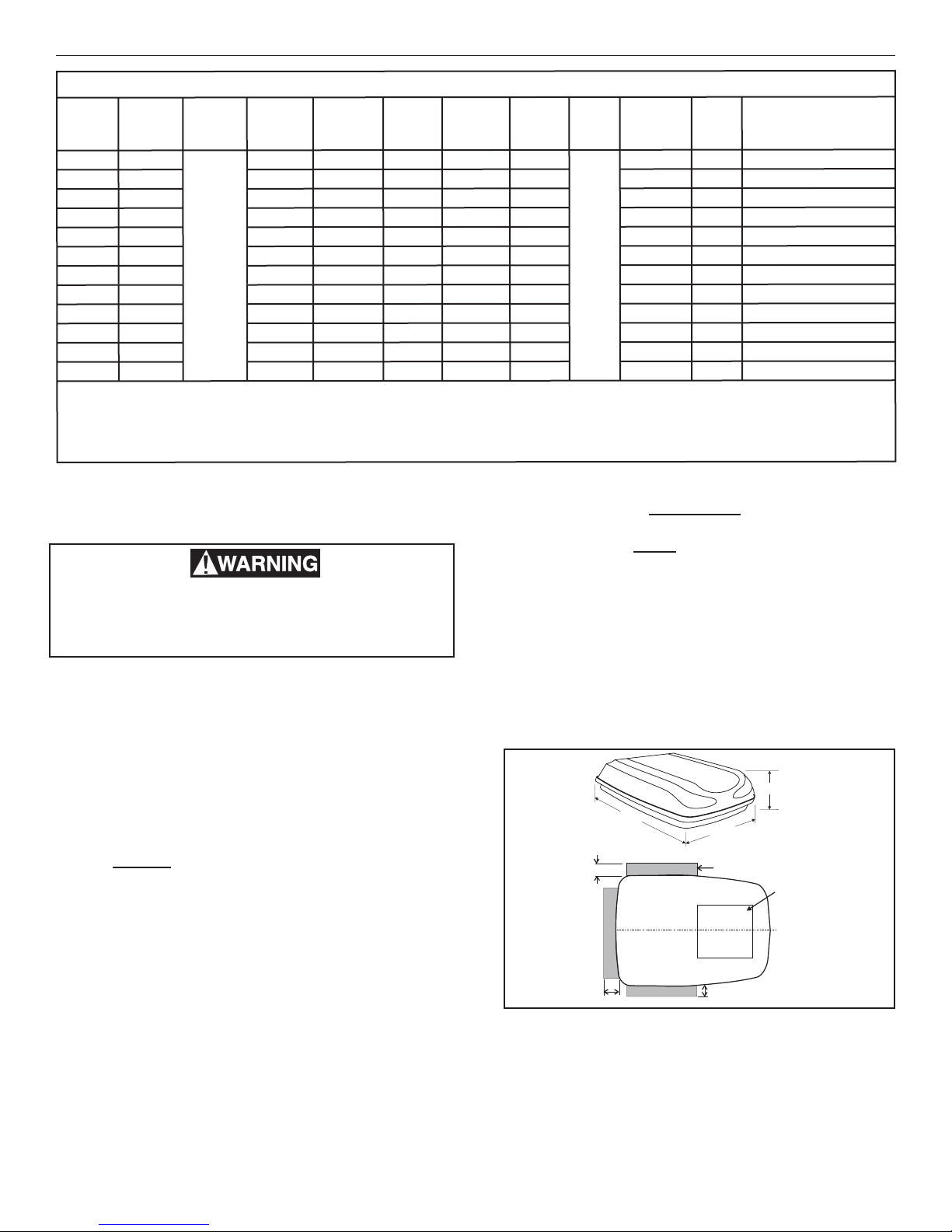
3. After Location Has Been Selected:
a. Check for obstructions in the area where unit
will be installed. See FIG 1.
FIG. 1
9-1/2"
12"
4"
40"
Center Line
Of Unit
29"
Keep these areas Free
of Obstructions
4"
14-1/4" x 14-1/4"
(±1/8") Opening
Front
Dimensions Are Nominal
b. The roof must be designed to support 130
pounds when the RV is in motion. Normally a
200 lb. static load design will meet this requirement.
3
641515, 641516, 641535, 651515 & 651516 Installation Instructions
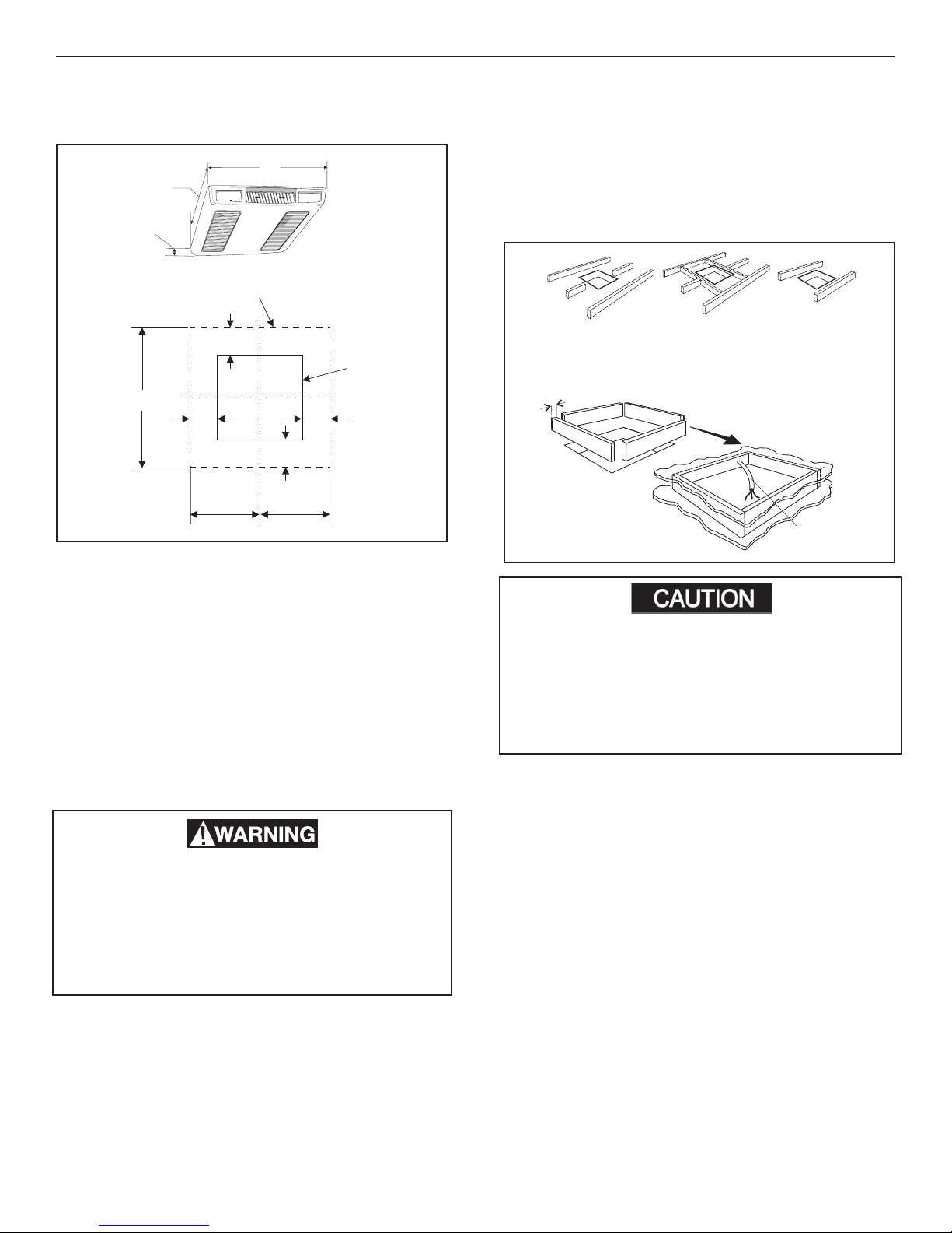
c. Check inside the RV for return air kit obstruc-
tions (i.e. door openings, room dividers, curtains, ceiling fi xtures, etc.) See FIG 2.
FIG. 2
Front
22"
2-1/2"
Perimeter Of Air Box
20"
3-7/8"
20"
2-7/8"
11" 11"
Dimensions Are Nominal
14-1/4" x 14-1/4" (±1/8")
Opening
Center Line Of
Opening
3-7/8"
C. Roof Preparation
1. Opening Requirements - Before preparing the ceiling opening, the type of system options must be
decided upon. Read all of the following instructions
before beginning the installation.
A 14-1/4" x 14-1/4" (±1/8") opening must be cut
through the roof and ceiling of the RV. This opening must be located between the roof reinforcing
members.
The 14-1/4" x 14-1/4" (±1/8") opening is part of the
return air system of the unit and must be fi nished
in accordance with NFP A Standard 501C Section
2.7.2.
There may be electrical wiring between the
roof and the ceiling. Disconnect 120 volt AC
power cord and the positive (+) 12 volt DC
terminal at the supply battery . Failure to follow
this instruction may create a shock hazard
causing death or severe personal injury.
2 New Opening
a. Mark a 14-1/4" x 14-1/4" (±1/8") square on the
roof and carefully cut the opening.
b. Using the roof opening as a guide, cut the
matching hole in the ceiling.
c. The opening created must be framed to provide
adequate support and prevent air from being
drawn from the roof cavity. Lumber 3/4" or
more in thickness must be used. Remember
to provide an entrance hole for power supplies, furnace wiring, 4-conductior control
cable, remote sensor and load shed (Energy
Management System) options as desired. See
FIG. 3.
FIG. 3
Do Not Cut
Roof Structure Or Raf-
3/4" Min.
Good-Rafters
Supported By
Cross Beams
Frame Opening So It
Won't Collapse When
Good LocationBetween Roof
Rafters
Bolting Down Unit
Leave Access For Power
Supply Wiring
15" Min. At
Front Of
Opening
It is the responsibility of the installer of this
unit to ensure structural integrity of the RV
roof. Never create a low spot on the roof where
water will collect. Water standing around the
unit may leak into the interior causing damage
to the product and the RV.
D. Wiring Requirements
1. 120 VAC Supply Line
Route a copper 12 AWG, with ground, 120 VAC
supply line from the time delay fuse or circuit breaker
box to the roof opening.
a. This supply line must be located in the front
portion of the 14-1/4" x 14-1/4" (±1/8") opening.
b. The power MUST be on a separate 20 Amp
time delay fuse or HACR circuit breaker.
c. Make sure that at least 15" of supply wire
extends into the roof opening. This ensures
and easy connection at the junction box.
d. Wiring must comply with all National, State
and Local Wiring Codes.
e. Use a steel sleeve and a grommet or equivalent
methods to protect the wire where it passes
into the opening.
2. Route a dedicated 12 VDC supply line (18-22
AWG) from the RV's converter (fi ltered terminals)
or battery to the roof opening.
4
 Loading...