

Dometic 620525.326, 620515.421, 620525.421, 620526.326, 620526.321 Installation Instructions Manual
...
USA
C
S
SERVICE OFFICE
Dometic Corporation
509 South Poplar Street
LaGrange, IN 46761
260-463-4858
RECORD THIS UNIT INFORMATION FOR
FUTURE REFERENCE:
Model Number
Serial Number
Date Purchased
MODELS
620515, 620525, 620526, 630515 &
630516
Roof Top Air Conditioner & Heat Pump
Used With
3105007 Return Air Kit
3105935 Quick Cool Return Air Kit
3308120 Genesis Air Filtration System Return Air Kit
3109228.001 Duo-Therm Comfort Control Center™
CANADA
Dometic Distribution
866 Langs Drive
Cambridge, Ontario
CANADA N3H 2N7
(519) 653-4390
For Service Center
Assistance Call:
800-544-4881
U
INSTALLATION
INSTRUCTIONS
REVISION
Form No. 3109530.067 2/04
(Replaces 3109530.059)
(French 3109884.068)
©2004 Dometic Corporation
LaGrange, IN 46761
This Unit Is Designed For OEM Installation. All Initial
Installations Must Be Approved By Dometic Corporation
This manual must be read and understood before installation, adjustment, service, or maintenance
is performed. This unit must be installed by a qualified service technician. Modification of this product
can be extremely hazardous and
could result in personal injury or
property damage.
Important: These Instructions
must stay with unit.
Owner read carefully.
1
Lire et comprendre ce manuel avant de
procéder à l'installation, à des réglages,
de l'entretien ou des réparations.
L'installation de cet appareil doit être
effectuée par un réparateur qualifié.
Toute modification de cet appareil peut
être extrêmement dangereuse et
entraîner des blessures ou dommages
matériels.
MODELS
620515.321
620515.326
620515.421
620525.321
620525.326
620525.421
620526.321
620526.326
630515.321
630515.326
630515.421
630516.321
630516.326

620515, 620525, 620526, 630515 & 630516 Installation Instructions
SAFETY INSTRUCTIONS
This manual has safety information and instructions to help users eliminate or reduce the risk of
accidents and injuries.
RECOGNIZE SAFETY INFORMATION
!
This is the safety-alert symbol. When you see this
symbol in this manual, be alert to the potential for
personal injury .
Follow recommended precautions and safe operating instructions.
UNDERSTAND SIGNAL WORDS
GENERAL INFORMATION
A. Product features or specifications as described or illus-
trated are subject to change without notice.
B. This air conditioner is designed for:
1. Installation on a recreational vehicle during the time
the vehicle is manufactured.
2. Mounting on the roof of a recreational vehicle.
3. Connection to an air distribution system located in
the ceiling/roof cavity of the recreational vehicle.
4. Roof construction with rafters/joists on minimum of
16 inch centers.
5. Minimum of 2.00" and maximum of 5.50" distance
between roof to ceiling of recreational vehicle. Alternate installation methods will allow for roofs more
than 5.50" thick.
C. The ability of the air conditioner to maintain the desired
inside temperature depends on the heat gain of the RV.
Some preventative measures taken by the occupants of
the RV can reduce the heat gain and improve the
performance of the air conditioner. During extremely high
outdoor temperatures, the heat gain of the vehicle may
be reduced by:
1. Parking the RV in a shaded area
2. Using window shades (blinds and/or curtains)
3. Keeping windows and doors shut or minimizing
usage
4. Avoiding the use of heat producing appliances.
A signal word , WARNING OR CAUTION is used
with the safety-alert symbol. They give the level of
risk for potential injury .
WARNING
!
indicates a potentially hazardous situation which, if not avoided, could result in
death or serious injury .
CAUTION
!
indicates a potentially hazardous situation which, if not avoided may result in
minor or moderate injury .
CAUTION
used without the safety alert
symbol indicates, a potentially hazardous situation which, if not avoided may result in property
damage.
Read and follow all safety information and instructions.
Operation on High Fan/Cooling mode will give optimum or
maximum efficiency in high humidity or high outside temperatures.
Starting the air conditioner early in the morning and giving it
a "head start" on the expected high outdoor ambient will
greatly improve its ability to maintain the desired indoor
temperature.
For a more permanent solution to high heat gain, accessories like A&E outdoor patio and window awnings will reduce
heat gain by removing the direct sun. They also add a nice
area to enjoy company during the cool of the evening.
D. Condensation
Note: The manufacturer of this air conditioner will not be
responsible for damage caused by condensed moisture on
ceilings or other surfaces. Air contains moisture and this
moisture tends to condense on cold surfaces. When air
enters the RV, condensed moisture may appear on the
ceiling, windows, metal parts, etc. The air conditioner removes this moisture from the air during normal operation.
Keeping doors and windows closed when this air conditioner
is in operation will minimize condensed moisture on cold
surfaces.
2
620515, 620525, 620526, 630515 & 630516 Installation Instructions
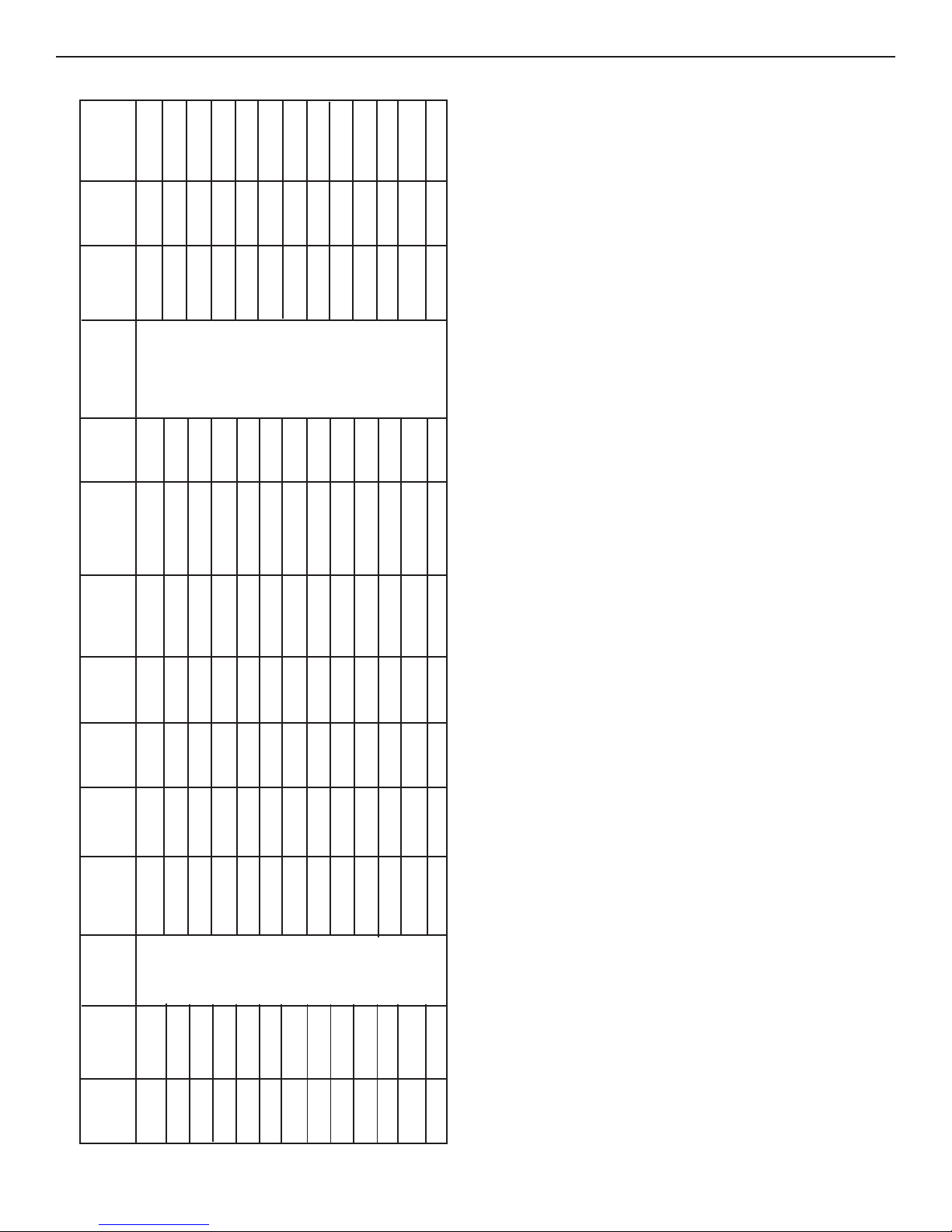
SPECIFICATIONS
Cooling Amps Amps W.C. Supplied 1Unit/2Units
(BTU/HR) Amps Rotor Amps Rotor Max/Min Max/Min ***User (Pounds) Size**
Model Nominal Electrical Compressor Compressor Fan Motor Fan Motor SCFM-High Total Refrigerant Minimum AC Circuit Installed Minimum
No. Capacity Rating Rated Load Locked Rated Load Locked Speed Static R-22 (Oz.) Wire Size* Protection Weight Generator
620515.321 13,500 115 VAC, 12.4 60.0 3.1 8.8 335 /250 0.12/0.65 15.5 12AWG 20 Amp 102 3.5 KW/5.0 KW
620515.326 13,500 60 Hz., 1 PH 12.4 60.0 3.1 8.8 335/250 0.12/0.65 15.5 Copper 20 Amp 10 2 3.5 KW/5.0 KW
620515.421 13,500 11.5 50.0 3.1 8.8 335/250 0.12 / 0.65 17.0 Up To 24' 20 Amp 102 3.5 KW/5.0 KW
620525.321 13,500 12.4 60.0 3.1 8.8 335 / 250 0.12/0.65 15.5 20 Amp 102 3.5 KW/5.0 KW
620525.326 13,500 12.4 60.0 3.1 8.8 335/250 0.12/0.65 15.5 20 Amp 102 3.5 KW/5.0 KW
620525.421 13,500 11.5 50.0 3.1 8.8 335/250 0.12/0.65 17.0 20 Amp 102 3.5 KW/5.0 KW
620526.321 15,000 12.0 64.0 3.3 8.5 380/250 0.12/0.65 21.5 20 Amp 104 3.5 KW/5.0 KW
620526.326 15,000 12.0 64.0 3.3 8.5 380/250 0.12/0.65 21.5 20 Amp 104 3.5 KW/5.0 KW
630515.321 13,500 12.4 60.0 3.1 8.8 335/250 0.12/0.65 24.5 20 Amp 102 3.5 KW/5.0 KW
630515.326 13,500 12.4 60.0 3.1 8.8 335/250 0.12/0.65 24.5 20 Amp 102 3.5 KW/5.0 KW
630515.421 13,500 12.0 50.0 3.1 8.8 335/250 0.12/0.65 19.5 20 Amp 102 3.5 KW/5.0 KW
630516.321 15,000 12.0 64.0 3.3 8.5 380/250 0.12/0.65 21.5 20 Amp 104 3.5 KW/ 5.0 KW
630516.326 15,000 12.0 64.0 3.3 8.5 380/250 0.12/0.65 21.5 20 Amp 104 3.5 KW/5.0 KW
When sizing the generator, the total power usage of your recreational vehicle must be considered. Keep in mind generators lose power at high altitudes
an dfrom lack of maintenance.
* For wire length over 24 ft., consult the National Electric Code for proper sizing.
** Dometic Corporation gives GENERAL guidelines for generator requirements. These guidelines come from experiences people have had in actual applications.
*** CIRCUIT PROTECTION: Time Delay Fuse or HACR Circuit Breakers Required.
3
CAUTION
M
i
c
r
o
-
T
h
e
r
m
F
i
l
t
e
r
S
y
s
t
e
m
Micro-Therm
Filter
System
F
I
L
T
E
R
R
E
S
E
T
FILTER
RESET
C
L
E
A
N
F
I
L
T
E
R
CLEAN
FILTER
620515, 620525, 620526, 630515 & 630516 Installation Instructions
INSTALLATION INSTRUCTIONS
A. Precautions
WARNING
!
Improper installation may damage equipment,
could endanger life, cause serious injury and/
or property damage.
1. Read Installation and Operating instructions carefully before attempting to start your air conditioner
installation.
2. Dometic Corporation will not be liable for any damages or injury incurred due to failure in following
these instructions.
3. Installation must comply with the National Electrical Code ANSI/NFPA-70 and CSA Standard C22.1
(latest edition) and any State or Local Codes or
regulations.
4. DO NOT add any devices or accessories to this air
conditioner except those specifically authorized by
Dometic.
5. This equipment must be serviced by qualified personnel and some states require these people to be
licensed.
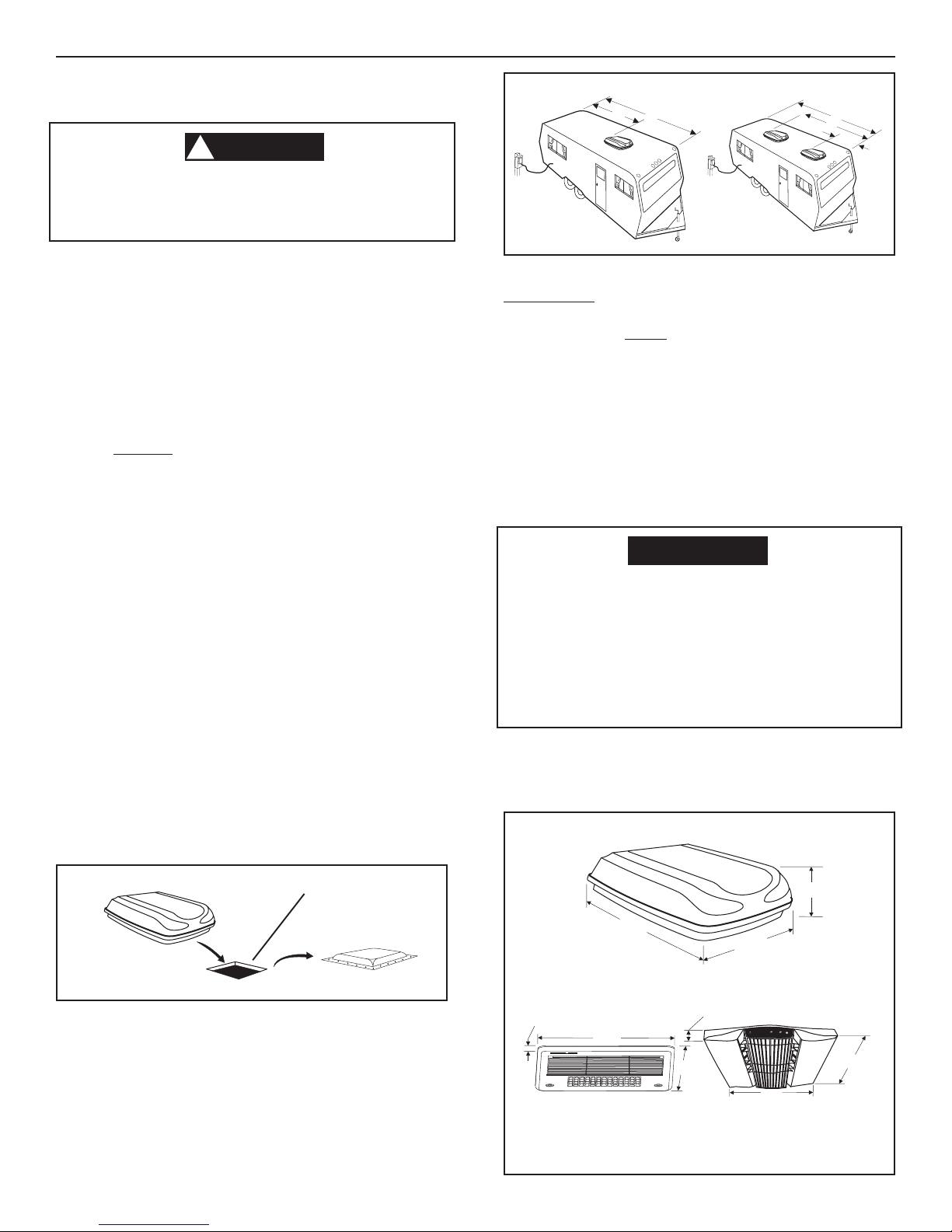
B. Choosing Proper Location For The Air
Conditioner
This air conditioner is specifically designed for installation on
the roof of a recreational vehicle (RV). When determining
your cooling requirements, the following should be considered:
• Size of RV;
• Window area (increases heat gain);
• Amount of insulation in walls and roof;
• Geographical location where the RV will be used;
• Personal comfort level required.
1. Normal Location-The air conditioner is designed to
fit over an existing roof vent opening. When the vent
is removed, it normally creates a 14-1/4" X 14-1/4"
(±1/8") opening.
FIG. 2
1/2 L
L
2/3 L
L
1/3 L
It is preferred that the air conditioner be installed in a relatively
flat and level roof section measured with the RV parked on
a level surface.
Note: A 8° slant to either side, or front to back, is acceptable
for 620515, 620525, 620526, 630515 and 630516 series.
3. After Location Has Been Selected:
a. Check for obstructions in the area where air
conditioner will be installed. See FIG. 3 & 4.
b. The roof must be designed to support 130
poundswhen the RV is in motion. Normally a
200 lb. static load design will meet this requirement.
It is the responsibility of the installer of this
air conditioner system to ensure structural integrity of the RV roof. Never create a low spot
on the roof where water will collect. Water
standing around the air conditioner may leak
into the interior causing damage to the product and the RV.
c. Check inside the RV for return air cover obstruc-
tions (i.e. door openings, room dividers, curtains, ceiling fixtures, etc.) See FIG. 3 & 4.
FIG. 3
FIG. 1
Roof Vent
Opening
2. Other Locations-When no roof vent is available or
another location is desired, the following is recommended:
a. For one unit installation: The air conditioner
should be mounted slightly forward of center
(front to back) and centered from side to side.
b. For two unit installations: Install one Air Condi-
tioner 1/3 and one Air Conditioner 2/3’s from
front of RV and centered from side to side.
9-1/2"
28-3/4"
39"
3/4"
2"
17"
17"
20-7/8"
18-1/2"
4
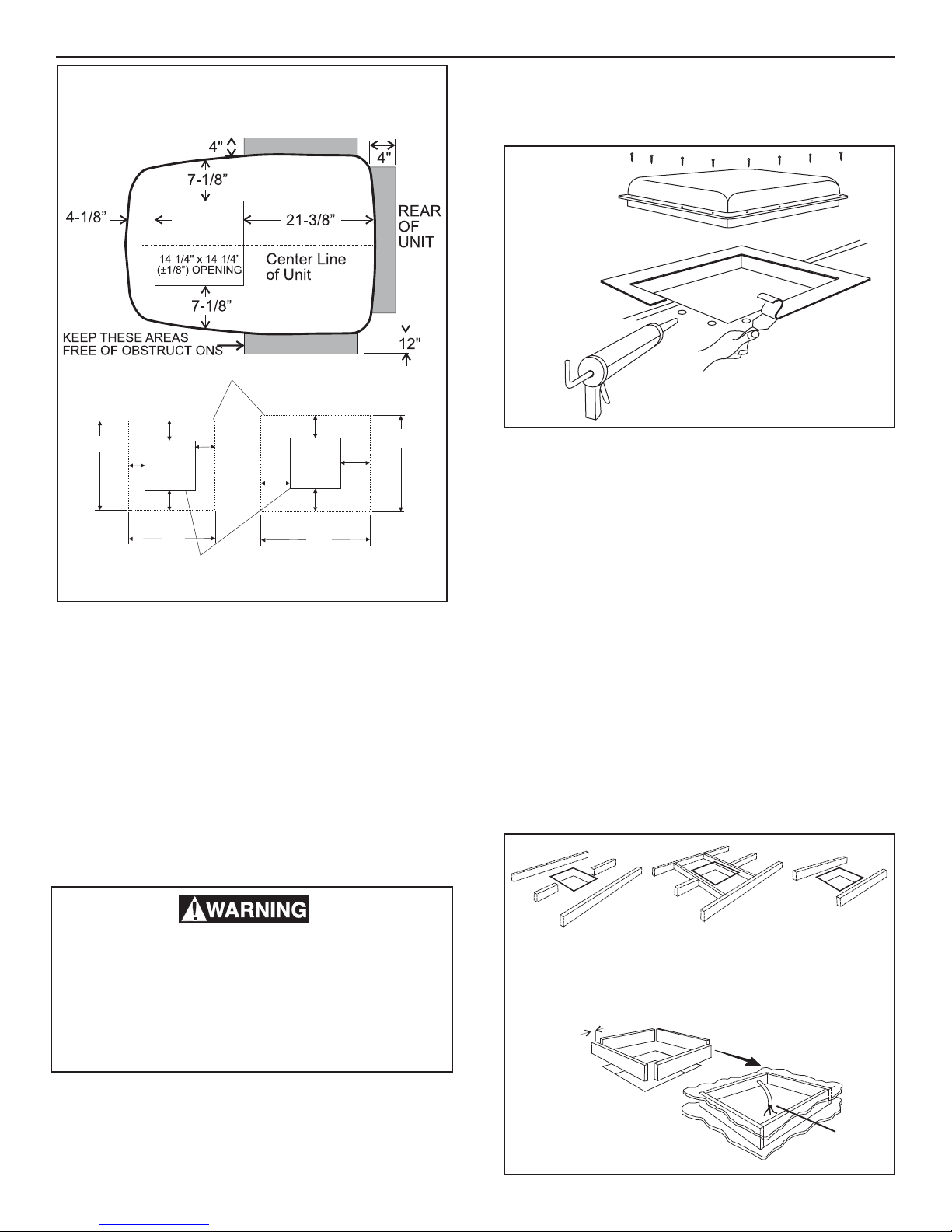
FIG. 4
AIR CONDITIONER DIMENSIONS
(On Top of Vehicle)
Air Grill Perimeter
620515, 620525, 620526, 630515 & 630516 Installation Instructions
2. Roof Vent Removal
a. Unscrew and remove the roof vent.
b. Remove all caulking compound around open-
ing.
FIG. 5
1-1/2"
17"
1-1/4"
1-1/2"
17"
1-3/4"
14-1/4 x 14-1/4 (±1/8")
3"
2"
3"
2"
20-7/8"
Genesis
Opening
C. Roof Preparation
1. Opening Requirments - Before preparing the ceiling
opening, the type of system options must be decided upon. If a remote sensor is to be used,
provision must be made for it. If the load shed option
is to be used, wires must be run from the load shed
control to the Dometic A/C. If a furnace is to be
connected, wires must be run from the furnace to the
Dometic A/C. Read all of the following instructions
before beginning the installation.
If a roof vent opening will not be used a 14-1/4" x 141/4" (±1/8") opening must be cut through the roof and
ceiling of the RV. This opening must be located
between the roof reinforcing members.
18-1/2"
c. Seal all screw holes and seams where the roof
gasket is located. Use a good grade of all
weather sealant.
d. If the opening exceeds 14-3/8" x 14-3/8", it will
be necessary to install spacers.
e. If the opening is less than 14-1/8" x 14-1/8", it
must be enlarged.
3. New Opening-(Installation Other Than Vent Opening)
a. Mark a 14-1/4" x 14-1/4" (±1/8") square on the
roof and carefully cut the opening.
b. Using the roof opening as a guide, cut the
matching hole in the ceiling.
d. The opening created must be framed to provide
adequate support and prevent air from being
drawn from the roof cavity. Lumber 3/4" or more
in thickness must be used. Remember to provide an entrance hole for power supplies, furnace wiring, 4-conductor control cable, remote
sensor and load shed (Energy Management
System) options as desired.
FIG. 6
There may be electrical wiring between the
roof and the ceiling. Disconnect 115 volt AC
power cord and the positive (+) 12 volt DC terminal at the supply battery. Failure to follow
this instruction may create a shock hazard
causing death or severe personal injury.
The 14-1/4" x 14-1/4" (±1/8") opening is part of the
return air system of the Air Conditioner and must be
finished in accordance with NFPA Standard 501C
Section 2.7.2.
Do Not Cut
Roof Strucure
Or Rafters
Leave Access For
Power Supply Wiring
5
Good-Rafters
Supported By
Cross Beams
3/4" Min.
Good LocationBetween Roof
Rafters
Frame Opening So It
Won't Collapse When
Bolting Down
15" min.
CAUTION
CAUTION
CAUTION
It is the responsibility of the installer of this
air conditioner system to ensure structural
integrity of the RV roof. Never create a low
spot on the roof where water will collect. Water standing around the air conditioner may
leak into the interior causing damage to the
product and the RV.
4. Air Distribution System Sizing & Design (See Chart
On Page 7)
CAUTION
It is the responsibility of the installer to insure
the ductwork will not collapse or bend during
and after the installation. Dometic Corporation
will not be liable for roof structural or ceiling
damage due to improperly insulated, sealed
or collapsed ductwork.
The Installer of this air conditioner system must design
the air distribution system for this particular application.
Several requirements for this system MUST be met for
the air conditioner to operate properly. These requirements are as follows:
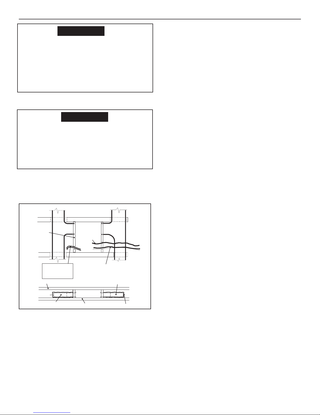
FIG. 7
FRAME
INSULATION
DUCT
LOW VOLTAGE WIRES:
12VDC
Furnace
Load Shed
Sensors
ROOF
(TOWARD BACK OF RV)
DUCT
a. The duct material must meet or exceed any
agency or RVIA Standard that may be in existence at the time the RV is produced.
b. All discharge air ducts must be properly insu-
lated to prevent condensation from forming on
their surfaces or adjacent surfaces during operation of the air conditioner. This insulation
must be R-7 minimum.
c. Ducts and their joints must be sealed to prevent
condensation from forming on adjacent surfaces during operation of the air conditioner.
d. Return air openings must have 40 square inches
minimum free area including the filter.
TOP VIEW
(BACK OF RV)
FRAME
14-1/4" (±1/8”)
OPENING
AC POWER
SUPPLY WIRE
FRAME
CCC, CONTROL CABLE(S)
or 7-Wire Analog Cable
SIDE VIEW
14-1/4" (±1/8”)
OPENING
CEILING
DUCT
DUCT
INSULATION
620515, 620525, 620526, 630515 & 630516 Installation Instructions
e. Return air to the air conditioner must be filtered
to prevent dirt accumulation on air conditioner
cooling surface.
5. Air Distribution System Installation
a. Dometic Corporation recommends the basic
configuration shown on page 8, for installing this
air conditioner system. We have found by testing, that this configuration works best in most
applications of this air conditioner system. It is
the responsibility of the Installer of this system
to review each RV floor plan and determine the
following:
• Duct size
• Duct layout
• Register size
• Register location
• Thermostat location
These items must be determined in conjunction with the
Air Distribution System and Sizing and Design Requirements listed in the chart on page7. Terminate the start
of the duct at the back edge of the 14-1/4" x 14-1/4" (±1/
8" opening)
Important: Alternate configurations and methods
may be used which still allow the air conditioner to
operate properly; however, these alternate configurations and methods must be approved by the Dometic
Corporation in writing. The following instructions are
based upon the use of Dometic Return Air Kits
3105007.XXX, 3105935.XXX, or 3308120.XXX Genesis
Air Filtration System. The 3107180.006 Bolt/Cover Kit
has the mounting bolts and cover for the AC junction
box for use with these kits.
D. Wiring Requirments
1. Route a copper 12 AWG, with ground, 115 VAC
supply line from the fuse or circuit breaker box to the
roof opening.
a. This supply line must be located in the front
portion of the 14-1/4" x 14-1/4" (±1/8") opening.
b. The power MUST be on a separate 20 amp time
delay fuse or HACR circuit breaker.
c. Make sure that at least 15" of supply wire
extends into the roof opening. This ensures
easy connection at the junction box.
d. Wiring must comply with all National, State and
Local Wiring Codes.
e. Use a steel sleeve and a grommet or equivalent
methods to protect the wire where it passes into
the opening.
2. Route a dedicated 12 VDC supply line (18-22 AWG)
from the RV's converter or battery to the roof opening.
a. This supply line must be located in the front
portion of the 14-1/4" x 14-1/4" (±1/8") opening.
b. Make sure that at least 15" of supply wire
extends into the roof opening.
c. In a multiple zone installation, this wiring is
required in only one of the 14-1/4" x 14-1/4"
(±1/8") openings.
6
 Loading...