

Page 1
Fan
Cool
Furnace
*Heat
Pump or
Heat Strip
˚F
On/Off
Mode
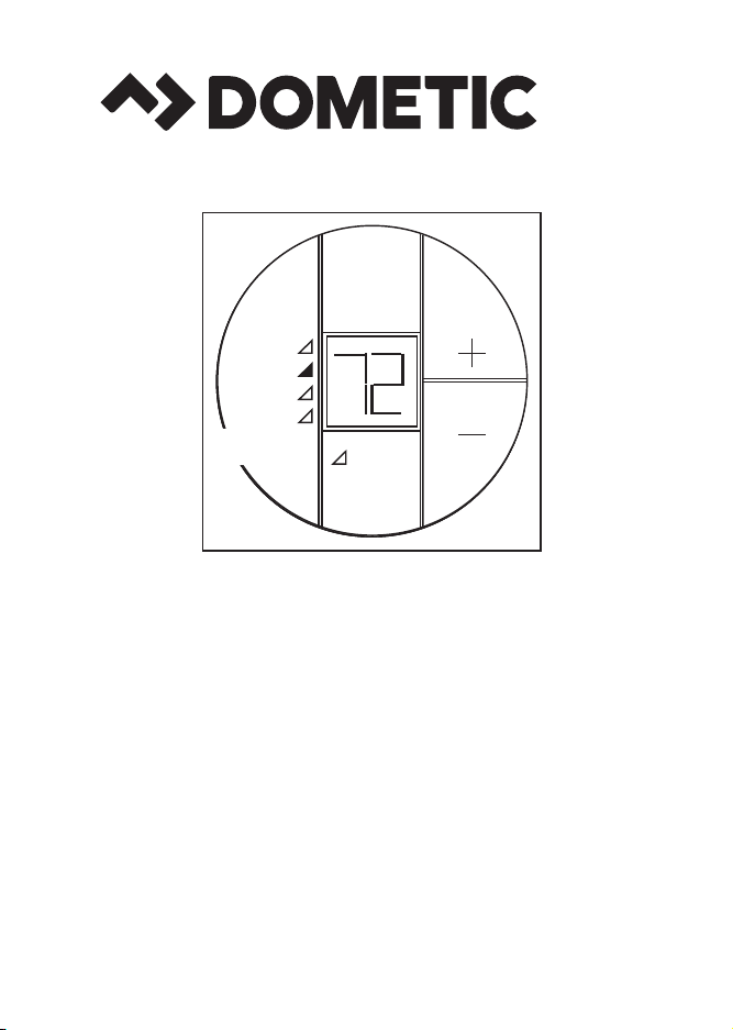
Single Zone LCD Thermostat
Operating Instructions
MODEL
3313192.XXX Cool/Furnace
3313193.XXX Cool/Furnace/Heat Pump
3313194.XXX Cool/Furnace/Heat Strip
REVISION A
Form No. 3313327.045 08/16
(Replaces 3313327.037)
(French 3313345.047_A)
©2016 Dometic Corporation
LaGrange, IN 46761
Page 2

TABLE OF CONTENTS
About Your New Thermostat
Features ..................................................................................................3
System Initialization .................................................................................3
Factory Preset Settings ...........................................................................4
Quick Reference To Control Buttons .......................................................4
Programming & Operations
On/Off ......................................................................................................5
Temperature Format ºF / ºC.....................................................................5
Inside Temperature ..................................................................................6
Mode Selection ........................................................................................6
Fan Speed ...............................................................................................7
Temperature Set-Point.............................................................................7
Mode Description
Off ..........................................................................................................8
Cool .........................................................................................................8
Furnace ...................................................................................................8
Heat Pump...............................................................................................9
Heat Strip.................................................................................................10
Fan ..........................................................................................................10
Special Features
Auto Fan ..................................................................................................11
Compressor Time Delay ..........................................................................11
Defrost Cycle ...........................................................................................11
Low Ambient Heat Pump Lock Out..........................................................12
Power Interruption ...................................................................................12
LCD Error Codes .....................................................................................12
General Information ..............................................................................13
Maintenance ...........................................................................................13
Service ....................................................................................................14
2
Page 3

About Your New Thermostat
Congratulations! Your recreational vehicle manufacturer has equipped
your RV with the most advanced RV thermostat. Your Dometic Single
Zone LCD thermostat has been designed for ease of operation and for
many years of reliable service.
Features
• Liquid Crystal Display and Green LED Mode Indicators
• Auto Fan
• Indoor Temperature Display
• °F / °C Display
• Air conditioner can provide additional indoor air circulation during
furnace operation.
To help familiarize yourself with the operation of the Single Zone LCD
thermostat, review the following diagrams and accompanying text that
explain the functional characteristics of this system.
Your Single Zone LCD thermostat is equipped with both a liquid crys-
tal display (LCD) that identies the temperature set-point, fan speed
(Auto, Low, High), and F/C and green LEDs that indicate the mode of
operation (Off, Fan, Cool, Furnace, Heat Pump or Heat Strip*). The
modes of operation available will vary depending on the system installed in your RV.
* Select models.
System Initialization
A system initialization will need to be performed by the installer after
the system is installed.
• Make sure the Single Zone LCD thermostat is in the Off condi-
tion. See page 4, “Quick Reference To Control Buttons”.
• Press the “+” button and, while holding it, also press and hold
the On/Off Mode button for three seconds. LCD will show
― ― . Press the On/Off Mode button again to turn system off.
This completes the initialization.
The furnace On/Off temperature differential should be set at this time.
See “Mode Description - Furnace” on page 8 for further information
on furnace mode differential setting.
3
Page 4
Your Dometic Single Zone LCD thermostat has been pre-programmed. Review settings below and adjust the settings to your
personal comfort level.
Factory Preset Settings
Heating 68 ºF / 20 ºC
Cooling 72 ºF / 22 ºC
Fan Speed Auto
Mode Off
Furnace Differential 2 ºF
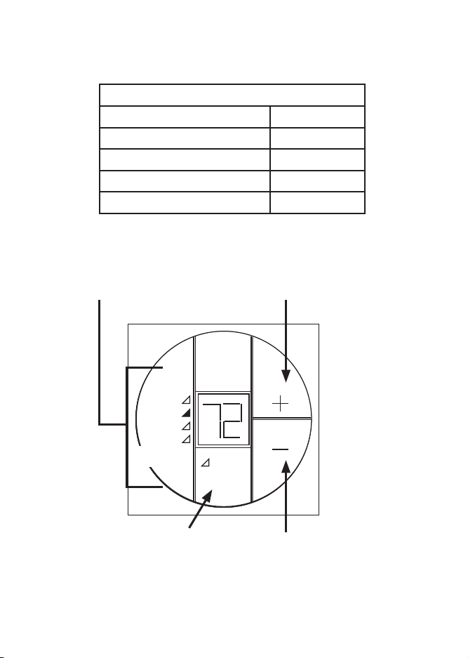
Quick Reference To Control Buttons
Indicates mode of operation
when illuminated
Furnace
Pump or
Heat Strip
* Select Models
Press to select
mode of operation
Fan
Cool
*Heat
On/Off
Mode
Press to increase
temperature set-point
˚F
Press to decrease
temperature set-point
4
Page 5
Programming & Operations
On/Off
To turn On the Single Zone LCD thermostat, press the On/Off Mode
button. The LCD will be activated. To turn Off the Single Zone LCD
thermostat press the On/Off Mode button and toggle through the
modes until the On/Off green LED is on. The LCD will go out and
the green LED will remain on for approximately 15 seconds, then
go out.
Temperature Format ºF / ºC
Simultaneously press the “+” and “―“ buttons to toggle between
Fahrenheit and Centigrade format. ºF indicates Fahrenheit and ºC
indicates Centigrade.
Fan
Cool
Furnace
*Heat
Pump or
Heat Strip
On/Off
Mode
˚F
5
Page 6

Inside Temperature
On/Off
Mode
Fan
Cool
Furnace
˚F
To display the Inside Temperature, the Single Zone LCD thermostat
must be in the Off Mode. Press either the “+” or “―” button to display the Inside Temperature.
Mode Selection
Press the On/Off Mode button to advance through the available
modes. Each successive press will advance to the next available
mode. The green LED will indicate the mode selected. Depending
on the systems installed, your choices will be Off, Fan, Cool, Furnace, Heat Pump or Heat Strip. See “Mode Description” on pages
8-10 for more information on modes.
Fan
Cool
Furnace
On/Off
Mode
˚F
6
Page 7

Fan Speed
Press the On/Off Mode button until the fan green LED is lit. The
LCD will show “Lo” (Low), “Hi” (High) or “Au” (Auto). Press the “+” or
“―” button to select the desired fan speed. See “Special Features”
on page 11 for more information on Auto Fan.
Fan
Cool
Furnace
On/Off
Mode
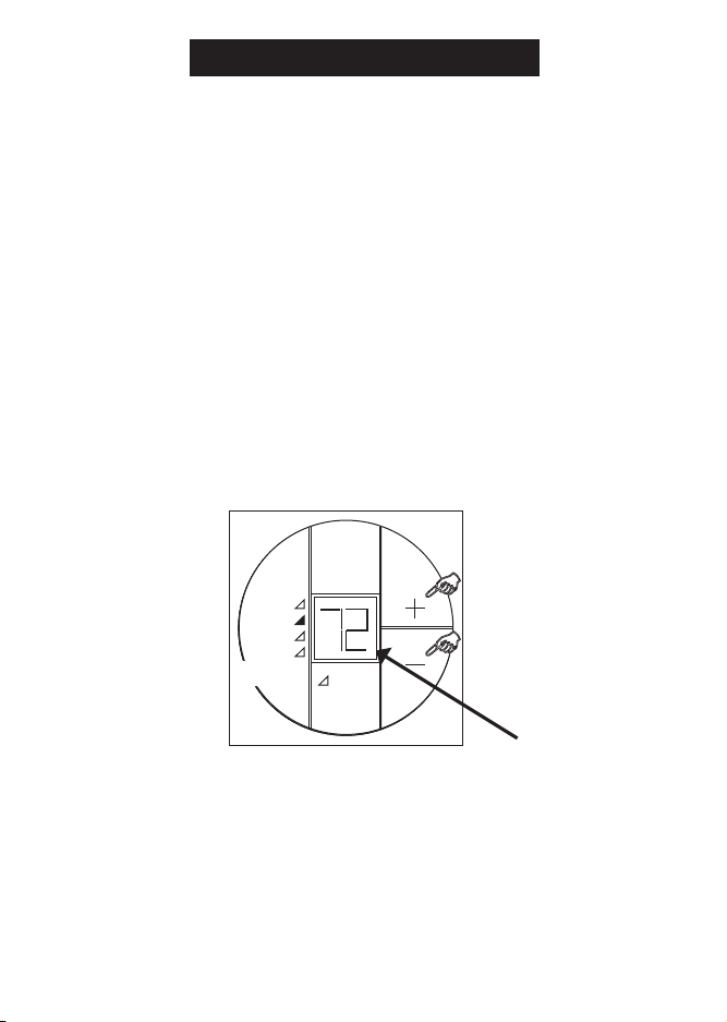
Temperature Set-Point
Press the “+” or “―” button to change the temperature set-point. The
temperature set-point is indicated by two digits on the LCD. Press
the “+” to increase or the “―” to decrease the temperature set-point.
The maximum set-point for the system is 90 ºF. The minimum setpoint is determined by the active operating mode. For heating, the
minimum is 40 ºF and minimum for cooling is 55 ºF.
Cool
Furnace
*Heat
Pump or
Heat Strip
Fan
On/Off
Mode
7
˚F
Page 8

Mode Description
“Off” - Off Mode
When selected, the LCD will be blank and the Off green LED will
turn on for 15 seconds, then it will turn off.
“Cool” - Cool Mode
In the Cool Mode the system will cycle the compressor On and Off
based on the room air temperature and the temperature set-point on
the Single Zone LCD thermostat. The fan will turn on rst followed
by the compressor in approximately 2 minutes. In this mode there
are 3 fan speed selections:
Lo - (LOW): The fan operates continuously at low speed. The compressor cycles On and Off.
Hi - (HIGH): The fan operates continuously at high speed. The compressor cycles On and Off.
Au - (AUTO): When auto fan is selected the fan speed will vary
depending on the difference between the temperature set-point and
the room air temperature. In auto fan the compressor and the fan
will cycle On and Off with the thermostat. See “Special Features”
on page 11 for more information on auto fan.
“Furnace” - Furnace Mode
In this mode there are 3 fan speed selections:
Lo - (LOW): The fan operates continuously at low speed.
Hi - (HIGH): The fan operates continuously at high speed.
Au - (AUTO): The fan will be Off.
Note: If additional indoor air circulation provided by the air conditioner is not desired during Furnace Mode of operation, select Au
(AUTO) in the Fan Mode to shut the air conditioner fan off. If Lo
(LOW) or Hi (HIGH) is selected the air conditioner fan will continue
to operate on the selected speed.
8
Page 9

In the FURNACE Mode the system will cycle the RV’s furnace On
and Off based on the room air temperature and the temperature setpoint on the Single Zone LCD thermostat. The system can be congured to operate using an On/Off differential of either 1 degree F
or 2 degree F. This feature is programmed during the system initialization. See “System Initialization” on page 3.
To set the temperature differential the system must be Off. Press
the “―” button and, while holding it, also press and hold the On/Off
Mode button for three seconds. Release the On/Off Mode button.
Then release the “―” button. Press the “+” button to toggle between
“d1” and “d2”, “d1” for 1 degree F differential and “d2” for 2 degrees F differential.
“Heat Pump” - Heat Pump Mode (Select Models)
Heat Pump Operation: This mode of operation is customer chosen
and is usually selected when temperatures are below 70 °F and the
customer needs warmth in the living space rather than cool down.
This reverses the refrigerant ow in the air conditioner and causes
the inside air to dispense warm air rather than cold and the outside
air to dispense cold air rather than warm.
This mode of operation creates a dilemma where the outside coil
which is now dispensing cold air can freeze up due to the cold air
blowing across the coil mixed with the outside temperature. A freeze
up of the system can render your heat pump inoperable. Therefore,
we have a defrost feature that will prevent this from happening. See
"Special Features", on page 11 for more information on defrost
cycle.
9
Page 10

In the Heat Pump Mode the system will cycle the compressor On
and Off based on the room air temperature and the temperature setpoint on the Single Zone LCD thermostat. When the system calls for
heating there will be a delay of approximately two minutes. In auto
fan, the compressor will turn On rst followed by the fan in approximately 15 seconds. In this mode there are 3 fan speed selections:
Lo - (LOW): The fan operates continuously at low speed. The compressor cycles On and Off.
Hi - (HIGH): The fan operates continuously at high speed. The compressor cycles On and Off.
Au - (AUTO): When auto fan is selected the fan speed will vary
depending on the difference between the temperature set-point and
the room temperature. In auto fan the compressor and fan will cycle
On and Off with the thermostat. The compressor shuts off rst fol-
lowed by the fan in approximately 15 seconds. See “Special Fea-
tures” on page 11 for more information on auto fan.
“Heat Strip” - Heat Strip Mode (Select Models)
In the Heat Strip Mode the system will cycle the heat strip On and
Off based on the room air temperature and the temperature set-
point on the Single Zone LCD thermostat. In this mode there are 3
fan speed selections:
Lo - (LOW): The fan operates continuously at low speed. The heat
strip cycles On and Off.
Hi - (HIGH): The fan operates continuously at high speed. The heat
strip cycles On and Off.
Au - (AUTO): The fan operates in low speed and will cycle On and
Off with the thermostat.
“Fan” - Fan Mode
In Fan Mode there are 3 fan speed selections:
Lo - (LOW): The fan operates continuously at low speed.
Hi - (HIGH): The fan operates continuously at high speed.
Au - (AUTO): The fan will be Off.
10
Page 11

Special Features
Auto Fan
When auto fan is selected the fan speed will vary depending on the
difference between the temperature set-point and the room temperature. In auto fan the compressor and fan cycle On and Off with the
thermostat.
When the difference is:
>5º The fan operates on HIGH
<4º The fan operates on LOW
Compressor Time Delay
A time delay of approximately two minutes occurs any time the compressor is required to begin the cooling or heat pump cycle.
Defrost Cycle
During heat pump operation, if the outside coil begins to freeze
up, a defrost cycle is initiated that temporarily puts the heat pump
back into air conditioning mode. This reverses the refrigerant ow
and melts the ice forming on the outside coil. Typically this occurs when the outside temperatures are below 42 °F and repeats
every 25 minutes of compressor run time as long as the outside
temperature stays below 42 °F and above 30 °F. Therefore, during this period of operation you, (the user) will temporarily feel
cold air inside the RV at the registers. This is normal and is NOT
an indication of malfunction. (Note: Defrost cycling shall continue until the measured temperature of the Outdoor Sensor is
≤30 °F or ≥42 °F.)
11
Page 12

Low Ambient Heat Pump Lock Out
All heat pumps are constrained to operation at a temperature range
that is determined by outside conditions. Since all heat pumps lose
their efciency at low outside ambient temperatures, the Dometic
heat pump has a lock out feature that prevents heat pump mode
of operation when temperatures fall below 30 °F. If you have the
system set in the Auto Mode the fan will be turned OFF. Only the
fan will remain ON if the fan setting is set at Low or High, however
the compressor will not run and there will be no heat function below
30 °F.
Power Interruption
In the event the power to the air conditioner or control is interrupted,
the system will restart with the previous set points once power is
restored.
LCD Error Code
When the system determines that one of the faults listed below has occurred an error
code will be displayed in the LCD.
Error Code:
E1 Loss of communication between the Single Zone LCD thermostat and the mod-
ule board. LCD will cycle between E1 and the previous mode setting. System
will shut down.
E2 Open circuit or out of range Indoor Temperature Sensor. Heating and cooling
operation will be locked out. Fan operation can continue to operate.
E3 Shorted Indoor Temperature Sensor. Heating and cooling operation will be
locked out. Fan operation can continue to operate.
E4 Open circuit or out of range Outdoor Temperature Sensor (select models). Heat
Pump operation will be locked out. Air Conditioner, Fan and Furnace operation
can continue to operate.
E5 Open circuit or out of range Freeze Sensor. Air conditioner mode of operation
will be locked out. Furnace, heat strip, heat pump and fan mode of operation can
continue to operate but displays the last temperature set-point.
12
Page 13

General Information
A. The ability of the air conditioner to maintain the desired inside tempera-
ture depends on the heat gain of the RV. Some preventative measures
taken by the occupants of the RV can reduce the heat gain and improve
the performance of the air conditioner. During extremely high outdoor
temperatures, the heat gain of the vehicle may be reduced by:
1. Parking the RV in a shaded area
2. Using window shades (blinds and/or curtains)
3. Keeping windows and doors shut or minimizing usage
4. Avoiding the use of heat producing appliances
Operation on High Fan/Cooling mode will give optimum or maximum
efciency in high humidity or high outside temperatures.
Starting the air conditioner early in the morning and giving it a "head
start" on the expected high outdoor ambient will greatly improve its ability
to maintain the desired indoor temperature.
For a more permanent solution to high heat gain, accessories like Dometic
outdoor patio and window awnings will reduce heat gain by removing
the direct sun. They also add a nice area to enjoy company during the
cool of the evening.
B. The manufacturer of this air conditioner will not be responsible for dam-
age caused by condensed moisture on ceilings or other surfaces. Air
contains moisture and this moisture tends to condense on cold surfaces.
When air enters the RV, condensed moisture may appear on the ceiling,
windows, metal parts, etc. During normal operation, this unit removes
moisture from the air. Keeping doors and windows closed when this air
conditioner is in operation will minimize condensed moisture on cold
surfaces.
Maintenance
Air Filter - Periodically (a minimum of every 2 weeks of operation) remove
the return air lter located behind the return air grille and wash the lter with
soap and warm water, let dry, and then reinstall. NEVER run the air condi-
tioner without the air lter in place. This will plug the unit evaporator coil with
dirt and may substantially degrade the performance of the unit over time.
Dometic Single Zone LCD thermostat: Clean the Single Zone LCD thermostat with a moist soft cloth. DO NOT spray water directly on the Single
Zone LCD thermostat. DO NOT use solvents for cleaning.
13
Page 14

Service
In the unlikely event the unit fails to operate or operates improperly,
check the following before calling your service center.
1. If your RV is connected to a motor generator, check to be sure
the motor generator is running and producing power.
2. If the RV is connected to a power supply by a land line, check to
be sure the line is sized properly to run air conditioner load and
it is plugged into the power supply.
3. Check your 120 Vac fuse or circuit breaker to see if it is open.
4. Check your 12 Vdc fuse or circuit breaker to see if it is open.
5. After the above checks, call your local service center for further
help. This unit must be serviced by qualied service personnel
only.
When calling for service, always give the following:
1. Air conditioner/heat pump Model Number and Serial Number
found on Identication Label located on the Base Pan of the
unit. It is necessary to remove the return air cover to expose the
rating plate.
2. Electronic Control Kit Part Number and Serial Number found
on Identication Label located on the side of the Kit. This kit is
mounted in the return air cavity and can be exposed by removing the return air cover.
USA
SERVICE OFFICE
Dometic Corporation
1120 North Main Street
Elkhart, IN 46514
CANADA
Dometic Corporation
46 Zatonski, Unit 3
Brantford, ON N3T 5L8
CANADA
14
For Service Center
& Dealer Locations:
Please Visit:
www.eDometic.com
 Loading...