

Page 1
EN
DEFRESPTIT
NL
DASVNOFIRUPLSKCSHU
WINDOWS & DOORS
BLINDS
Mini-dubbel-cassetterolgordijn
Montagehandleiding en
gebruiksaanwijzing. . . . . . . . . . . . . . . . . . . 46
Mini-dobbelt-kassetterullegardin
Monterings- og betjeningsvejledning. . . . 52
Mini-dubbel-kassettrullgardin
Monterings- och bruksanvisning . . . . . . . . 58
Mini-dobbel-rullegardinkassett
Monterings- og bruksanvisning. . . . . . . . . 64
Mini-double cassette roller blind
Installation and Operating Manual. . . . . . . . 9
Mini-Doppel-Kassettenrollo
Montage- und Bedienungsanleitung . . . . . 15
Mini store double à cassette
Instructions de montage
et de service . . . . . . . . . . . . . . . . . . . . . . . . .22
Estor de cajón doble mini
Instrucciones de montaje y de uso. . . . . . .28
Mini-persiana dupla
Instruções de montagem e manual de
instruções . . . . . . . . . . . . . . . . . . . . . . . . . . .34
Mini-kaksoiskasettirullakaihdin
Asennus- ja käyttöohje . . . . . . . . . . . . . . . . 70
Двойная кассетная мини-ролета
Инструкция по монтажу и эксплуатации . 76
Podwójna roleta kasetowa mini
Instrukcja montażu i obsługi. . . . . . . . . . . . 83
Mini dvojkazetová roleta
Návod na montáž a uvedenie
do prevádzky. . . . . . . . . . . . . . . . . . . . . . . . 89
Miniaturní dvojitá kazetová roleta
Návod k montáži a obsluze . . . . . . . . . . . . 95
Mini dupla kazettás redőny
Szerelési és használati útmutató . . . . . . . 101
Cassetta avvolgibile doppia mini
Istruzioni di montaggio e d’uso . . . . . . . . .40
Page 2
Page 3
Dometic
1
2
3
4
1
3
Page 4
7
5
1
3
3
2
4
4
6
2
Dometic
4
Page 5
Dometic
=
90°
=
=
=
3
4
5
Ø 2 mm
5
Page 6
Dometic
6
B
7
6
2
3
F
B
1
Page 7

Dometic
Ø 2 mm
B
B1
B1
1
1. 2. 3. 4. 5.
8
9
1
3
2
0
3
1
1.
1.
2.
3.
2
7
Page 8
Dometic
1
2
3
a
18
C
A
36
E
D
B
F
b
8
Page 9

EN
Dometic Scope of delivery
Please read this instruction manual carefully before installation and first
use, and store it in a safe place. If you pass on the product to another
person, hand over this instruction manual along with it.
Contents
1 Scope of delivery . . . . . . . . . . . . . . . . . . . . . . . . . . . . . . . . . . . . . . . . . . . . . . .9
2 Intended use . . . . . . . . . . . . . . . . . . . . . . . . . . . . . . . . . . . . . . . . . . . . . . . . . . .9
3 Fitting the blind . . . . . . . . . . . . . . . . . . . . . . . . . . . . . . . . . . . . . . . . . . . . . . . .10
4 Using the blind . . . . . . . . . . . . . . . . . . . . . . . . . . . . . . . . . . . . . . . . . . . . . . . .12
5 Troubleshooting . . . . . . . . . . . . . . . . . . . . . . . . . . . . . . . . . . . . . . . . . . . . . . .13
6 Cleaning and maintenance. . . . . . . . . . . . . . . . . . . . . . . . . . . . . . . . . . . . . . .13
7 Warranty . . . . . . . . . . . . . . . . . . . . . . . . . . . . . . . . . . . . . . . . . . . . . . . . . . . . .13
8 Technical data . . . . . . . . . . . . . . . . . . . . . . . . . . . . . . . . . . . . . . . . . . . . . . . . .14
1Scope of delivery
No. in
fig. 1, page 3
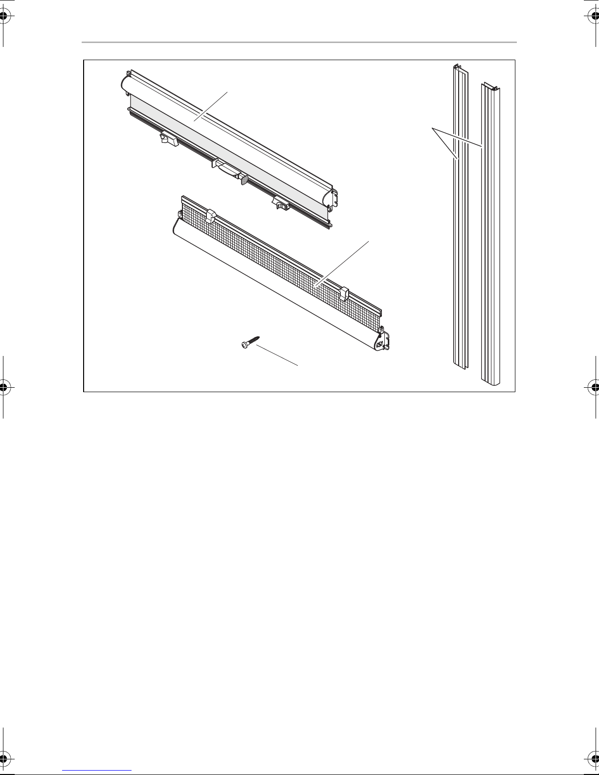
1 1 Blackout roller blind cassette
2 1 Flyscreen roller blind cassette
3 2 Guide rails
4 12 Fastening screws
Quantity Description
2 Intended use
The Mini-double cassette roller blind is suitable for windows in motorhomes or
caravans. It has a flyscreen blind and a blackout blind.
9
Page 10
EN
Fitting the blind Dometic
3 Fitting the blind
➤ Before installing the blind, check whether there is enough space for the blind.
The guide rails can be shortened if necessary (see chapter “Shortening the guide
rails” on page 11).
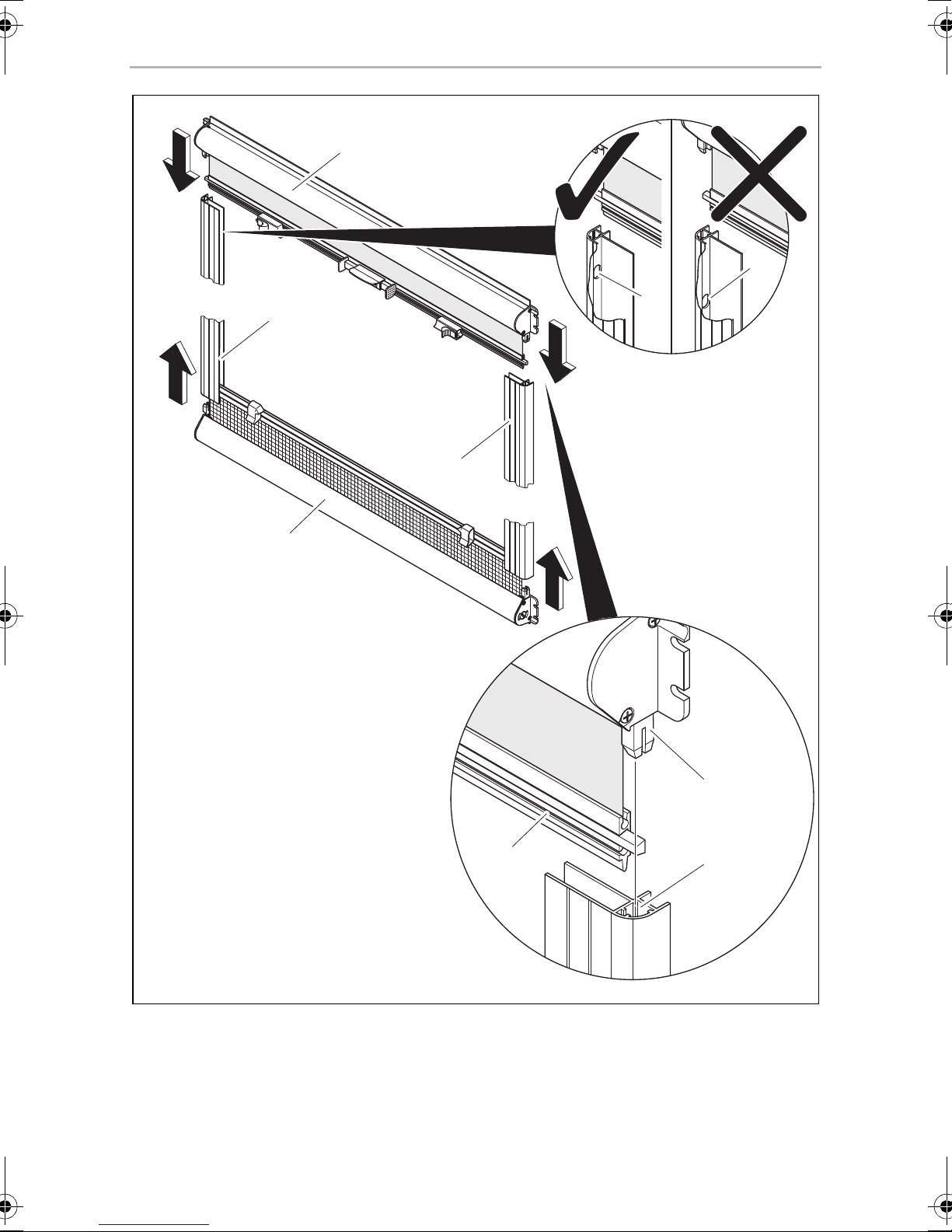
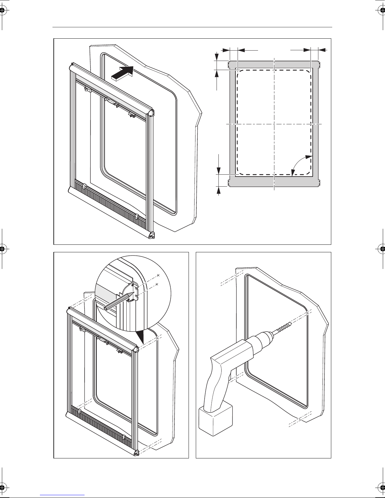
Fit the roller blind cassettes together (fig. 2, page 4)
➤ Align the individual parts as shown.
You must align the mortise ends with the short distance to the slots (4) with the
tenons of the blackout blind.
➤ Fit the two roller blind cassettes (1) and (2) and the two guide rails (3) together to
form a closed frame:
– Thread the handle strip (5) of the blinds into the guide rails.
– Insert the tenons (6) into the mortises (7).
Fixing the blind
NOTE
I
➤ Align the frame as follows on the window (fig. 3, page 5):
– The distance to the rubber profile of the window on the left and on the right
– The roller blind cassettes must run parallel to the upper and lower edges of
– The guide rails must be at right angles to the roller blind cassettes
I
➤ Mark the fixing holes in the support covers on the wall (fig. 4, page 5).
You can attach the blackout on top and the flyscreen at the bottom of the
blind, as well as vice versa.
as well as on top and at the bottom must be same.
the window.
NOTE
If the guide rails are too long, they can be shortened (see chapter “Shortening the guide rails” on page 11).
NOTICE!
A
10
• If the screws supplied do not hold in the wall, you must use plugs
suitable for the wall construction.
• Make sure you do not drill through the wall.
Page 11
EN
Dometic Fitting the blind
➤ Pre-drill the fixing holes with a drill that has a diameter of 2 mm (fig. 5, page 5).
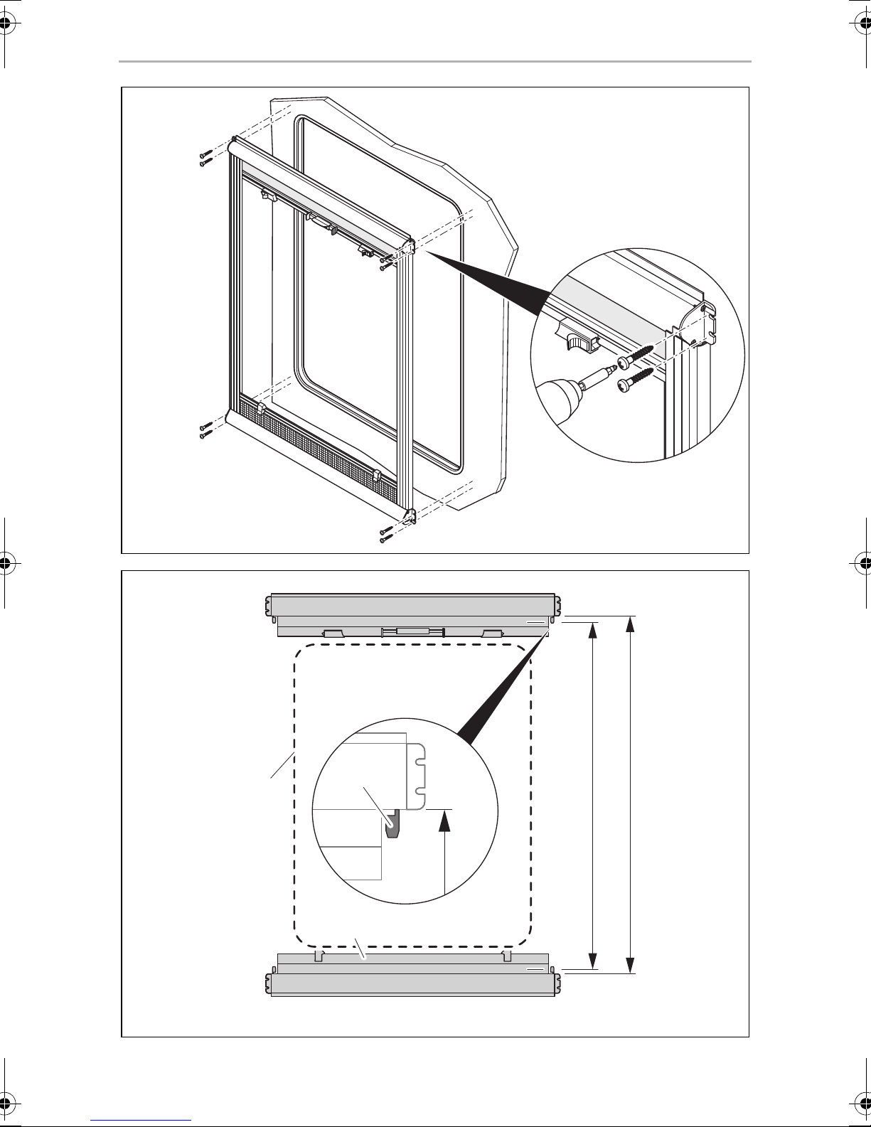
➤ Fix the roller blind cassettes using the supplied screws to the wall of the vehicle
(fig. 6, page 6).
3.1 Shortening the guide rails
If the guide rails are too long, they can be shortened as follows:
Measure the length of the guide rails (fig. 7, page 6)
➤ Determine the length of the guide rails by holding the roller blind cassettes
against the upper and lower edge of the window (2).
The handle strip (1) should not project into the clear height F of the window cut-
out.
➤ Measure the dimension B between the surface stops of the mortises and
tenons (3).
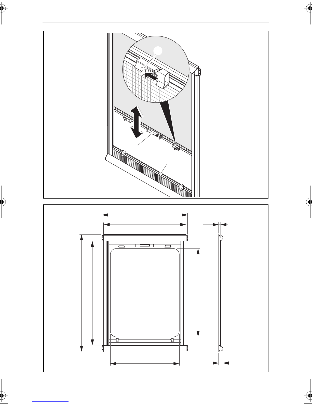
Cutting the guide rails to length (fig. 8, page 7)
NOTICE!
Saw both guide rails off square and to equal lengths.
A
➤ Saw the same end of both guide rails (with the same distance to the slots) to the
length of dimension B.
➤ Use the waste pieces to measure the length B1 from the slots to the end of the
pieces.
➤ Deburr both guide rails.
➤ Use a 2-mm drill to pre-drill new slots at the distance of B1 from the new end of
both guide rails.
➤ Make the pre-drilled holes into slots (1).
11
Page 12
EN
Using the blind Dometic
4 Using the blind
4.1 Closing the blind
NOTICE! Risk of damage due to a build-up of heat between the
A
➤ Connect the handle strip of the blackout roller blind (fig. 9 1, page 7) with the
handle strip of the flyscreen (fig. 9 2, page 7).
To do so, press the push buttons (fig. 9 3, page 7) together and draw both
handle strips together.
➤ Lock the flyscreen (fig. 0 2, page 7) into place on the blackout roller blind
(fig. 0 1, page 7).
roller blind and the window.
In strong sunlight, only close the blackout roller blind two thirds of the
way.
➤ Press the push buttons (fig. 0 3, page 7) and push the roller blinds that are now
locked together into the desired position.
➤ Release the push buttons and latch the roller blinds into the next catch point.
There are catch points at the respective end positions of the roller blinds and in
the centre of the guide rails.
4.2 Opening the blind
➤ Guide the roller blind (fig. a 2, page 8) downwards with your hand.
➤ Latch the roller blind into the lowest position, so that the flyscreen is rolled up in
its cassette.
➤ Separate the roller blinds by pressing the locking mechanism (fig. a 3, page 8).
Do not let the blackout roller blind spring back.
➤ Latch the blackout roller blind (fig. a 1, page 8) into the desired catch point.
12
Page 13

EN
Dometic Troubleshooting
5 Troubleshooting
The flyscreen or blackout roller blind cannot be moved.
➤ Check the guide rails for dirt.
➤ Clean the guide rails if necessary.
The tension of the spring drive is insufficient
➤ Re-tension the spring drive or replace it.
6 Cleaning and maintenance
NOTICE!
A
Do not use sharp or hard objects or cleaning agents for cleaning as these
may damage the product.
➤ Occasionally clean the product with a damp cloth.
➤ Spray the sliding surfaces of the guide rails periodically with small amounts of
silicone spray to achieve the smoothest possible sliding of the handle strips in the
guide rails.
➤ To prevent material fatigue, do not keep the blind closed for long periods of
time.
➤ If the vehicle is stationary for long periods of time, engage the blackout roller
blind in the highest catch point and the flyscreen in the lowest catch point. This is
to prevent the formation of mildew.
7Warranty
The statutory warranty period applies. If the product is defective, please contact your
retailer or the manufacturer's branch in your country (see the back of the instruction
manual for the addresses).
For repair and guarantee processing, please include the following documents when
you send in the device:
• A copy of the receipt with purchasing date
• A reason for the claim or description of the fault
13
Page 14

EN
Technical data Dometic
8 Technical data
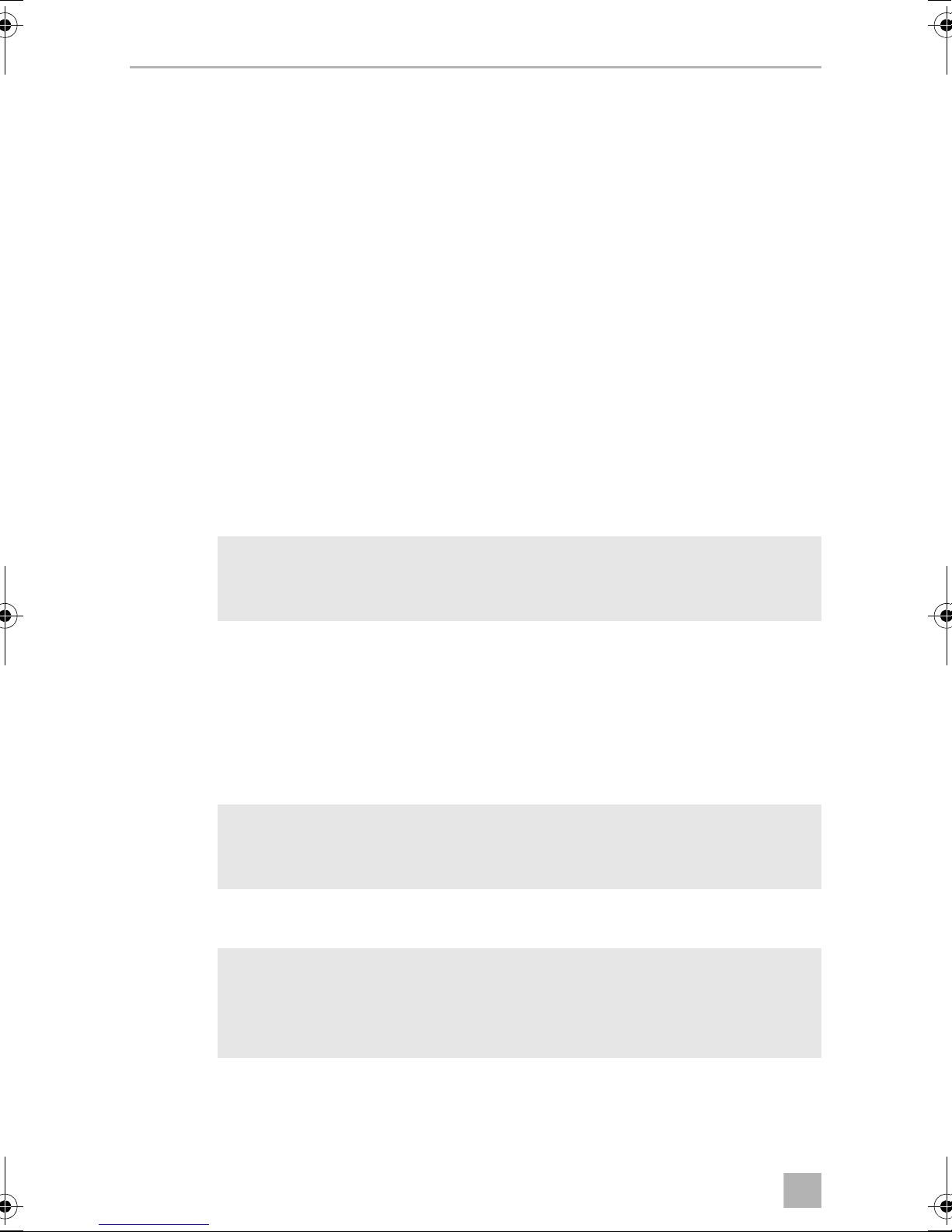
You will find the dimensional drawing in fig. b, page 8:
Ref. no.
9104100052
9104100065
9104100053
9104100066
9104100054
9104100067
9104100055
9104100068
9104100056
9104100069
9104100057
9104100070
9104100058
9104100071
9104100059
9104100072
Order size
Width A x height B
630 x 700 mm 658 mm 790 mm 580 mm 650 mm 1.30 kg
680 x 700 mm 708 mm 790 mm 630 mm 650 mm 1.35 kg
730 x 700 mm 758 mm 790 mm 680 mm 650 mm 1.41 kg
780 x 700 mm 808 mm 790 mm 730 mm 650 mm 1.47 kg
830 x 700 mm 858 mm 790 mm 780 mm 650 mm 1.53 kg
930 x 700 mm 958 mm 790 mm 880 mm 650 mm 1.65 kg
1030 x 700 mm 1058 mm 790 mm 980 mm 650 mm 1.77 kg
1130 x 700 mm 1158 mm 790 mm 1080 mm 650 mm 1.89 kg
C D E F Wei ght
9104100060
9104100073
9104100061
9104100074
9104100062
9104100075
9104100063
9104100076
9104100064
9104100077
1230 x 700 mm 1258 mm 790 mm 1180 mm 650 mm 2.00 kg
1330 x 750 mm 1358 mm 840 mm 1280 mm 700 mm 2.15 kg
1430 x 750 mm 1458 mm 840 mm 1380 mm 700 mm 2.27 kg
1480 x 750 mm 1508 mm 840 mm 1430 mm 700 mm 2.33 kg
1530 x 750 mm 1558 mm 840 mm 1480 mm 700 mm 2.39 kg
Key
C: Total width
D: Total height
E: Width of the window cut-out
F: Clear height of the window cut-out
14
Page 15
DE
Dometic Lieferumfang
Bitte lesen Sie diese Anleitung vor Einbau und Inbetriebnahme sorgfältig
durch und bewahren Sie sie auf. Geben Sie sie im Falle einer Weitergabe
des Produktes an den Nutzer weiter.
Inhalt
1 Lieferumfang . . . . . . . . . . . . . . . . . . . . . . . . . . . . . . . . . . . . . . . . . . . . . . . . . .15
2 Bestimmungsgemäßer Gebrauch . . . . . . . . . . . . . . . . . . . . . . . . . . . . . . . . .15
3 Rollo montieren. . . . . . . . . . . . . . . . . . . . . . . . . . . . . . . . . . . . . . . . . . . . . . . .16
4 Rollo benutzen . . . . . . . . . . . . . . . . . . . . . . . . . . . . . . . . . . . . . . . . . . . . . . . .18
5 Störungsbeseitigung . . . . . . . . . . . . . . . . . . . . . . . . . . . . . . . . . . . . . . . . . . .19
6 Reinigung und Pflege . . . . . . . . . . . . . . . . . . . . . . . . . . . . . . . . . . . . . . . . . . .19
7 Gewährleistung. . . . . . . . . . . . . . . . . . . . . . . . . . . . . . . . . . . . . . . . . . . . . . . 20
8 Technische Daten . . . . . . . . . . . . . . . . . . . . . . . . . . . . . . . . . . . . . . . . . . . . . .21
1 Lieferumfang
Pos. in
Abb. 1, Seite 3
1 1 Rollokassette Verdunkelungsrollo
2 1 Rollokassette Insektenschutzgitter
3 2 Führungsschienen
4 12 Befestigungsschrauben
Anzahl Beschreibung
2 Bestimmungsgemäßer Gebrauch
Das Mini-Doppelkassettenrollo ist geeignet für Fenster in Wohnmobilen oder Wohnwagen. Es besitzt ein Fliegenschutzrollo und ein Verdunkelungsrollo.
15
Page 16
DE
Rollo montieren Dometic
3 Rollo montieren
➤ Prüfen Sie vor der Montage, ob genügend Platz für das Rollo vorhanden ist.
Sie können die Führungsschienen bei Bedarf kürzen (siehe Kapitel „Führungsschienen kürzen“ auf Seite 17).
Rollokassetten zusammen stecken (Abb. 2, Seite 4)
➤ Richten Sie die Einzelteile wie dargestellt aus.
Sie müssen die Enden mit dem kurzen Abstand zu den Langlöchern (4) auf die
Zapfen des Verdunkelungsrollos ausrichten.
➤ Stecken Sie die beiden Rollokassetten (1) und (2) und die beiden Führungs-
schienen (3) zu einem geschlossenen Rahmen zusammen:
– Fädeln Sie die Griffleisten (5) der Rollos in die Führungsschienen ein.
– Stecken Sie die Zapfen (6) in die Rastlöcher (7).
Rollo befestigen
HINWEIS
I
➤ Richten Sie den Rahmen wie folgt am Fenster aus (Abb. 3, Seite 5):
– Sowohl links und rechts als auch oben und unten muss der Abstand zum
– Die Rollokassetten müssen parallel zum oberen und unteren Fensterrand ver-
– Die Führungsschienen müssen rechtwinkelig zu den Rollokassetten stehen.
I
➤ Zeichnen Sie die Befestigungsbohrungen in den Lagerdeckeln an der Wand an
(Abb. 4, Seite 5).
Sie können sowohl die Verdunkelung oben und den Insektenschutz
unten am Rollo montieren, als auch umgekehrt.
Gummiprofil des Fensters gleich sein.
laufen.
HINWEIS
Wenn die Führungsschienen zu lang sind, können Sie diese kürzen
(siehe Kapitel „Führungsschienen kürzen“ auf Seite 17).
ACHTUNG!
A
16
• Wenn die mitgelieferten Schrauben in der Wand keinen Halt finden,
müssen Sie abhängig von der Wandkonstruktion geeignete Dübel
verwenden.
• Achten Sie darauf, dass Sie die Wand nicht durchbohren.
Page 17

DE
Dometic Rollo montieren
➤ Bohren Sie die Befestigungsbohrungen mit einem Bohrer von Ø 2 mm vor
(Abb. 5, Seite 5).
➤ Befestigen Sie die Rollokassetten mit den beiliegenden Schrauben an der
Fahrzeugwand (Abb. 6, Seite 6).
3.1 Führungsschienen kürzen
Wenn die Führungsschienen zu lang sind, können Sie diese wie folgt kürzen:
Länge der Führungsschienen messen (Abb. 7, Seite 6)
➤ Bestimmen Sie die Länge der Führungsschienen, indem Sie die Rollokassetten an
der oberen und unteren Kante des Fensters (2) anlegen.
Die Griffleisten (1) sollten nicht in die lichte Höhe F des Fensterausschnitts
hineinragen.
➤ Messen Sie das Maß B zwischen den Anschlagflächen der Zapfen (3).
Führungsschienen ablängen (Abb. 8, Seite 7)
ACHTUNG!
Sägen Sie beide Führungsschienen gleich lang und rechtwinkelig ab.
A
➤ Sägen Sie beide Führungsschienen am gleichen Ende (gleicher Abstand zu den
Langlöchern) auf das Maß B ab.
➤ Messen Sie an den Abfallstücken den Abstand B1 der Langlöcher zum Ende.
➤ Entgraten Sie die beiden Führungsschienen.
➤ Bohren Sie am neuen Ende der beiden Führungsschienen mit einem 2-mm-
Bohrer neue Langlöcher im Abstand B1 vor.
➤ Fertigen Sie die Langlöcher (1) an.
17
Page 18

DE
Rollo benutzen Dometic
4 Rollo benutzen
4.1 Rollo schließen
ACHTUNG! Beschädigungsgefahr durch Hitzestau zwischen
A
➤ Verbinden Sie der Griffleiste des Verdunkelungsrollos (Abb. 9 1, Seite 7) mit
der Griffleiste des Insektenschutzrollos (Abb. 9 2, Seite 7).
Drücken Sie hierzu die Drucktasten (Abb. 9 3, Seite 7) zusammen, und führen
Sie die beiden Griffleisten zueinander.
➤ Lassen Sie das Insektenschutzrollos (Abb. 0 2, Seite 7) am Verdunkelungs-
rollos (Abb. 0 1, Seite 7) einrasten.
Rollo und Glasscheibe!
Bei starker Sonneneinstrahlung dürfen Sie das Verdunkelungsrollo nur
zu zwei Dritteln schließen.
➤ Drücken Sie die Drucktasten (Abb. 0 3, Seite 7) und schieben Sie die
zusammengerasteten Rollos in die gewünschte Position.
➤ Lassen Sie die Drucktasten los und rasten Sie die Rollos in der nächsten Rastung
ein.
Rastungen sind jeweils in den Endlagen der Rollos und in der Mitte der Füh-
rungsschienen vorhanden.
4.2 Rollo öffnen
➤ Führen Sie das Rollo (Abb. a 2, Seite 8) mit der Hand nach unten.
➤ Rasten Sie das Rollo in der untersten Stellung ein, so dass das Insektenschutzrollo
in seiner Kassette aufgerollt ist.
➤ Trennen Sie die Rollos, indem Sie die Verriegelungen (Abb. a 3, Seite 8)
drücken.
Lassen Sie das Verdunkelungsrollo nicht zurückschnellen.
➤ Rasten Sie das Verdunkelungsrollo (Abb. a 1, Seite 8) in der gewünschten
Rastung ein.
18
Page 19
DE
Dometic Störungsbeseitigung
5 Störungsbeseitigung
Das Insektenschutz- oder Verdunkelungsrollo lassen sich nicht
verschieben
➤ Prüfen Sie die Führungsschienen auf Verschmutzungen.
➤ Reinigen Sie gegebenenfalls die Führungsschienen.
Die Spannung des Federmotors ist zu gering
➤ Spannen Sie den Federmotor nach, oder tauschen Sie ihn aus.
6 Reinigung und Pflege
ACHTUNG!
A
Keine scharfen oder harten Gegenstände oder Reinigungsmittel zur
Reinigung verwenden, da dies zu einer Beschädigung des Produktes
führen kann.
➤ Reinigen Sie das Produkt gelegentlich mit einem feuchten Tuch.
➤ Sprühen Sie die Führungsschienen an den Gleitflächen in regelmäßigen
Abständen mit Silikonspray in geringer Dosis ein, um ein möglichst leichtes
Gleiten der Griffleisten in den Führungsschienen zu erreichen.
➤ Halten Sie das Rollo nicht über einen längeren Zeitraum geschlossen, um
Materialermüdung zu vermeiden.
➤ Bei längerem Stillstand des Fahrzeuges rasten Sie das Verdunkelungsrollo in der
obersten Rastung und das Insektenschutzrollo in der untersten Rastung ein. So
beugen Sie Schimmelbildung vor.
19
Page 20
DE
Gewährleistung Dometic
7Gewährleistung
Es gilt die gesetzliche Gewährleistungsfrist. Sollte das Produkt defekt sein, wenden
Sie sich bitte an Ihren Fachhändler oder an die Niederlassung des Herstellers in
Ihrem Land (Adressen siehe Rückseite der Anleitung).
Zur Reparatur- bzw. Gewährleistungsbearbeitung müssen Sie folgende Unterlagen
mitschicken:
• eine Kopie der Rechnung mit Kaufdatum,
• einen Reklamationsgrund oder eine Fehlerbeschreibung.
20
Page 21
DE
Dometic Technische Daten
8 Technische Daten
Die Maßzeichnung finden Sie in Abb. b, Seite 8:
Art.-Nr.
9104100052
9104100065
9104100053
9104100066
9104100054
9104100067
9104100055
9104100068
9104100056
9104100069
9104100057
9104100070
9104100058
9104100071
9104100059
9104100072
Bestellmaß
Breite A x Höhe B
630 x 700 mm 658 mm 790 mm 580 mm 650 mm 1,30 kg
680 x 700 mm 708 mm 790 mm 630 mm 650 mm 1,35 kg
730 x 700 mm 758 mm 790 mm 680 mm 650 mm 1,41 kg
780 x 700 mm 808 mm 790 mm 730 mm 650 mm 1,47 kg
830 x 700 mm 858 mm 790 mm 780 mm 650 mm 1,53 kg
930 x 700 mm 958 mm 790 mm 880 mm 650 mm 1,65 kg
1030 x 700 mm 1058 mm 790 mm 980 mm 650 mm 1,77 kg
1130 x 700 mm 1158 mm 790 mm 1080 mm 650 mm 1,89 kg
C D E F Gewicht
9104100060
9104100073
9104100061
9104100074
9104100062
9104100075
9104100063
9104100076
9104100064
9104100077
1230 x 700 mm 1258 mm 790 mm 1180 mm 650 mm 2,00 kg
1330 x 750 mm 1358 mm 840 mm 1280 mm 700 mm 2,15 kg
1430 x 750 mm 1458 mm 840 mm 1380 mm 700 mm 2,27 kg
1480 x 750 mm 1508 mm 840 mm 1430 mm 700 mm 2,33 kg
1530 x 750 mm 1558 mm 840 mm 1480 mm 700 mm 2,39 kg
Legende
C: Gesamtbreite
D: Gesamthöhe
E: Breite Fensterausschnitt
F: Lichte Höhe Fensterausschnitt
21
Page 22
FR
Pièces fournies Dometic
Veuillez lire attentivement cette notice avant le montage et la mise en
service. Veuillez ensuite la conserver. En cas de passer le produit, veuillez
le transmettre au nouvel acquéreur.
Sommaire
1 Pièces fournies . . . . . . . . . . . . . . . . . . . . . . . . . . . . . . . . . . . . . . . . . . . . . . . 22
2 Usage conforme . . . . . . . . . . . . . . . . . . . . . . . . . . . . . . . . . . . . . . . . . . . . . . 22
3 Montage du store . . . . . . . . . . . . . . . . . . . . . . . . . . . . . . . . . . . . . . . . . . . . . 23
4 Utilisation du store . . . . . . . . . . . . . . . . . . . . . . . . . . . . . . . . . . . . . . . . . . . . 25
5 Guide de dépannage . . . . . . . . . . . . . . . . . . . . . . . . . . . . . . . . . . . . . . . . . . 26
6 Entretien et nettoyage . . . . . . . . . . . . . . . . . . . . . . . . . . . . . . . . . . . . . . . . . 26
7 Garantie. . . . . . . . . . . . . . . . . . . . . . . . . . . . . . . . . . . . . . . . . . . . . . . . . . . . . 26
8 Caractéristiques techniques . . . . . . . . . . . . . . . . . . . . . . . . . . . . . . . . . . . . . 27
1Pièces fournies
Pos. dans
fig. 1, page 3
1 1 Cassette de store occultant
2 1 Cassette de store moustiquaire
3 2 Glissières latérales
4 12 Vis de fixation
Nombre Description
2Usage conforme
Le mini store double à cassette est conçu pour les caravanes et les camping-cars. Il
est équipé d’une moustiquaire et d’un store occultant.
22
Page 23
FR
Dometic Montage du store
3 Montage du store
➤ Avant le montage, vérifiez que vous disposez de suffisamment de place pour le
store.
Vous pouvez raccourcir les glissières latérales, si besoin (voir chapitre
« Raccourcissement des glissières latérales », page 24).
Assemblage des cassettes de store (fig. 2, page 4)
➤ Orientez les pièces comme indiqué sur l’illustration.
Vous devez positionner les extrémités possédant le plus petit espace entre les
trous oblongs (4) et le rebord face aux tenons du store occultant.
➤ Assemblez les deux cassettes de store (1) et (2) et les deux glissières latérales (3)
afin d’obtenir un cadre fermé.
– Faites passer les poignées (5) des stores dans les glissières latérales.
– Introduisez les tenons (6) dans les trous à encoches (7).
Fixation du store
REMARQUE
I
➤ Positionnez le cadre contre la fenêtre en respectant les consignes suivantes
(fig. 3, page 5) :
– Veillez à ce que l’espace entre le cadre et le profil en caoutchouc de la fenêtre
– Les cassettes de store doivent être parallèles aux bords supérieur et inférieur
– Les glissières latérales doivent former un angle droit avec les cassettes de
I
Vous pouvez monter le store occultant en haut et la moustiquaire en bas
ou inversement.
soit le même à droite, à gauche, en haut et en bas.
de la fenêtre.
store.
REMARQUE
Si les glissières latérales sont trop longues, vous pouvez les raccourcir
(voir chapitre « Raccourcissement des glissières latérales », page 24).
➤ Marquez l’emplacement des alésages de fixation sur les chapeaux de palier au
mur (fig. 4, page 5).
23
Page 24
FR
Montage du store Dometic
AVIS !
A
➤ Effectuez un préperçage des alésages de fixation à l’aide d’une mèche de 2 mm
de diamètre (fig. 5, page 5).
➤ Fixez les cassettes de store à la paroi du véhicule à l’aide des vis fournies (fig. 6,
page 6).
• Si les vis fournies ne peuvent pas être fixées au mur, vous devez
utiliser des chevilles adaptées à la nature du mur.
• Veillez à ne pas perforer le mur.
3.1 Raccourcissement des glissières latérales
Si les glissières latérales sont trop longues, vous pouvez les raccourcir comme suit :
Mesure de la longueur des glissières latérales (fig. 7, page 6)
➤ Déterminez la longueur que devront avoir les glissières latérales en appliquant
les cassettes de store contre le bord supérieur et le bord inférieur de la fenêtre
(2).
Les poignées (1) ne doivent pas dépasser la hauteur intérieure F de la découpe
de fenêtre.
➤ Mesurez ensuite la distance B qui sépare les surfaces de butée des tenons (3).
Coupe à longueur des glissières latérales (fig. 8, page 7)
AVIS !
Sciez les deux glissières latérales à la même longueur et à angle droit.
A
➤ Sciez les deux glissières latérales au même niveau (même espace entre l’extré-
mité et les trous oblongs) de sorte qu’elles soient de longueur B.
➤ Mesurez sur les morceaux sciés la distance B1 séparant les trous oblongs de
l’extrémité.
➤ Ébavurez les deux glissières latérales.
➤ Sur les deux glissières latérales, effectuez un préperçage de nouveaux trous
oblongs situés à la distance B1 de l’extrémité raccourcie à l’aide d’une mèche de
2mm.
➤ Procédez au perçage des trous oblongs (1).
24
Page 25
FR
Dometic Utilisation du store
4 Utilisation du store
4.1 Fermeture du store
AVIS ! Risque d’endommagement en raison de l’accumulation
A
➤ Fixez la poignée du store occultant (fig. 9 1, page 7) à la poignée de la
moustiquaire (fig. 9 2, page 7).
Appuyez pour cela simultanément sur les deux côtés de la fixation (fig. 9 3,
page 7) et rapprochez les poignées l’une de l’autre.
➤ Faites s’encliqueter la moustiquaire (fig. 0 2, page 7) et le store occultant
(fig. 0 1, page 7).
de chaleur entre le store et la vitre
En cas de fort rayonnement solaire, vous ne devez fermer le store
occultant qu’aux deux tiers.
➤ Appuyez sur les deux côtés de la fixation (fig. 0 3, page 7) et manœuvrez les
stores simultanément pour les régler sur la position souhaitée.
➤ Relâchez la fixation et encliquetez les stores au cran suivant.
Il existe deux crans à chaque extrémité des stores et un au centre des glissières
latérales.
4.2 Ouverture du store
➤ Tirez le store (fig. a 2, page 8) manuellement vers le bas.
➤ Mettez le store dans la position la plus basse de manière à ce que la moustiquaire
soit complètement enroulée dans sa cassette.
➤ Séparez les stores en appuyant sur les dispositifs de verrouillage (fig. a 3,
page 8).
Ne laissez pas le store occultant se rabattre seul.
➤ Réglez le store occultant (fig. a 1, page 8) en le faisant s’encliqueter au cran
souhaité.
25
Page 26
FR
Guide de dépannage Dometic
5 Guide de dépannage
La moustiquaire ou le store occultant ne coulissent plus.
➤ Contrôlez l’état de propreté des glissières latérales.
➤ Nettoyez les glissières latérales, le cas échéant.
La tension du moteur à ressort est trop faible.
➤ Retendez le moteur à ressort ou changez-le.
6 Entretien et nettoyage
AVIS !
A
N’utilisez aucun objet coupant ou dur, ni de détergents pour le
nettoyage. Cela pourrait endommager le produit.
➤ Nettoyez le produit avec un tissu humide.
➤ Vaporisez à intervalles réguliers une faible dose de spray au silicone sur les
surfaces de glissement des glissières latérales afin que les poignées glissent aussi
facilement que possible dans les glissières latérales.
➤ Ne laissez pas le store fermé pendant une période prolongée pour éviter que le
matériau ne s’use.
➤ En cas d’immobilisation prolongée du véhicule, encliquetez le store occultant au
cran le plus haut et la moustiquaire au cran le plus bas. Vous éviterez ainsi la
formation de moisissures.
7 Garantie
Le délai légal de garantie s'applique. Si le produit s'avérait défectueux, veuillez vous
adresser à la filiale du fabricant située dans votre pays (voir adresses au verso du
présent manuel) ou à votre revendeur spécialisé.
Veuillez y joindre les documents suivants pour la gestion des réparations et de la
garantie :
• une copie de la facture avec la date d'achat,
• le motif de la réclamation ou une description du dysfonctionnement.
26
Page 27

FR
Dometic Caractéristiques techniques
8 Caractéristiques techniques
Vous trouverez les schémas cotés dans fig. b, page 8 :
Dimensions
N° de produit
Largeur A x
Hauteur B
C D E F Poids
9104100052
9104100065
9104100053
9104100066
9104100054
9104100067
9104100055
9104100068
9104100056
9104100069
9104100057
9104100070
9104100058
9104100071
9104100059
9104100072
9104100060
9104100073
630 x 700 mm 658 mm 790 mm 580 mm 650 mm 1,30 kg
680 x 700 mm 708 mm 790 mm 630 mm 650 mm 1,35 kg
730 x 700 mm 758 mm 790 mm 680 mm 650 mm 1,41 kg
780 x 700 mm 808 mm 790 mm 730 mm 650 mm 1,47 kg
830 x 700 mm 858 mm 790 mm 780 mm 650 mm 1,53 kg
930 x 700 mm 958 mm 790 mm 880 mm 650 mm 1,65 kg
1 030 x 700 mm 1 058 mm 790 mm 980 mm 650 mm 1,77 kg
1 130 x 700 mm 1 158 mm 790 mm 1 080 mm 650 mm 1,89 kg
1 230 x 700 mm 1 258 mm 790 mm 1 180 mm 650 mm 2,00 kg
9104100061
9104100074
9104100062
9104100075
9104100063
9104100076
9104100064
9104100077
1 330 x 750 mm 1 358 mm 840 mm 1 280 mm 700 mm 2,15 kg
1 430 x 750 mm 1 458 mm 840 mm 1 380 mm 700 mm 2,27 kg
1 480 x 750 mm 1 508 mm 840 mm 1 430 mm 700 mm 2,33 kg
1 530 x 750 mm 1 558 mm 840 mm 1 480 mm 700 mm 2,39 kg
Légende
C : largeur totale
D : hauteur totale
E : largeur de la découpe de fenêtre
F : hauteur intérieure de la découpe de fenêtre
27
Page 28
ES
Volumen de entrega Dometic
Lea detenidamente estas instrucciones antes de llevar a cabo la instalación
y puesta en funcionamiento, y consérvelas en un lugar seguro. En caso de
vender o entregar el producto a otra persona, entregue también estas
instrucciones.
Índice
1 Volumen de entrega . . . . . . . . . . . . . . . . . . . . . . . . . . . . . . . . . . . . . . . . . . . 28
2 Uso adecuado. . . . . . . . . . . . . . . . . . . . . . . . . . . . . . . . . . . . . . . . . . . . . . . . 28
3 Montar el estor . . . . . . . . . . . . . . . . . . . . . . . . . . . . . . . . . . . . . . . . . . . . . . . 29
4 Utilizar el estor. . . . . . . . . . . . . . . . . . . . . . . . . . . . . . . . . . . . . . . . . . . . . . . . .31
5 Solución de averías . . . . . . . . . . . . . . . . . . . . . . . . . . . . . . . . . . . . . . . . . . . . 32
6 Limpieza y mantenimiento . . . . . . . . . . . . . . . . . . . . . . . . . . . . . . . . . . . . . . 32
7 Garantía legal . . . . . . . . . . . . . . . . . . . . . . . . . . . . . . . . . . . . . . . . . . . . . . . . 32
8 Datos técnicos. . . . . . . . . . . . . . . . . . . . . . . . . . . . . . . . . . . . . . . . . . . . . . . . 33
1 Volumen de entrega
Pos. en
fig. 1, página 3
1 1 Cajón de estor de oscurecimiento
2 1 Cajón de estor de mosquitera
3 2 Carriles guía
4 12 Tornillos de fijación
To t a l Descripción
2Uso adecuado
El estor de cajón doble mini es adecuado para las ventanas de caravanas y autocaravanas. Dispone de un estor de mosquitera y de un estor de oscurecimiento.
28
Page 29
ES
Dometic Montar el estor
3 Montar el estor
➤ Antes del montaje, compruebe si hay disponible espacio suficiente para el estor.
Si fuera necesario, los carriles guía se pueden acortar (véase capítulo “Acortar los
carriles guía” en la página 30).
Encastre los cajones de estor (fig. 2, página 4)
➤ Alinee cada una de las piezas según se muestra.
Debe alinear los extremos con la menor distancia a los orificios alargados (4) en
los quicios del estor de oscurecimiento.
➤ Encastre los dos cajones de estor (1) y (2) y ambos carriles guías (3) para que
formen un marco cerrado:
– Coloque los perfiles en C (5) del estor en los carriles guía.
– Inserte los quicios (6) en los orificios de encastre (7).
Fijar el estor
NOTA
I
➤ Alinee el marco con la ventana según se indica a continuación (fig. 3, página 5):
– La distancia con respecto al perfil de goma de la ventana debe ser la misma
– Los cajones de estor deben quedar paralelos al marco de ventana superior e
– Los carriles guía deben quedar perpendiculares con respecto a las cajas de
I
➤ Marque en la pared los orificios de fijación situados en las tapas (fig. 4,
página 5).
Usted tiene la posibilidad de montar el oscurecimiento en la parte de
arriba del estor y la mosquitera en la parte de abajo o viceversa.
tanto a la izquierda y a la derecha como arriba y abajo.
inferior.
los estores.
NOTA
Si son demasiado largos, los carriles guía se pueden acortar (véase
capítulo “Acortar los carriles guía” en la página 30).
¡AVISO!
A
• Si los tornillos suministrados no pueden fijarse a la pared, deberá
utilizar tacos adecuados en función de cómo está construida dicha
pared.
• Preste atención a no taladrar la pared.
29
Page 30
ES
Montar el estor Dometic
➤ Perfore los orificios de fijación con un taladro de Ø 2 mm (fig. 5, página 5).
➤ Fije el cajón de estor a la pared del vehículo con los tornillos suministrados
(fig. 6, página 6).
3.1 Acortar los carriles guía
Si son demasiado largos, los carriles guía se pueden acortar de la siguiente manera:
Mida el largo de los carriles guía (fig. 7, página 6)
➤ Para determinar el largo de los carriles guía, sitúe el cajón de estor en la esquina
superior e inferior de la ventana (2).
Los perfiles en C (1) no deben sobresalir por encima de la altura libre F del hueco
de la ventana.
➤ Determine la medida B entre las superficies de tope de los quicios (3).
Tronzar los carriles guía (fig. 8, página 7)
¡AVISO!
A
➤ Sierre ambos carriles guía por el mismo extremo (con la misma distancia a los
orificios alargados) a la medida B.
➤ Mida en las piezas restantes la distancia B1 de los orificios alargados con respecto
al extremo.
➤ Desbarbe ambos carriles guía.
➤ Perfore con un taladro de 2 mm nuevos orificios alargados conformes a la
distancia B1 en los nuevos extremos de ambos carriles guía.
➤ Produzca ambos orificios alargados (1).
Sierre ambos carriles guía para que queden con la misma longitud y en
ángulo recto.
30
Page 31

ES
Dometic Utilizar el estor
4 Utilizar el estor
4.1 Cerrar el estor
¡AVISO! Peligro de que se produzcan daños debido a la
A
➤ Una el perfil en C del estor de oscurecimiento (fig. 9 1, página 7) con el perfil
en C del estor de mosquitera (fig. 9 2, página 7).
Apriete para ello los pulsadores (fig. 9 3, página 7) y una ambos perfiles en C.
➤ Encastre el estor de mosquitera (fig. 0 2, página 7) en el estor de oscureci-
miento (fig. 0 1, página 7).
➤ Apriete los pulsadores (fig. 0 3, página 7) y deslice los estores encastrados
entre sí hasta la posición deseada.
acumulación de calor entre persiana y cristal.
Si la radiación solar es muy intensa, la persiana de oscurecimiento solo
debe bajarse dos tercios.
➤ Suelte los pulsadores y enganche los estores en el próximo encastre.
Hay encastres disponibles en los extremos de los estores y en el centro de los
carriles guía.
4.2 Abrir el estor
➤ Deslice el estor (fig. a 2, página 8) con la mano hacia abajo.
➤ Encaje el estor en la posición más baja de manera que el estor de mosquitera
quede enrollado en su caja.
➤ Separe los estores presionando el bloqueo (fig. a 3, página 8).
No permita que el estor de oscurecimiento se cierre de golpe.
➤ Encaje el estor de oscurecimiento (fig. a 1, página 8) en el encastre deseado.
31
Page 32

ES
Solución de averías Dometic
5 Solución de averías
La persiana de oscurecimiento o la persiana mosquitera no pueden
cerrarse.
➤ Compruebe si hay suciedades en los carriles guía.
➤ En caso necesario limpie los carriles guía.
La tensión del motor de resorte es demasiado limitada.
➤ Aplique más tensión al motor de resorte o reemplácelo.
6 Limpieza y mantenimiento
¡AVISO!
A
No utilice ningún objeto o producto de limpieza corrosivo o duro en la
limpieza, ya que podría dañar el producto.
➤ Limpie de vez en cuando el producto con un paño húmedo.
➤ Pulverice a intervalos regulares las superficies de deslizamiento de los carriles
guía con spray de silicona en pequeñas dosis para alcanzar una suave deslizamiento de los perfiles en C en los carriles guía.
➤ No deje el estor cerrado durante demasiado tiempo para evitar que los
materiales se deterioren.
➤ En caso de parada prolongada del vehículo, encaje el estor de oscurecimiento
en el encastre superior y el estor de mosquitera en el encastre inferior. De este
modo se evita la formación de moho.
7 Garantía legal
Rige el plazo de garantía legal. Si el producto presenta algún defecto, diríjase a su
establecimiento especializado o a la sucursal del fabricante de su país (ver
direcciones en el dorso de estas instrucciones).
Para la tramitación de la reparación y de la garantía debe enviar también los
siguientes documentos:
• una copia de la factura con fecha de compra,
• el motivo de la reclamación o una descripción de la avería.
32
Page 33

ES
Dometic Datos técnicos
8 Datos técnicos
Encontrará el esquema de dimensiones en la fig. b, página 8:
N.° de art.
9104100052
9104100065
9104100053
9104100066
9104100054
9104100067
9104100055
9104100068
9104100056
9104100069
9104100057
9104100070
9104100058
9104100071
9104100059
9104100072
Medidas de pedido
Ancho A x altura B
630 x 700 mm 658 mm 790 mm 580 mm 650 mm 1,30 kg
680 x 700 mm 708 mm 790 mm 630 mm 650 mm 1,35 kg
730 x 700 mm 758 mm 790 mm 680 mm 650 mm 1,41 kg
780 x 700 mm 808 mm 790 mm 730 mm 650 mm 1,47 kg
830 x 700 mm 858 mm 790 mm 780 mm 650 mm 1,53 kg
930 x 700 mm 958 mm 790 mm 880 mm 650 mm 1,65 kg
1030 x 700 mm 1058 mm 790 mm 980 mm 650 mm 1,77 kg
1130 x 700 mm 1158 mm 790 mm 1080 mm 650 mm 1,89 kg
C D E F Peso
9104100060
9104100073
9104100061
9104100074
9104100062
9104100075
9104100063
9104100076
9104100064
9104100077
1230 x 700 mm 1258 mm 790 mm 1180 mm 650 mm 2,00 kg
1330 x 750 mm 1358 mm 840 mm 1280 mm 700 mm 2,15 kg
1430 x 750 mm 1458 mm 840 mm 1380 mm 700 mm 2,27 kg
1480 x 750 mm 1508 mm 840 mm 1430 mm 700 mm 2,33 kg
1530 x 750 mm 1558 mm 840 mm 1480 mm 700 mm 2,39 kg
Leyenda
C: Ancho total
D: Altura total
E: Ancho del hueco de la ventana
F: Altura libre del hueco de la ventana
33
Page 34

PT
Material fornecido Dometic
Por favor, leia atentamente este manual antes da montagem e colocação
em funcionamento do aparelho e guarde-o em local seguro. Em caso de
transmissão do produto, entregue o manual ao novo utilizador.
Índice
1 Material fornecido. . . . . . . . . . . . . . . . . . . . . . . . . . . . . . . . . . . . . . . . . . . . . 34
2 Utilização adequada . . . . . . . . . . . . . . . . . . . . . . . . . . . . . . . . . . . . . . . . . . . 34
3 Montar a persiana . . . . . . . . . . . . . . . . . . . . . . . . . . . . . . . . . . . . . . . . . . . . . 35
4 Utilizar a persiana . . . . . . . . . . . . . . . . . . . . . . . . . . . . . . . . . . . . . . . . . . . . . 37
5 Resolução de falhas. . . . . . . . . . . . . . . . . . . . . . . . . . . . . . . . . . . . . . . . . . . . 38
6 Limpeza e manutenção. . . . . . . . . . . . . . . . . . . . . . . . . . . . . . . . . . . . . . . . . 38
7 Garantia . . . . . . . . . . . . . . . . . . . . . . . . . . . . . . . . . . . . . . . . . . . . . . . . . . . . . 38
8 Dados técnicos . . . . . . . . . . . . . . . . . . . . . . . . . . . . . . . . . . . . . . . . . . . . . . . 39
1 Material fornecido
Pos. na
fig. 1, página 3
1 1 Persiana de escurecimento
2 1 Persiana com rede contra insetos
3 2 Calhas de guia
4 12 Parafusos de fixação
Quant. Descrição
2Utilização adequada
A mini-persiana dupla é adequada para janelas de caravanas ou auto-caravanas.
É composta por uma persiana de proteção contra mosquitos e uma persiana de
escurecimento.
34
Page 35

PT
Dometic Montar a persiana
3Montar apersiana
➤ Antes da montagem, verifique se existe espaço suficiente para a persiana.
Se necessário, é possível encurtar as calhas de guia (ver capítulo “Encurtar as
calhas de guia” na página 36).
Encaixar as persianas (fig. 2, página 4)
➤ Alinhe os componentes individuais conforme ilustrado.
É necessário alinhar as extremidades com a distância curta em relação aos
orifícios oblongos (4) com os pinos da persiana de escurecimento.
➤ Encaixe ambas as persianas (1) e (2) e ambas as calhas de guia (3) formando uma
estrutura fechada:
– Insira as barras de abertura/fecho (5) das persianas nas calhas de guia.
– Insira os pinos (6) nos orifícios de encaixe (7).
Fixar a persiana
OBSERVAÇÃO
I
➤ Alinha a estrutura com a janela da seguinte forma (fig. 3, página 5):
– Tanto à esquerda e à direita como em cima e em baixo, a distância em relação
– As persianas têm de correr paralelamente ao rebordo superior e inferior da
– As calhas de guia têm de estar em ângulo reto em relação às caixas das
I
➤ Assinale os orifícios de fixação no aro de cobertura na parede (fig. 4, página 5).
É possível montar a persiana de escurecimento em cima e a de proteção
contra insetos em baixo ou vice-versa.
ao perfil de borracha da janela tem de ser a mesma.
janela.
persianas.
OBSERVAÇÃO
Se as calhas de guia forem demasiado compridas, é possível encurtá-las
(ver capítulo “Encurtar as calhas de guia” na página 36).
NOTA!
A
• Se os parafusos fornecidos não ficarem fixos parede, terá de utilizar
buchas apropriadas para a estrutura da parede.
• Preste atenção para não furar a parede.
35
Page 36

PT
Montar a persiana Dometic
➤ Faça os furos de fixação com uma broca com Ø 2 mm (fig. 5, página 5).
➤ Fixe as caixas das persianas com os parafusos fornecidos à parede do veículo
(fig. 6, página 6).
3.1 Encurtar as calhas de guia
Se as calhas de guia forem demasiado compridas, é possível encurtá-las do seguinte
modo:
Medir o comprimento das calhas de guia (fig. 7, página 6)
➤ Determine o comprimento das calhas de guia colocando as caixas das persianas
nas arestas superior e inferior da janela (2).
As barras de abertura/fecho (1) não devem entrar no espaço livre F da secção da
janela.
➤ Meça a medida B entre as superfícies de encosto dos pinos (3).
Cortar as calhas de guia à medida (fig. 8, página 7)
NOTA!
A
➤ Serre ambas as calhas de guia nas mesmas extremidades (mesma distância em
relação aos orifícios oblongos) até obter a medida B.
➤ Nas peças que sobram, meça a distância B1 dos orifícios oblongos à extremi-
dade.
➤ Lixe ambas as calhas de guia.
➤ Faça um novo furo oblongo na nova extremidade de ambas as calhas de guia
com uma broca de 2 mm à distância B1.
➤ Faça os furos oblongos (1).
Serre ambas as calhas de guia com o mesmo comprimento e em ângulo
reto.
36
Page 37

PT
Dometic Utilizar a persiana
4 Utilizar a persiana
4.1 Fechar a persiana
NOTA! Perigo de danificação devido a acumulação de calor
A
➤ Una a barra de abertura/fecho da persiana de escurecimento (fig. 9 1,
página 7) à barra de abertura/fecho da persiana de proteção contra insetos
(fig. 9 2, página 7).
Para isso, prima os botões (fig. 9 3, página 7) em conjunto e una ambas as
barras de abertura/fecho.
➤ Desta forma, a persiana de proteção contra insetos encaixa (fig. 0 2, página 7)
na persiana de escurecimento (fig. 0 1, página 7).
entre a persiana e o vidro
Em caso de radiação solar forte, a persiana de escurecimento só deve
ser fechada até dois terços.
➤ Prima os botões (fig. 0 3, página 7) e desloque as persianas encaixadas para
a posição desejada.
➤ Solte os botões e encaixe as persianas no nível seguinte.
Os encaixes estão sempre presentes nas posições finais das persianas e no
centro das calhas de guia.
4.2 Abrir a persiana
➤ Coloque a persiana (fig. a 2, página 8) para baixo com a mão.
➤ Encaixe a persiana na posição inferior de forma a que a persiana de proteção
contra insetos se enrole para dentro da respetiva caixa.
➤ Separe as persianas pressionando os bloqueios (fig. a 3, página 8).
Evite que a persiana de escurecimento se feche subitamente.
➤ Coloque a persiana de escurecimento (fig. a 1, página 8) no encaixe desejado.
37
Page 38

PT
Resolução de falhas Dometic
5 Resolução de falhas
Não é possível deslocar a persiana de proteção contra insetos ou a de
escurecimento
➤ Verifique se as calhas de guia estão sujas.
➤ Limpe as calhas de guia, se necessário.
A tensão do motor de mola é muito baixa
➤ Tensione novamente o motor de mola ou troque-o.
6 Limpeza e manutenção
NOTA!
A
Não utilizar objectos afiados ou duros ou agentes de limpeza para
a limpeza, uma vez que podem ser causados danos no produto.
➤ De vez em quando, limpe o aparelho com um pano húmido.
➤ Pulverize regularmente com spray à base de silicone em pouca quantidade as
superfícies de deslizamento das calhas de guia para que as barras de abertura/fecho deslizem o mais facilmente possível nas calhas de guia.
➤ Não mantenha a persiana fechada durante um período de tempo prolongado
para evitar desgaste do material.
➤ Em caso de paragem prolongada do veículo, coloque a persiana de escureci-
mento no encaixe superior e a persiana de proteção contra insetos no encaixe
inferior. Desta forma previne-se a formação de bolor.
7 Garantia
É válido o prazo de garantia legal. Se o produto estiver com defeito, por favor,
dirija-se ao seu revendedor ou à representaçãodo fabricante no seu país (endereços,
ver verso do manual).
Para fins de reparação ou de garantia, terá de enviar os seguintes documentos em
conjunto:
• uma cópia da factura com a data de aquisição,
• um motivo de reclamação ou uma descrição da falha.
38
Page 39

PT
Dometic Dados técnicos
8Dados técnicos
Os esquemas dimensionais estão presentes na fig. b, página 8:
Dimensões de
N.º art.
encomenda
Largura A x altura B
C D E F Peso
9104100052
9104100065
9104100053
9104100066
9104100054
9104100067
9104100055
9104100068
9104100056
9104100069
9104100057
9104100070
9104100058
9104100071
9104100059
9104100072
9104100060
9104100073
630 x 700 mm 658 mm 790 mm 580 mm 650 mm 1,30 kg
680 x 700 mm 708 mm 790 mm 630 mm 650 mm 1,35 kg
730 x 700 mm 758 mm 790 mm 680 mm 650 mm 1,41 kg
780 x 700 mm 808 mm 790 mm 730 mm 650 mm 1,47 kg
830 x 700 mm 858 mm 790 mm 780 mm 650 mm 1,53 kg
930 x 700 mm 958 mm 790 mm 880 mm 650 mm 1,65 kg
1030 x 700 mm 1058 mm 790 mm 980 mm 650 mm 1,77 kg
1130 x 700 mm 1158 mm 790 mm 1080 mm 650 mm 1,89 kg
1230 x 700 mm 1258 mm 790 mm 1180 mm 650 mm 2,00 kg
9104100061
9104100074
9104100062
9104100075
9104100063
9104100076
9104100064
9104100077
1330 x 750 mm 1358 mm 840 mm 1280 mm 700 mm 2,15 kg
1430 x 750 mm 1458 mm 840 mm 1380 mm 700 mm 2,27 kg
1480 x 750 mm 1508 mm 840 mm 1430 mm 700 mm 2,33 kg
1530 x 750 mm 1558 mm 840 mm 1480 mm 700 mm 2,39 kg
Legenda
C: largura total
D: altura total
E: largura da secção da janela
F: espaço livre da secção da janela
39
Page 40

IT
Dotazione Dometic
Prima di effettuare il montaggio e la messa in funzione leggere accuratamente questo manuale di istruzioni, conservarlo e in caso di trasmissione
del prodotto, consegnarlo all'utente successivo.
Indice
1 Dotazione . . . . . . . . . . . . . . . . . . . . . . . . . . . . . . . . . . . . . . . . . . . . . . . . . . . 40
2 Conformità d’uso . . . . . . . . . . . . . . . . . . . . . . . . . . . . . . . . . . . . . . . . . . . . . 40
3 Montaggio dell’avvolgibile . . . . . . . . . . . . . . . . . . . . . . . . . . . . . . . . . . . . . .41
4 Utilizzo dell’avvolgibile. . . . . . . . . . . . . . . . . . . . . . . . . . . . . . . . . . . . . . . . . 43
5 Risoluzione dei problemi . . . . . . . . . . . . . . . . . . . . . . . . . . . . . . . . . . . . . . . 44
6 Pulizia e cura . . . . . . . . . . . . . . . . . . . . . . . . . . . . . . . . . . . . . . . . . . . . . . . . . 44
7 Garanzia . . . . . . . . . . . . . . . . . . . . . . . . . . . . . . . . . . . . . . . . . . . . . . . . . . . . 44
8 Specifiche tecniche. . . . . . . . . . . . . . . . . . . . . . . . . . . . . . . . . . . . . . . . . . . . 45
1Dotazione
Pos. in
fig. 1, pagina 3
1 1 Cassetta avvolgibile per tendina oscurante
2 1 Cassetta avvolgibile per zanzariera
32Guide
4 12 Viti di fissaggio
Numero Descrizione
2Conformità d’uso
Questa mini doppia avvolgibile è adatta alle finestre di caravan o camper. È dotata di
una zanzariera avvolgibile e di una tendina oscurante avvolgibile.
40
Page 41

IT
Dometic Montaggio dell’avvolgibile
3 Montaggio dell’avvolgibile
➤ Verificate prima del montaggio che ci sia posto sufficiente per l'avvolgibile.
Se necessario, potete accorciare le guide (vedi capitolo “Accorciamento delle
guide” a pagina 42).
Montaggio delle cassette avvolgibili (fig. 2, pagina 4)
➤ Disporre le singole parti così come rappresentato.
Dovete portare le estremità con la minor distanza dal foro lungo (4) sui perni
della tendina oscurante avvolgibile.
➤ Unite le due cassette avvolgibili (1) e (2) e le due guide (3) in una cornice chiusa:
– Infilare le barre (5) delle avvolgibili nelle guide.
– Incastrate i perni (6) nelle apposite cavità (7).
Fissaggio dell’avvolgibile
NOTA
I
➤ Apporre la cornice alla finestra nel seguente modo (fig. 3, pagina 5):
– Sia a sinistra che a destra, ma anche sopra e sotto, la distanza della finestra dal
– Le cassette dell'avvolgibile devono essere parallele all'estremità superiore e
– Le guide devono trovarsi ad angolo retto rispetto alle cassette dell'avvolgi-
I
➤ Disegnate sulla parete i fori per il fissaggio nei cappelli del cuscinetto (fig. 4,
pagina 5).
Potete montare sull'avvolgibile la tendina oscurante sopra e la
zanzariera sotto o anche al contrario.
profilo di gomma deve essere la stessa.
inferiore della finestra.
bile.
NOTA
Se le guide sono troppo lunghe, è possibile tagliarle (vedi capitolo
“Accorciamento delle guide” a pagina 42).
AVVISO!
A
• Se la parete non offre un sostegno stabile alle viti in dotazione, è
necessario utilizzare i tasselli appropriati a seconda della costruzione
della parete.
• Fare attenzione a non perforare la parete.
41
Page 42

IT
Montaggio dell’avvolgibile Dometic
➤ Eseguite i fori di fissaggio con un trapano da Ø 2 mm (fig. 5, pagina 5).
➤ Fissate alla parete del veicolo le cassette dell'avvolgibile con le apposite viti
(fig. 6, pagina 6).
3.1 Accorciamento delle guide
Se le guide sono troppo lunghe, è possibile tagliarle nel seguente modo:
misurare la lunghezza delle guide (fig. 7, pagina 6)
➤ Stabilite la lunghezza delle guide portando le cassette dell'avvolgibile al bordo
superiore e inferiore della finestra (2).
Le barre (1) non devono superare l'altezza libera F della finestra.
➤ Misurate la distanza B tra le superfici di arresto dei perni (3).
Accorciare le guide (fig. 8, pagina 7)
AVVISO!
A
➤ Segare le due guide dalla stessa parte (stessa distanza dai fori lunghi) alla
misura B.
➤ Nei pezzetti di scarto, misurate la distanza B1 dei fori lunghi dall'estremità.
➤ Limate le due guide.
➤ Applicate nelle estremità così createsi nuovi fori lunghi con un trapano da 2 mm
alla distanza B1.
➤ Completare i fori lunghi (1).
Segare le due guide in modo che abbiano la stessa lunghezza e siano
perpendicolari.
42
Page 43

IT
Dometic Utilizzo dell’avvolgibile
4 Utilizzo dell’avvolgibile
4.1 Chiusura dell’avvolgibile
AVVISO! Pericolo di danni dovuto al ristagno di calore fra la
A
➤ Unite la barra della tendina oscurante (fig. 9 1, pagina 7) a quella della zanza-
riera (fig. 9 2, pagina 7).
Per far ciò premete i due pulsanti (fig. 9 3, pagina 7) e unite le due barre.
➤ Fate incastrare la zanzariena (fig. 0 2, pagina 7) con la tendina oscurante
(fig. 0 1, pagina 7).
➤ Premete i due pulsanti (fig. 0 3, pagina 7) e spostate nella posizione desiderata
le due tende avvolgibili ora unite.
tendina avvolgibile e il cristallo
In caso d'intensa esposizione ai raggi solari, la tendina oscurante
avvolgibile va chiusa solo per due terzi.
➤ Rilasciate i due pulsanti e portate le tende avvolgibili nella successiva posizione
di fissaggio.
Le posizioni di fissaggio sono presenti a fine corsa delle avvolgibili e a metà delle
guide.
4.2 Apertura dell’avvolgibile
➤ Accompagnate l'avvolgibile (fig. a 2, pagina 8) con la mano verso il basso.
➤ Fissate l'avvolgibile nella posizione più in basso, in modo che la zanzariera sia
avvolta nella propria cassetta.
➤ Separate le tendine avvolgibili premendo l’interruttore basculante (fig. a 3,
pagina 8).
Non far scattare all'indietro la tendina oscurante.
➤ Portare la tendina oscurante (fig. a 1, pagina 8) nel punto di fissaggio
desiderato.
43
Page 44

IT
Risoluzione dei problemi Dometic
5 Risoluzione dei problemi
La zanzariera o la tendina oscurante avvolgibile non scorre.
➤ Controllate che non ci sia sporco lungo le guide.
➤ Pulite eventualmente le guide.
La tensione del motore a molla è troppo bassa
➤ Riportate in tensione il motore a molla o sostituitelo.
6 Pulizia e cura
AVVISO!
A
Per la pulizia non impiegare oggetti ruvidi o appuntiti, oppure
detergenti perché potrebbero danneggiare il prodotto.
➤ Pulire il prodotto di tanto in tanto con un panno umido.
➤ Per consentire un facile scorrimento delle barre nelle guide, spruzzare sulle
superfici di scorrimento delle guide piccole quantità di silicone spray a intervalli
regolari.
➤ Per evitare un affaticamento del materiale, non tenere l’avvolgibile chiuso per
lunghi periodi.
➤ Durante lunghi periodi di sosta del veicolo, lasciare la tendina oscurante nella
posizione più alta e la zanzariera in quella più bassa. In questo modo si evita la
formazione di muffe.
7 Garanzia
Vale il termine di garanzia previsto dalla legge. Qualora il prodotto risultasse
difettoso, La preghiamo di rivolgersi al proprio rivenditore specializzato o alla filiale
del produttore del suo Paese (l'indirizzo si trova sul retro del manuale di istruzioni).
Per la riparazione e per il disbrigo delle condizioni di garanzia è necessario inviare la
seguente documentazione:
• una copia della fattura con la data di acquisto del prodotto,
• un motivo su cui fondare il reclamo, oppure una descrizione del guasto.
44
Page 45

IT
Dometic Specifiche tecniche
8 Specifiche tecniche
Le dimensioni sono reperibili nella fig. b, pagina 8:
Misura
N. art.
larghezza A x
altezza B
C D E F Peso
9104100052
9104100065
9104100053
9104100066
9104100054
9104100067
9104100055
9104100068
9104100056
9104100069
9104100057
9104100070
9104100058
9104100071
9104100059
9104100072
9104100060
9104100073
630 x 700 mm 658 mm 790 mm 580 mm 650 mm 1,30 kg
680 x 700 mm 708 mm 790 mm 630 mm 650 mm 1,35 kg
730 x 700 mm 758 mm 790 mm 680 mm 650 mm 1,41 kg
780 x 700 mm 808 mm 790 mm 730 mm 650 mm 1,47 kg
830 x 700 mm 858 mm 790 mm 780 mm 650 mm 1,53 kg
930 x 700 mm 958 mm 790 mm 880 mm 650 mm 1,65 kg
1030 x 700 mm 1058 mm 790 mm 980 mm 650 mm 1,77 kg
1130 x 700 mm 1158 mm 790 mm 1080 mm 650 mm 1,89 kg
1230 x 700 mm 1258 mm 790 mm 1180 mm 650 mm 2,00 kg
9104100061
9104100074
9104100062
9104100075
9104100063
9104100076
9104100064
9104100077
1330 x 750 mm 1358 mm 840 mm 1280 mm 700 mm 2,15 kg
1430 x 750 mm 1458 mm 840 mm 1380 mm 700 mm 2,27 kg
1480 x 750 mm 1508 mm 840 mm 1430 mm 700 mm 2,33 kg
1530 x 750 mm 1558 mm 840 mm 1480 mm 700 mm 2,39 kg
Legenda
C: larghezza totale
D altezza totale
E: larghezza finestra
F: altezza libera finestra
45
Page 46

NL
Omvang van de levering Dometic
Lees deze handleiding voor de montage en de ingebruikname zorgvuldig
door en bewaar hem. Geef de handleiding bij het doorgeven van het
product aan de gebruiker.
Inhoud
1 Omvang van de levering . . . . . . . . . . . . . . . . . . . . . . . . . . . . . . . . . . . . . . . 46
2 Gebruik volgens de voorschriften . . . . . . . . . . . . . . . . . . . . . . . . . . . . . . . . 46
3 Rolgordijn monteren. . . . . . . . . . . . . . . . . . . . . . . . . . . . . . . . . . . . . . . . . . . 47
4 Rolgordijn gebruiken . . . . . . . . . . . . . . . . . . . . . . . . . . . . . . . . . . . . . . . . . . 49
5 Verhelpen van storingen. . . . . . . . . . . . . . . . . . . . . . . . . . . . . . . . . . . . . . . . 50
6 Reiniging en onderhoud. . . . . . . . . . . . . . . . . . . . . . . . . . . . . . . . . . . . . . . . 50
7 Garantie. . . . . . . . . . . . . . . . . . . . . . . . . . . . . . . . . . . . . . . . . . . . . . . . . . . . . 50
8 Technische gegevens. . . . . . . . . . . . . . . . . . . . . . . . . . . . . . . . . . . . . . . . . . .51
1 Omvang van de levering
Pos. in
afb. 1, pagina 3
1 1 Rolgordijncassette verduisteringsgordijn
2 1 Rolgordijncassette hor
3 2 Geleiderails
4 12 Bevestigingsschroeven
Aantal Beschrijving
2 Gebruik volgens de voorschriften
Het mini-dubbel-cassetterolgordijn is geschikt voor ramen in campers en caravans.
Het bevat een horgordijn en een verduisteringsrolgordijn.
46
Page 47

NL
Dometic Rolgordijn monteren
3 Rolgordijn monteren
➤ Controleer voor montage of voldoende plaats beschikbaar is voor het rolgordijn.
U kunt de geleiderails indien nodig inkorten (zie hoofdstuk „Geleiderails inkorten” op pagina 48).
Rolgordijncassettes in elkaar steken (afb. 2, pagina 4)
➤ Lijn de afzonderlijke delen uit zoals afgebeeld.
U moet de einden met de korte afstand richting de lengtegaten (4) met de taps
van het verduisteringsrolgordijn uitlijnen.
➤ Steek de twee rolgordijncassettes (1) en (2) en de twee geleiderails (3) in elkaar
als een gesloten raam:
– Rijg de greeplijsten (5) van de rolgordijnen in de geleiderails.
– Steek de taps (6) in de vergrendelingsgaten (7).
Rolgordijn bevestigen
INSTRUCTIE
I
➤ Lijn het raam als volgt uit met het venster (afb. 3, pagina 5):
– Links en rechts en boven en onder moet de afstand tot het rubberprofiel van
– De rolgordijncassettes moeten parallel met de bovenste en onderste venster-
– De geleiderails moeten in een rechte hoek ten opzichte van de rolgordijn-
I
➤ Teken de bevestigingsboringen in de lagerdeksels op de wand (afb. 4,
pagina 5).
U kunt de verduistering boven en de hor onder aan het rolgordijn
monteren, of omgekeerd.
het venster hetzelfde zijn.
rand verlopen.
cassettes staan.
INSTRUCTIE
Als de geleiderails te lang zijn, kunt u deze inkorten (zie hoofdstuk
„Geleiderails inkorten” op pagina 48).
LET OP!
A
• Als de meegeleverde schroeven niet direct in de wand kunnen
worden geschroefd, moeten afhankelijk van de wandconstructie
geschikte pluggen worden gebruikt.
• Let op dat u niet door de wand heen boort.
47
Page 48

NL
Rolgordijn monteren Dometic
➤ Boor de bevestigingsboringen met een boor Ø 2 mm voor (afb. 5, pagina 5).
➤ Bevestig de rolgordijncassettes met de bijgeleverde schroeven aan de voertuig-
wand (afb. 6, pagina 6).
3.1 Geleiderails inkorten
Als de geleiderails te lang zijn, kunt u deze als volgt inkorten:
Lengte van de geleiderails meten (afb. 7, pagina 6)
➤ Bepaal de lengte van de geleiderails door de rolgordijncassettes tegen de
bovenste en onderste rand van het venster (2) leggen.
De greeplijsten (1) moeten niet in de lichte hoogte F van de vensteruitsnede
steken.
➤ Meet de maat B tussen de contactvlakken van de taps (3).
Geleiderails op maat maken (afb. 8, pagina 7)
LET OP!
Zaag de beide geleiderails even lang en recht af.
A
➤ Zaag de twee geleiderails aan hetzelfde einde (zelfde afstand tot de lengtegaten)
op de maat B.
➤ Meet aan de afvalstukken de afstand B1 van de lengtegaten tot het einde.
➤ Ontbraam de twee geleiderails.
➤ Boor aan het nieuwe einde van de twee geleiderails met een 2-mm-boor nieuwe
lengtegaten op de afstand B1 voor.
➤ Maak de lengtegaten (1).
48
Page 49

NL
Dometic Rolgordijn gebruiken
4 Rolgordijn gebruiken
4.1 Rolgordijn sluiten
LET OP! Gevaar voor beschadiging door hitteophoping tussen
A
➤ Verbind de greeplijst van het verduisteringsrolgordijn (afb. 9 1, pagina 7) met
de greeplijst van de hor (afb. 9 2, pagina 7).
Druk hiervoor de druktoetsen (afb. 9 3, pagina 7) in elkaar, en leid de twee
greeplijsten naar elkaar.
➤ Laat de hor (afb. 0 2, pagina 7) in het verduisteringsrolgordijn (afb. 0 1,
pagina 7) vergrendelen.
rolgordijn en ruit
Bij sterke zonnestralen mag u het verduisteringsrolgordijn slechts voor
tweederde sluiten.
➤ Druk op de druktoetsen (afb. 0 3, pagina 7) en schui f de in elkaar vergrendeld e
rolgordijnen in de gewenste positie.
➤ Laat de druktoetsen los en vergrendel de rolgordijnen in de volgende
vergrendeling.
Vergrendelingen zijn steeds in de eindposities en in het midden van de
geleiderails voorhanden.
4.2 Rolgordijn openen
➤ Leid het rolgordijn (afb. a 2, pagina 8) handmatig omlaag.
➤ Vergrendel het rolgordijn in de onderste stand zodat de hor in zijn cassette is
opgerold.
➤ Splits de rolgordijnen door op de vergrendelingen (afb. a 3, pagina 8) te
drukken.
Laat het verduisteringsrolgordijn niet terugschieten.
➤ Vergrendel het verduisteringsgordijn (afb. a 1, pagina 8) in de gewenste ver-
grendeling.
49
Page 50

NL
Verhelpen van storingen Dometic
5 Verhelpen van storingen
De hor of het verduisteringsrolgordijn kunnen niet worden verschoven
➤ Controleer de geleiderails op vervuiling.
➤ Reinig eventueel de geleiderails.
De spanning van de veermotor is te gering
➤ Span de veermotor na, of vervang deze.
6 Reiniging en onderhoud
LET OP!
A
Geen scherpe of harde voorwerpen of reinigingsmiddelen bij het
reinigen gebruiken. Dit kan het product beschadigen.
➤ Reinig het product af en toe met een vochtige doek.
➤ Besproei de geleiderails op de glijvlakken regelmatig licht met siliconespray in
om licht glijden van de greeplijsten in de geleiderails te garanderen.
➤ Houd het rolgordijn niet langdurig gesloten om een materiaalvermoeidheid te
vermijden.
➤ Bij langdurige stilstand van het voertuig vergrendelt u het verduisterings-
rolgordijn in de bovenste vergrendeling en de hor in de onderste vergrendeling.
Zo voorkomt u schimmelvorming.
7 Garantie
De wettelijke garantieperiode is van toepassing. Als het product defect is, wendt u
zich tot uw speciaalzaak of tot het filiaal van de fabrikant in uw land (adressen zie
achterkant van de handleiding).
Voor de afhandeling van de reparatie of garantie dient u de volgende documenten
mee te sturen:
• een kopie van de factuur met datum van aankoop,
• reden van de klacht of een beschrijving van de storing.
50
Page 51

NL
Dometic Technische gegevens
8 Technische gegevens
De maattekening vindt u in afb. b, pagina 8:
Bestelmaat
Artikelnr.
Breedte A x
hoogte B
C D E F Gewicht
9104100052
9104100065
9104100053
9104100066
9104100054
9104100067
9104100055
9104100068
9104100056
9104100069
9104100057
9104100070
9104100058
9104100071
9104100059
9104100072
9104100060
9104100073
630 x 700 mm 658 mm 790 mm 580 mm 650 mm 1,30 kg
680 x 700 mm 708 mm 790 mm 630 mm 650 mm 1,35 kg
730 x 700 mm 758 mm 790 mm 680 mm 650 mm 1,41 kg
780 x 700 mm 808 mm 790 mm 730 mm 650 mm 1,47 kg
830 x 700 mm 858 mm 790 mm 780 mm 650 mm 1,53 kg
930 x 700 mm 958 mm 790 mm 880 mm 650 mm 1,65 kg
1030 x 700 mm 1058 mm 790 mm 980 mm 650 mm 1,77 kg
1130 x 700 mm 1158 mm 790 mm 1080 mm 650 mm 1,89 kg
1230 x 700 mm 1258 mm 790 mm 1180 mm 650 mm 2,00 kg
9104100061
9104100074
9104100062
9104100075
9104100063
9104100076
9104100064
9104100077
1330 x 750 mm 1358 mm 840 mm 1280 mm 700 mm 2,15 kg
1430 x 750 mm 1458 mm 840 mm 1380 mm 700 mm 2,27 kg
1480 x 750 mm 1508 mm 840 mm 1430 mm 700 mm 2,33 kg
1530 x 750 mm 1558 mm 840 mm 1480 mm 700 mm 2,39 kg
Legenda
C: Totale breedte
D: Totale hoogte
E: Breedte vensteruitsnede
F: Licht hoogte vensteruitsnede
51
Page 52

DA
Leveringsomfang Dometic
Læs denne vejledning omhyggeligt igennem før installation og ibrugtagning, og opbevar den. Giv den til brugeren, hvis du giver produktet
videre.
Indhold
1 Leveringsomfang. . . . . . . . . . . . . . . . . . . . . . . . . . . . . . . . . . . . . . . . . . . . . . 52
2 Korrekt brug . . . . . . . . . . . . . . . . . . . . . . . . . . . . . . . . . . . . . . . . . . . . . . . . . 52
3 Montering af rullegardin . . . . . . . . . . . . . . . . . . . . . . . . . . . . . . . . . . . . . . . . 53
4 Anvendelse af rullegardinet . . . . . . . . . . . . . . . . . . . . . . . . . . . . . . . . . . . . . 55
5 Udbedring af fejl . . . . . . . . . . . . . . . . . . . . . . . . . . . . . . . . . . . . . . . . . . . . . . 56
6 Rengøring og vedligeholdelse. . . . . . . . . . . . . . . . . . . . . . . . . . . . . . . . . . . 56
7 Garanti. . . . . . . . . . . . . . . . . . . . . . . . . . . . . . . . . . . . . . . . . . . . . . . . . . . . . . 56
8 Tekniske data. . . . . . . . . . . . . . . . . . . . . . . . . . . . . . . . . . . . . . . . . . . . . . . . . 57
1Leveringsomfang
Pos. på
fig. 1, side 3
1 1 Rullegardinkassette mørklægningsrullegardin
2 1 Rullegardinkassette insektnet
3 2 Føringsskinner
4 12 Fastgørelsesskruer
Antal Beskrivelse
2 Korrekt brug
Mini-dobbelt-kassetterullegardinet er egnet til vinduer i autocampere og campingvogne. Det består af et insektrullegardin og et mørklægningsgardin.
52
Page 53

DA
Dometic Montering af rullegardin
3 Montering af rullegardin
➤ Kontrollér før monteringen, om der er tilstrækkelig plads til rullegardinet
Du kan efter behov afkorte føringsskinnerne (se kapitlet „Afkortning af føringsskinner“ på side 54).
Sammensætning af rullegardinkassettern (fig. 2, side 4)
➤ Justér enkeltdelene som vist.
Du skal justere enderne med den korte afstand til langhullerne (4) i forhold til
mørklægningsgardinet.
➤ Sæt de to rullegardinkassetter (1) og (2) og de to føringsskinner (3) sammen til en
lukket ramme:
– Før rullegardinernes grebslister (5) ind i føringsskinnerne.
– Sæt tapperne (6) ind i fastgørelseshullerne (7).
Fastgørelse af rullegardin
BEMÆRK
I
➤ Justér rammen på vinduet på følgende måde (fig. 3, side 5):
– Både til venstre og højre og foroven og fornden skal afstanden til vinduets
– Rullegardinkassetterne skal forløbe parallelt med den øverste og nederste
– Føringsskinnerne skal stå vinkelret i forhold til rullegardinkassetterne.
I
➤ Tegn fastgørelsesboringerne lejedækslerne på væggen (fig. 4, side 5).
Du kan montere både mørklægningen foroven og insektrullegardinet
forneden på rullegardinet og omvendt.
gummiprofil være den samme.
vindueskant.
BEMÆRK
Hvis føringsskinnerne er for lange, kan du afkorte dem (se kapitlet
„Afkortning af føringsskinner“ på side 54).
VIGTIGT!
A
➤ Bor fastgørelsesboringerne for med en boremaskine med et bor på Ø 2 mm
(fig. 5, side 5).
• Hvis de medleverede skruer ikke kan skrues fast i væggen, skal du
afhængigt af vægkonstruktionen anvende egnede dyvler.
• Sørg for, at du ikke borer igennem væggen.
53
Page 54

DA
Montering af rullegardin Dometic
➤ Fastgør rullegardinkassetterne på køretøjets væg med de vedlagte skruer
(fig. 6, side 6).
3.1 Afkortning af føringsskinner
Hvis føringsskinnerne er for lange, kan du afkorte dem på følgende måde:
Måling af føringsskinnernes længde (fig. 7, side 6)
➤ Bestem føringsskinnernes længde ved at lægge rullegardinkassetterne på vindu-
ets øverste og nederste kant (2).
Grebslisterne (1) bør ikke rage ind vinduesudsnittets indvendige højde F.
➤ Mål målet B mellem tappernes anslagsflader (3).
Afkortning af føringsskinnerne (fig. 8, side 7)
VIGTIGT!
Sav de to føringsskinner af, så de er lige lange og er retvinklede.
A
➤ Sav de to føringsskinner af i samme ende (samme afstand til langhullerne) til
målet B.
➤ Mål på affaldsstykkerne afstanden B1 mellem langhullerne og enden.
➤ Afgrat de to føringsskinner.
➤ Bor ved den nye ende af de to føringsskinner nye langhuller for med afstanden B1
med et bor på 2 mm.
➤ Lav langhullerne (1).
54
Page 55

DA
Dometic Anvendelse af rullegardinet
4 Anvendelse af rullegardinet
4.1 Lukning af rullegardinet
VIGTIGT! Fare for beskadigelse på grund af ophobet varme
A
➤ Forbind grebslisten på mørklægningsrullegardinet (fig. 9 1, side 7) med grebs-
listen på insektrullegardinet (fig. 9 2, side 7).
Tryk tryktasterne (fig. 9 3, side 7) sammen, og før de to grebslister sammen.
➤ Lad insektrullegardinet (fig. 0 2, side 7) gå i indgreb på mørklægnings-
rullegardinet (fig. 0 1, side 7).
➤ Tryk på tryktasterne (fig. 0 3, side 7), og skub de sammenlåste rullegardiner til
den ønskede position.
mellem rullegardin og glasrude
Ved kraftigt sollys må mørklægningsrullegardinet kun lukkes to
tredjedel.
➤ Slip tryktasterne, og lad rullegardinerne på i indgreb i den næste låseposition.
Låsepositionerne findes altid ved rullegardinernes yderstillinger og i midten af
føringsskinnerne.
4.2 Åbning af rullegardinet
➤ Før rullegardinet (fig. a 2, side 8) ned med hånden.
➤ Lad rullegardinet på i indgreb i den nederste stilling, så insektrullegardinet er rul-
let op i sin kassette.
➤ Adskil rullegardinerne ved at trykke på låsene (fig. a 3, side 8).
Lad ikke mørklægningsrullegardinet slå tilbage.
➤ Lad mørklægningsgardinet (fig. a 1, side 8) gå i indgreb i den ønskede låsepo-
sition.
55
Page 56

DA
Udbedring af fejl Dometic
5 Udbedring af fejl
Insektrullegardinet og mørklægningsrullegardinet kan ikke forskydes.
➤ Kontrollér, om føringsskinnerne er tilsmudsede.
➤ Rengør evt. føringsskinnerne.
Fjedermotorens spænding er for lav
➤ Efterspænd fjedermotoren, eller udskift den.
6 Rengøring og vedligeholdelse
VIGTIGT!
A
Anvend ikke skarpe eller hårde genstande eller rengøringsmidler til
rengøring, da det kan beskadige produktet.
➤ Rengør af og til produktet med en fugtig klud.
➤ Sprøjt en lille dosis silikonespray på føringsskinnernes glideflader med regel-
mæssige mellemrum for at opnå, at grebslisterne glider så let som muligt
i føringsskinnerne.
➤ Hold ikke rullegardinet lukket i et længere tidsrum for undgå materialetræthed.
➤ Fastgør mørklægningsrullegardinet i den øverste låseposition og insektrullegar-
dinet i den nederste låseposition, hvis køretøjet er standset i længere i tid. På
den måde forebygger du dannelse af skimmel.
7 Garanti
Den lovbestemte garantiperiode gælder. Hvis produktet er defekt, skal du kontakte
din forhandler eller producentens afdeling i dit land (adresser, se vejledningens bagside).
Ved reparation eller krav om garanti skal du medsende følgende bilag:
• En kopi af regningen med købsdato
• En reklamationsgrund eller en fejlbeskrivelse
56
Page 57

DA
Dometic Tekniske data
8 Tekniske data
Måltegningen findes på fig. b, side 8:
Art.nr.
9104100052
9104100065
9104100053
9104100066
9104100054
9104100067
9104100055
9104100068
9104100056
9104100069
9104100057
9104100070
9104100058
9104100071
9104100059
9104100072
Bestillingsmål
Bredde A x højde B
630 x 700 mm 658 mm 790 mm 580 mm 650 mm 1,30 kg
680 x 700 mm 708 mm 790 mm 630 mm 650 mm 1,35 kg
730 x 700 mm 758 mm 790 mm 680 mm 650 mm 1,41 kg
780 x 700 mm 808 mm 790 mm 730 mm 650 mm 1,47 kg
830 x 700 mm 858 mm 790 mm 780 mm 650 mm 1,53 kg
930 x 700 mm 958 mm 790 mm 880 mm 650 mm 1,65 kg
1030 x 700 mm 1058 mm 790 mm 980 mm 650 mm 1,77 kg
1130 x 700 mm 1158 mm 790 mm 1080 mm 650 mm 1,89 kg
C D E F Vægt
9104100060
9104100073
9104100061
9104100074
9104100062
9104100075
9104100063
9104100076
9104100064
9104100077
1230 x 700 mm 1258 mm 790 mm 1180 mm 650 mm 2,00 kg
1330 x 750 mm 1358 mm 840 mm 1280 mm 700 mm 2,15 kg
1430 x 750 mm 1458 mm 840 mm 1380 mm 700 mm 2,27 kg
1480 x 750 mm 1508 mm 840 mm 1430 mm 700 mm 2,33 kg
1530 x 750 mm 1558 mm 840 mm 1480 mm 700 mm 2,39 kg
Forklaring
C: Samlet bredde
D: Samlet højde
E: Bredde vinduesudsnit
F: Indvendige højde vinduesudsnit
57
Page 58

SV
Leveransomfattning Dometic
Läs igenom anvisningarna noga innan produkten monteras och används.
Spara monterings- och bruksanvisningen för senare bruk. Överlämna
bruksanvisningen till den nya ägaren vid ev. vidareförsäljning.
Innehållsförteckning
1 Leveransomfattning. . . . . . . . . . . . . . . . . . . . . . . . . . . . . . . . . . . . . . . . . . . . 58
2 Ändamålsenlig användning . . . . . . . . . . . . . . . . . . . . . . . . . . . . . . . . . . . . . 58
3 Montera rullgardinen . . . . . . . . . . . . . . . . . . . . . . . . . . . . . . . . . . . . . . . . . . 59
4 Använda rullgardinen . . . . . . . . . . . . . . . . . . . . . . . . . . . . . . . . . . . . . . . . . . .61
5 Felsökning . . . . . . . . . . . . . . . . . . . . . . . . . . . . . . . . . . . . . . . . . . . . . . . . . . . 62
6 Rengöring och skötsel . . . . . . . . . . . . . . . . . . . . . . . . . . . . . . . . . . . . . . . . . 62
7 Garanti. . . . . . . . . . . . . . . . . . . . . . . . . . . . . . . . . . . . . . . . . . . . . . . . . . . . . . 62
8 Tekniska data. . . . . . . . . . . . . . . . . . . . . . . . . . . . . . . . . . . . . . . . . . . . . . . . . 63
1 Leveransomfattning
Pos. på
bild 1, sida 3
1 1 Rullgardinskassett för mörkläggningsgardin
2 1 Rullgardinskassett för insektsnät
3 2 Styrskenor
4 12 Fästskruvar
Antal Beskrivning
2 Ändamålsenlig användning
Mini-dubbel-kassettrullgardinen ska monteras i rutor på husbilar och husvagnar. Den
har en insektsrullgardin och en mörkläggningsrullgardin.
58
Page 59

SV
Dometic Montera rullgardinen
3Montera rullgardinen
➤ Kontrollera att det finns tillräckligt med plats innan du monterar rullgardinen.
Vid behov kan du korta av styrskenorna (se kapitel ”Korta av styrskenor” på
sidan 60).
Sätta ihop rullgardinskassetten (bild 2, sida 4)
➤ Rikta in de enskilda delarna som på bilden.
Du måste rikta in ändarna med kort avstånd till de långa hålen (4) till
mörkläggningsgardinens tappar.
➤ Sätt ihop de båda rullgardinskassetterna (1) och (2) och de båda styrskenorna (3)
till en sluten ram:
– För in rullgardinernas grepplister (5) i styrskenorna.
– För in tapparna (6) i låshålen (7).
Fastsättning av rullgardin
ANVISNING
I
➤ Rikta in ramen på följande sätt på fönstret (bild 3, sida 5):
– Både till höger och vänster och upptill och nedtill måste avståndet till gummi-
– Rullgardinskassetterna måste löpa parallellt till den övre och nedre rutkanten.
– Styrskenorna måste stå i rät vinkel i förhållande till rullgardinskassetterna.
I
➤ Märk ut fästhålen i lageröverfallen på väggen (bild 4, sida 5).
A
Du kan montera mörkläggningsgardinen upptill och insektsskyddet
nedtill på rullgardinen. Även om det omvända är möjligt.
profilen vara detsamma.
ANVISNING
Om styrskenorna är för långa kan du korta av dem (se kapitel ”Korta av
styrskenor” på sidan 60).
OBSERVERA!
• Om medföljande skruvar inte räcker till för väggen måste du använda
pluggar som passar till väggkonstruktionen.
• Var försiktig, så att du inte borrar genom hela väggen.
➤ Borra upp fästhålen med en Ø 2 mm borr (bild 5, sida 5).
➤ Skruva fast rullgardinskassetten på fordonets vägg med de medföljande med
skruvarna (bild 6, sida 6).
59
Page 60

SV
Montera rullgardinen Dometic
3.1 Korta av styrskenor
Om styrskenorna är för långa kan du korta av dem på följande sätt:
Mäta styrskenornas längd (bild 7, sida 6)
➤ Bestäm längden på styrskenorna genom att lägga rullgardinskassetterna på
rutans övre och nedre kant (2).
Grepplisterna (1) bör inte skjuta ut i rututskärningens fria höjd F.
➤ Mät avståndet B mellan tapparnas stoppytor (3).
Skära av styrskenor (bild 8, sida 7)
OBSERVERA!
Såga av de båda styrskenorna rätvinkligt och så att de blir lika långa.
A
➤ Såga av styrskenorna i samma ände (samma avstånd till de långa hålen) så att de
uppvisar samma längd som mått B.
➤ På de avkapade bitarna, mät avstånd B1 mellan de långa hålen till änden.
➤ Grada av de båda styrskenorna.
➤ Vid styrskenornas nya änder, använd en 2 mm borr och borra upp nya långa håll
med avståndet B1.
➤ Tillverka de långa hålen (1).
60
Page 61

SV
Dometic Använda rullgardinen
4Använda rullgardinen
4.1 Dra ned rullgardinen
OBSERVERA! Risk för skador på grund av värmeansamling
A
➤ Sammanför mörkläggningsgardinens grepplist (bild 9 1, sida 7) med
insektsnätets grepplist (bild 9 2, sida 7).
För att göra detta, tryck ihop tryckknapparna (bild 9 3, sida 7) och för de båda
grepplisterna mot varandra.
➤ Se till att insektsnätet (bild 0 2, sida 7) hakar fast i mörkläggningsgardinen
(bild 0 1, sida 7).
mellan rullgardinen och glasskivan
Vid starkt solljus får mörkläggningsrullgardinen endast stängas till två
tredjedelar.
➤ Tryck på tryckknapparna (bild 0 3, sida 7) och skjut de hopsatta rullgardinerna
till önskad position.
➤ Släpp tryckknapparna och haka fast rullgardinerna i nästa spår.
Spåren sitter i rullgardinernas ändlägen och i mitten av styrskenorna.
4.2 Dra upp rullgardinen
➤ För rullgardinen (bild a 2, sida 8) nedåt för hand.
➤ Haka fast rullgardinen i det nedersta läget så att insektsnätet är upprullat i sin
kassett.
➤ Skilj rullgardinerna genom att trycka på låsningen (bild a 3, sida 8).
Låt inte mörkläggningsgardinen snäppa tillbaka.
➤ Lås fast mörkläggningsgardinen (bild a 1, sida 8) i önskat läge.
61
Page 62

SV
Felsökning Dometic
5Felsökning
Det går inte att justera insektsnätet eller mörkläggningsgardinen
➤ Kontrollera att styrskenorna är rena.
➤ Rengör eventuellt styrskenorna.
Fjädermotorns spänning är för låg
➤ Efterspänn fjädermotorn eller byt ut den.
6 Rengöring och skötsel
OBSERVERA!
A
Använd inga vassa eller hårda föremål för rengöring, använd inga skarpa
rengöringsmedel; produkten kan skadas.
➤ Rengör produkten då och då med en fuktig trasa.
➤ Spraya styrskenornas glidytor regelbundet med lite silikonspray för att
grepplisterna ska glida lätt i styrskenorna.
➤ För att undvika materialtrötthet ska man inte låta rullgardinen vara neddragen
under en längre tidsperiod.
➤ Om fordonet inte ska användas under en längre tid, lås fast mörkläggnings-
rullgardinen i det översta spåret och insektsnätet i det nedersta spåret. På så sätt
kan du förebygga mögel.
7 Garanti
Den lagstadgade garantitiden gäller. Om produkten är defekt: kontakta återförsäljaren eller tillverkarens kontor i ditt land (adresser, se bruksanvisningens baksida).
Vid reparations- resp. garantiärenden ska följande skickas med:
• en kopia på fakturan med inköpsdatum,
• en reklamationsbeskrivning/felbeskrivning.
62
Page 63

SV
Dometic Tekniska data
8Tekniska data
Ritning med mått finns på bild b, sida 8:
Artikelnummer
9104100052
9104100065
9104100053
9104100066
9104100054
9104100067
9104100055
9104100068
9104100056
9104100069
9104100057
9104100070
9104100058
9104100071
9104100059
9104100072
Beställningsmått
Bredd A x Höjd B
630 x 700 mm 658 mm 790 mm 580 mm 650 mm 1,30 kg
680 x 700 mm 708 mm 790 mm 630 mm 650 mm 1,35 kg
730 x 700 mm 758 mm 790 mm 680 mm 650 mm 1,41 kg
780 x 700 mm 808 mm 790 mm 730 mm 650 mm 1,47 kg
830 x 700 mm 858 mm 790 mm 780 mm 650 mm 1,53 kg
930 x 700 mm 958 mm 790 mm 880 mm 650 mm 1,65 kg
1 030 x 700 mm 1 058 mm 790 mm 980 mm 650 mm 1,77 kg
1 130 x 700 mm 1158 mm 790 mm 1 080 mm 650 mm 1,89 kg
C D E F Vikt
9104100060
9104100073
9104100061
9104100074
9104100062
9104100075
9104100063
9104100076
9104100064
9104100077
1 230 x 700 mm 1 258 mm 790 mm 1 180 mm 650 mm 2,00 kg
1 330 x 750 mm 1 358 mm 840 mm 1 280 mm 700 mm 2,15 kg
1 430 x 750 mm 1 458 mm 840 mm 1 380 mm 700 mm 2,27 kg
1 480 x 750 mm 1 508 mm 840 mm 1 430 mm 700 mm 2,33 kg
1 530 x 750 mm 1 558 mm 840 mm 1 480 mm 700 mm 2,39 kg
Teckenförklaring
C: Total bredd
D: Total höjd
E: Bredd, rututskärning
F: Fri höjd, rututskärning
63
Page 64

NO
Leveringsomfang Dometic
Les bruksanvisningen nøye før du monterer og tar apparatet i bruk, og
ta vare på den. Hvis produktet selges videre, må du sørge for å gi bruksanvisningen videre også.
Innhold
1 Leveringsomfang. . . . . . . . . . . . . . . . . . . . . . . . . . . . . . . . . . . . . . . . . . . . . . 64
2 Tiltenkt bruk. . . . . . . . . . . . . . . . . . . . . . . . . . . . . . . . . . . . . . . . . . . . . . . . . . 64
3 Montere rullegardin . . . . . . . . . . . . . . . . . . . . . . . . . . . . . . . . . . . . . . . . . . . 65
4 Bruke rullegardinen. . . . . . . . . . . . . . . . . . . . . . . . . . . . . . . . . . . . . . . . . . . . 67
5 Utbedring av feil . . . . . . . . . . . . . . . . . . . . . . . . . . . . . . . . . . . . . . . . . . . . . . 68
6 Rengjøring og stell . . . . . . . . . . . . . . . . . . . . . . . . . . . . . . . . . . . . . . . . . . . . 68
7 Garanti. . . . . . . . . . . . . . . . . . . . . . . . . . . . . . . . . . . . . . . . . . . . . . . . . . . . . . 68
8 Tekniske spesifikasjoner . . . . . . . . . . . . . . . . . . . . . . . . . . . . . . . . . . . . . . . . 69
1Leveringsomfang
Pos. i
fig. 1, side 3
1 1 Rullegardinkassett blendingsgardin
2 1 Rullegardinkassett insektnetting
3 2 Føringsskinner
4 12 Festeskruer
Antall Beskrivelse
2Tiltenkt bruk
Mini-dobbel-rullegardinkassetten er egnet for vinduer i bobiler og campingvogner.
Den har nedtrekkbar myggnetting og et blendingsgardin.
64
Page 65

NO
Dometic Montere rullegardin
3Montere rullegardin
➤ Kontroller før montering om det finnes nok plass til rullegardinen.
Du kan kappe føringsskinnene etter behov (se kapittel «Kappe føringsskinner»
på side 66).
Sette rullegardinkassetter sammen (fig. 2, side 4)
➤ Innrett enkeltdelene slik som vist.
Du må justere endene med den korte avstanden til de avlange hullene (4) til
tappene på blendingsgardinen.
➤ Sett begge rullegardinkassettene (1) og (2) og begge føringsskinnene (3)
sammen til en lukket ramme:
– Tre håndtakene (5) til rullegardinene i føringsskinnene.
– Sett tappene (6) i låsehullene (7).
Feste rullegardinen
MERK
I
➤ Innrett rammen på vinduet som følger (fig. 3, side 5):
– Avstanden til gummiprofilen til vinduet må være lik både til venstre og til
– Rullegardinkassettene må løpe parallelt til øvre og nedre vinduskant.
– Føringsskinnene må stå i rett vinkel i forhold til rullegardinkassettene.
I
➤ Tegn hullene for festeskruene i lagerdekslene på veggen (fig. 4, side 5).
A
Du kan montere både blendingsgardinen oppe og insektnettingen
nede på rullegardinen, og også motsatt.
høyre oppe og nede.
MERK
Når føringsskinnene er for lange, kan du kappe disse (se kapittel «Kappe
føringsskinner» på side 66).
PASS PÅ!
• Hvis skruene som følger med ikke kan festes i veggen, må du bruke
egnede plugger, avhengig av veggkonstruksjonen.
• Pass på at du ikke borer gjennom veggen.
➤ Bor hullene for festeskruene med et bor på Ø 2 mm (fig. 5, side 5).
➤ Fest rullegardinkassettene på kjøretøyets vegg med de medfølgende skruene
(fig. 6, side 6).
65
Page 66

NO
Montere rullegardin Dometic
3.1 Kappe føringsskinner
Når føringsskinnene er for lange, kan du kappe disse som følger:
Måle lengden på føringsskinner (fig. 7, side 6)
➤ Bestem lengden på føringsskinnene ved å legge rullegardinkassettene på øvre
og nedre kant på vinduet (2).
Håndtakene (1) skal ikke stikke utover den frie høyden F i utsparingen i vinduet.
➤ Mål målet B mellom anslagsflatene til tappene (3).
Kappe av føringsskinner (fig. 8, side 7)
PASS PÅ!
Sag begge føringsskinnene slik at de blir like lange og rettvinklede.
A
➤ Sag begge føringsskinnene på samme ende (lik avstand til de avlange hullene) til
mål B.
➤ Mål avstanden på avkappstykkene B1 til de avlange hullene til enden.
➤ Fil begge føringsskinnene.
➤ Bor nye avlange hull i avstand B1 på den nye enden til begge føringsskinnene
med et 2 mm bor.
➤ Gjør de avlange hullene (1) ferdige.
66
Page 67

NO
Dometic Bruke rullegardinen
4 Bruke rullegardinen
4.1 Lukke rullegardinen
PASS PÅ! Fare for skader pga. oppbygging av varme mellom
A
➤ Sett håndtaket til blendingsgardinen (fig. 9 1, side 7) sammen med håndtaket
til insektnettingen (fig. 9 2, side 7).
Trykk tastene (fig. 9 3, side 7) sammen, og før begge håndtakene mot hver-
andre for å gjøre dette.
➤ La insektnettingen (fig. 0 2, side 7) gå i lås på blendingsgardinen (fig. 0 1,
side 7).
rullegardin og glassrute
Ved kraftig solinnstråling må blendingsgardinen kun senkes to
tredjedeler.
➤ Trykk tastene (fig. 0 3, side 7), og skyv de sammenlåste rullegardinene i ønsket
posisjon.
➤ Slipp tastene løs, og lås rullegardinene i neste låseposisjonen.
Det finnes låseposisjoner for endeposisjonene til rullegardinene og på midten av
føringsskinnene.
4.2 Åpne rullegardinen
➤ Før rullegardinen (fig. a 2, side 8) ned for hånd.
➤ Lås rullegardinen i den nederste stillingen slik at insektnettingen er rullet opp i sin
kassett.
➤ Koble fra rullegardinene ved å trykke på låsene (fig. a 3, side 8).
Ikke la blendingsgardinen slå tilbake.
➤ Lås blendingsgardinen (fig. a 1, side 8) i ønsket låseposisjon.
67
Page 68

NO
Utbedring av feil Dometic
5 Utbedring av feil
Insektrullegardinen eller blendingsgardinen kan ikke beveges.
➤ Kontroller føringsskinnene for skitt.
➤ Rengjør ev. føringsskinnene.
Spenningen til fjærmotoren er for dårlig
➤ Spenn fjærmotoren på nytt, eller bytt den.
6 Rengjøring og stell
PASS PÅ!
A
Bruk ikke skarpe eller harde gjenstander eller rengjøringsmidler til
rengjøring, da det kan skade produktet.
➤ Rengjør produktet regelmessig med en fuktig klut.
➤ Spray føringsskinnene på glideflatene med en liten dose silikonspray med jevne
mellomrom for å sikre at håndtakene glir lettest mulig i føringsskinnene.
➤ Ikke hold rullegardinen lukket over lengre tid, dette for å unngå materialtretthet.
➤ Ved lengre stillstand av kjøretøyet lås blendingsgardinen i den øverste låse-
posisjonen og insektnettingen i den nederste låseposisjonen. Dermed forebygger du muggdannelse.
7 Garanti
Lovmessig garantitid gjelder. Hvis produktet skulle være defekt, kontakter du din
faghandler eller produsentens filial i ditt land (du finner adressene på baksiden av
veiledningen).
Ved henvendelser vedrørende reparasjon eller garanti, må du sende med følgende
dokumentasjon:
• kopi av kvitteringen med kjøpsdato,
• årsak til reklamasjonen eller beskrivelse av feilen.
68
Page 69

NO
Dometic Tekniske spesifikasjoner
8 Tekniske spesifikasjoner
Du finner måltegningen i fig. b, side 8:
Art.nr.
9104100052
9104100065
9104100053
9104100066
9104100054
9104100067
9104100055
9104100068
9104100056
9104100069
9104100057
9104100070
9104100058
9104100071
9104100059
9104100072
Bestillingsmål
Bredde A x høyde B
630 x 700 mm 658 mm 790 mm 580 mm 650 mm 1,30 kg
680 x 700 mm 708 mm 790 mm 630 mm 650 mm 1,35 kg
730 x 700 mm 758 mm 790 mm 680 mm 650 mm 1,41 kg
780 x 700 mm 808 mm 790 mm 730 mm 650 mm 1,47 kg
830 x 700 mm 858 mm 790 mm 780 mm 650 mm 1,53 kg
930 x 700 mm 958 mm 790 mm 880 mm 650 mm 1,65 kg
1030 x 700 mm 1058 mm 790 mm 980 mm 650 mm 1,77 kg
1130 x 700 mm 1158 mm 790 mm 1080 mm 650 mm 1,89 kg
C D E F Vekt
9104100060
9104100073
9104100061
9104100074
9104100062
9104100075
9104100063
9104100076
9104100064
9104100077
1230 x 700 mm 1258 mm 790 mm 1180 mm 650 mm 2,00 kg
1330 x 750 mm 1358 mm 840 mm 1280 mm 700 mm 2,15 kg
1430 x 750 mm 1458 mm 840 mm 1380 mm 700 mm 2,27 kg
1480 x 750 mm 1508 mm 840 mm 1430 mm 700 mm 2,33 kg
1530 x 750 mm 1558 mm 840 mm 1480 mm 700 mm 2,39 kg
Te g n f or k l ar i n g
C: bredde totalt
D: høyde totalt
E: bredde vindusutsparing
F: fri høyde vindusutsparing
69
Page 70

FI
Toimituskokonaisuus Dometic
Lue tämä ohje huolellisesti läpi ennen asennusta ja käyttöönottoa ja säilytä
ohje hyvin. Jos myyt tuotteen eteenpäin, anna ohje tällöin edelleen
uudelle käyttäjälle.
Sisältö
1 Toimituskokonaisuus. . . . . . . . . . . . . . . . . . . . . . . . . . . . . . . . . . . . . . . . . . . 70
2 Tarkoituksenmukainen käyttö . . . . . . . . . . . . . . . . . . . . . . . . . . . . . . . . . . . . 70
3 Kaihtimen asentaminen. . . . . . . . . . . . . . . . . . . . . . . . . . . . . . . . . . . . . . . . . .71
4 Kaihtimen käyttäminen . . . . . . . . . . . . . . . . . . . . . . . . . . . . . . . . . . . . . . . . . 73
5 Häiriöiden poistaminen . . . . . . . . . . . . . . . . . . . . . . . . . . . . . . . . . . . . . . . . 74
6 Puhdistus ja hoito . . . . . . . . . . . . . . . . . . . . . . . . . . . . . . . . . . . . . . . . . . . . . 74
7 Tuotevastuu. . . . . . . . . . . . . . . . . . . . . . . . . . . . . . . . . . . . . . . . . . . . . . . . . . 74
8 Tekniset tiedot. . . . . . . . . . . . . . . . . . . . . . . . . . . . . . . . . . . . . . . . . . . . . . . . 75
1 Toimituskokonaisuus
Kohta –
kuva 1, sivulla 3
1 1 Pimennysrullakaihtimen kaihdinkasetti
2 1 Hyönteisverkon kaihdinkasetti
3 2 Ohjainkiskot
4 12 Kiinnitysruuvit
Määrä Kuvaus
2 Tarkoituksenmukainen käyttö
Mini-kaksoiskasettirullakaihdin sopii matkailuautojen tai asuntovaunujen ikkunoihin.
Siinä on kärpäsverkkokaihdin ja pimennysrullakaihdin.
70
Page 71

FI
Dometic Kaihtimen asentaminen
3 Kaihtimen asentaminen
➤ Tarkista ennen asennusta, onko rullakaihtimelle tarpeeksi tilaa.
Tarvittaessa voit lyhentää ohjainkiskoja (katso kap. ”Ohjainkiskojen lyhentäminen” sivulla 72).
Rullakaihdinkasetin kokoaminen (kuva 2, sivulla 4)
➤ Suuntaa yksittäisosat kuvasta ilmenevällä tavalla.
Kohdista ne päät, jotka ovat lähellä pitkänomaisia reikiä (4), pimennysrullakaihtimen tappeihin.
➤ Kokoa molemmat rullakaihdinkasetit (1) ja (2) sekä molemmat ohjainkiskot (3)
yhtenäiseksi kehykseksi:
– Pujota rullakaihdinten kahvalistat (5) ohjainkiskoihin.
–Työnnä tapit (6) reikiin (7).
Kaihtimen kiinnittäminen
OHJE
I
➤ Kohdista kehys ikkunaan seuraavasti (kuva 3, sivulla 5):
– Etäisyys ikkunan kumiprofiiliin täytyy olla sama sekä vasemmalla että oikealla ja
– Rullakaihdinkasettien täytyy olla samansuuntaiset kuin ikkunan ylä- ja alareuna.
– Ohjainkiskojen täytyy olla suorassa kulmassa rullakaihdinkasetteihin nähden.
I
➤ Merkitse laakerikansien kiinnitysreiät seinään (kuva 4, sivulla 5).
A
Voit asentaa pimennyskaihtimen ylös ja hyönteisverkon alas tai päin
vastoin.
myös ylhäällä ja alhaalla.
OHJE
Voit lyhentää ohjainkiskoja, jos ne ovat liian pitkät (katso kap. ”Ohjainkiskojen lyhentäminen” sivulla 72).
HUOMAUTUS!
• Käytä seinärakennetta vastaavia sopivia proppuja, jos mukana toimitetut ruuvit eivät pidä kiinni seinässä.
• Huolehdi siitä, että et poraa seinään läpireikää.
➤ Poraa kiinnitysrei'ille alut Ø 2 mm -terällä (kuva 5, sivulla 5).
➤ Kiinnitä rullakaihdinkasetit mukana toimitetuilla ruuveilla ajoneuvon seinään
(kuva 6, sivulla 6).
71
Page 72

FI
Kaihtimen asentaminen Dometic
3.1 Ohjainkiskojen lyhentäminen
Voit lyhentää ohjainkiskoja seuraavalla tavalla, jos ne ovat liian pitkät:
Ohjainkiskojen pituuden mittaaminen (kuva 7, sivulla 6)
➤ Määritä ohjainkiskojen pituus asettamalla rullakaihdinkasetit kiinni ikkunan (2) ylä-
ja alareunaan.
Kahvakiskojen (1) ei tulisi olla ikkuna-aukon korkeusalueen F päällä.
➤ Mittaa etäisyys B tappien (3) juuresta.
Ohjainkiskojen lyhentäminen (kuva 8, sivulla 7)
HUOMAUTUS!
Sahaa molemmat ohjainkiskot yhtä pitkiksi ja suoraan kulmaan.
A
➤ Lyhennä molemmat ohjainkiskot samasta päästä (sama etäisyys pitkänomaisiin
reikiin) mittaan B.
➤ Mittaa hukkapätkistä pitkänomiasten reikien etäisyys B1 päästä.
➤ Poista jäyste kummastakin ohjainkiskosta.
➤ Poraa kummankin ohjainkiskon katkaistuun päähän etäisyydelle B1 2 mm -poran-
terällä uudet pitkänomaiset reiät.
➤ Tee pitkänomaiset reiät (1) valmiiksi.
72
Page 73

FI
Dometic Kaihtimen käyttäminen
4 Kaihtimen käyttäminen
4.1 Kaihtimen sulkeminen
HUOMAUTUS! Vaurioitumisvaara lämmön kasautuessa
A
➤ Yhdistä pimennysrullakaihtimen (kuva 9 1, sivulla 7) kahvalista hyöteissuoja-
kaihtimen (kuva 9 2, sivulla 7) kahvalistaan.
Paina tätä varten painikkeet (kuva 9 3, sivulla 7) yhteen ja vie molemmat kahva-
listat yhteen.
➤ Anna hyönteissuojakaihtimen (kuva 0 2, sivulla 7) lukittua pimennysrullakaihti-
meen (kuva 0 1, sivulla 7).
rullaverhon ja ikkunalasin väliin
Voimakkaalla auringonpaisteella pimennysrullakaihdinta saa sulkea
ainoastaan kahden kolmanneksen verran.
➤ Paina painikkeita (kuva 0 3, sivulla 7) ja siirrä yhteen lukittuneet rullakaihtimet
haluttuun asentoon.
➤ Vapauta painikkeet ja aseta rullakaihtimet lähimpään lukituspykälään.
Lukituspykälät on rullakaihtimen pääteasennoissa ja keskellä ohjainkiskoja.
4.2 Kaihtimen avaaminen
➤ Vie kaihdin (kuva a 2, sivulla 8) käsin alas.
➤ Loksauta rullakaihdin alimpaan asentoonsa niin, että hyönteissuojakaihdin on
kelautuneen kasettiinsa.
➤ Irrota rullakaihtimet toisistaan painamalla lukituksia (kuva a 3, sivulla 8).
Älä päästä pimennysrullakaihdinta ampaisemaan takaisin.
➤ Loksauta pimennysrullakaihdin (kuva a 1, sivulla 8) haluttuun pykälään.
73
Page 74

FI
Häiriöiden poistaminen Dometic
5 Häiriöiden poistaminen
Hyönteissuojarullakaihdinta tai pimennysrullakaihdinta ei voi liikuttaa.
➤ Tarkista, onko ohjainkiskoissa likaa.
➤ Puhdista ohjainkiskot tarvittaessa.
Jousimoottorin jännitys on liian pieni
➤ Kiristä jousimoottoria tai vaihda se.
6Puhdistus ja hoito
HUOMAUTUS!
A
Puhdistukseen ei saa käyttää teräviä tai kovia välineitä eikä puhdistusaineita, koska tämä voi johtaa tuotteen vahingoittumiseen.
➤ Puhdista tuote toisinaan ulkopuolelta kostealla liinalla.
➤ Suihkuta ohjainkiskojen liukupinnoille säännöllisin väliajoin pieni määrä silikoni-
suihketta, jotta kahvalistat liukuvat mahdollisimman hyvin ohjainkiskoissa.
➤ Älä pidä kaihdinta pidempiä aikoja suljettuna, jotta materiaalin väsyminen välte-
tään.
➤ Ajoneuvon seistessä pidemmän aikaa lukitse pimennysrullakaihdin ylimpään
pykälään ja hyönteissuojakaihdin alimpaan pykälään. Näin vältät homeen muodostumista.
7 Tuotevastuu
Laitetta koskee lakisääteinen takuuaika. Jos tuote sattuu olemaan viallinen, käänny
oman ammattikauppiaasi tai maasi valmistajan toimipisteen puoleen (osoitteet käyttöohjeen takasivulla).
Korjaus- ja takuukäsittelyä varten lähetä mukana seuraavat asiakirjat:
• kopio ostolaskusta, jossa näkyy ostopäivä,
• valitusperuste tai vikakuvaus.
74
Page 75

FI
Dometic Tekniset tiedot
8 Tekniset tiedot
Mittapiirroksen löydät kohdasta kuva b, sivulla 8:
Tilausmitta
Tu ot e nr o
Leveys A x
korkeus B
C D E F Paino
9104100052
9104100065
9104100053
9104100066
9104100054
9104100067
9104100055
9104100068
9104100056
9104100069
9104100057
9104100070
9104100058
9104100071
9104100059
9104100072
9104100060
9104100073
630 x 700 mm 658 mm 790 mm 580 mm 650 mm 1,30 kg
680 x 700 mm 708 mm 790 mm 630 mm 650 mm 1,35 kg
730 x 700 mm 758 mm 790 mm 680 mm 650 mm 1,41 kg
780 x 700 mm 808 mm 790 mm 730 mm 650 mm 1,47 kg
830 x 700 mm 858 mm 790 mm 780 mm 650 mm 1,53 kg
930 x 700 mm 958 mm 790 mm 880 mm 650 mm 1,65 kg
1030 x 700 mm 1058 mm 790 mm 980 mm 650 mm 1,77 kg
1130 x 700 mm 1158 mm 790 mm 1080 mm 650 mm 1,89 kg
1230 x 700 mm 1258 mm 790 mm 1180 mm 650 mm 2,00 kg
9104100061
9104100074
9104100062
9104100075
9104100063
9104100076
9104100064
9104100077
1330 x 750 mm 1358 mm 840 mm 1280 mm 700 mm 2,15 kg
1430 x 750 mm 1458 mm 840 mm 1380 mm 700 mm 2,27 kg
1480 x 750 mm 1508 mm 840 mm 1430 mm 700 mm 2,33 kg
1530 x 750 mm 1558 mm 840 mm 1480 mm 700 mm 2,39 kg
Selitys
C: Kokonaisleveys
D: Kokonaiskorkeus
E: Ikkuna-aukon leveys
F: Ikkuna-aukon korkeus
75
Page 76

RU
Объем поставки Dometic
Прочтите данную инструкцию перед монтажом и вводом в эксплуатацию и сохраните ее. В случае передачи продукта передайте инструкцию следующему пользователю.
Содержание
1 Объем поставки . . . . . . . . . . . . . . . . . . . . . . . . . . . . . . . . . . . . . . . . . . . . . . 76
2 Использование по назначению . . . . . . . . . . . . . . . . . . . . . . . . . . . . . . . . . 76
3 Монтаж ролеты. . . . . . . . . . . . . . . . . . . . . . . . . . . . . . . . . . . . . . . . . . . . . . . 77
4 Использование ролеты . . . . . . . . . . . . . . . . . . . . . . . . . . . . . . . . . . . . . . . . 79
5 Устранение неисправностей . . . . . . . . . . . . . . . . . . . . . . . . . . . . . . . . . . . 80
6 Чистка и уход . . . . . . . . . . . . . . . . . . . . . . . . . . . . . . . . . . . . . . . . . . . . . . . . 80
7 Гарантия . . . . . . . . . . . . . . . . . . . . . . . . . . . . . . . . . . . . . . . . . . . . . . . . . . . . .81
8 Технические данные . . . . . . . . . . . . . . . . . . . . . . . . . . . . . . . . . . . . . . . . . . 82
1Объем поставки
Поз. на
рис. 1, стр. 3
1 1 Кассета затемняющей ролеты
2 1 Кассета москитной сетки
32Направляющие
4 12 Крепежные винты
Количество Описание
2 Использование по назначению
Двойная кассетная мини-ролета подходит для окон в кемперах или жилых прицепах. Она оснащена ролетой для защиты от насекомых и затемняющей ролетой.
76
Page 77

RU
Dometic Монтаж ролеты
3Монтаж ролеты
➤ Перед монтажом проверьте, имеется ли достаточно места для ролеты.
При необходимости, можно укоротить направляющие (см. гл. «Укорачивание направляющих» на стр. 78).
Сборка кассет (рис. 2, стр. 4)
➤ Расположите детали, как показано на рисунке.
Вы должны направить концы с небольшим расстоянием до продольных
отверстий (4) на цапфы затемняющей ролеты.
➤ Соберите обе кассеты (1) и (2) и обе направляющих (3) в замкнутую раму:
–Вставьте ручки (5) ролет в направляющие.
– Вставьте цапфы (6) в фиксирующие отверстия (7).
Крепление ролеты
УКАЗАНИЕ
I
➤ Расположите раму на окне следующим образом (рис. 3, стр. 5):
– Как слева и справа, так и вверху и внизу расстояние до резинового
– Кассеты должны располагаться параллельно верхнему и нижнему краю
– Направляющие должна располагаться перпендикулярно кассетам.
I
➤ Разметьте крепежные отверстия в крышках на стене (рис. 4, стр. 5).
A
Вы можете закрепить затемнение вверху ролеты, а москитную сетку
внизу, или наоборот.
профиля окна должно быть одинаковым.
окна.
УКАЗАНИЕ
Если направляющие слишком длинные, то их можно укоротить (см. гл.
«Укорачивание направляющих» на стр. 78).
ВНИМАНИЕ!
• Если входящие в комплект поставки винты нельзя закрепить в
стене, то в зависимости от конструкции стены нужно использовать
подходящие дюбели.
• Следите за тем, чтобы не просверлить стену насквозь.
77
Page 78

RU
Монтаж ролеты Dometic
➤ Просверлите крепежные отверстия сверлом Ø 2 мм (рис. 5, стр. 5).
➤ Прикрепите кассеты входящими в объем поставки винтами к стенке автомо-
биля (рис. 6, стр. 6).
3.1 Укорачивание направляющих
Если направляющие слишком длинные, то их можно укоротить следующим
образом:
Измерение длины направляющих (рис. 7, стр. 6)
➤ Определите длину направляющих, приложив кассеты к верхнему и нижнему
краю окна (2).
Ручки (1) не должны выступать в габаритную высоту F оконного проема.
➤ Измерьте размер B между опорными поверхностями цапф (3).
Укорачивание направляющих (рис. 8, стр. 7)
ВНИМАНИЕ!
Отпилите обе направляющие по одной длине и под прямым углом.
A
➤ Отпилите обе направляющие на одном конце (одинаковое расстояние до
продольных отверстий) на размер В.
➤ На отходах измерьте расстояние B1 от продольных отверстий до конца.
➤ Удалите заусенцы с обеих направляющих.
➤ На новом конце обеих направляющих предварительно просверлите новые
продольные отверстия сверлом Ø 2 мм на расстоянии В1.
➤ Выполните продольные отверстия (1).
78
Page 79

RU
Dometic Использование ролеты
4 Использование ролеты
4.1 Закрывание ролеты
ВНИМАНИЕ! Опасность повреждения при застое жаркого
A
➤ Соедините ручку затемняющей ролеты (рис. 9 1, стр. 7) с ручкой москитной
ролеты (рис. 9 2, стр. 7).
Для этого сожмите кнопки (рис. 9 3, стр. 7) и введите обе ручки друг в друга.
➤ Зафиксируйте москитную ролету (рис. 0 2, стр. 7) на затемняющей ролете
(рис. 0 1, стр. 7).
➤ Нажмите кнопки (рис. 0 3, стр. 7) и сместите собранные ролеты в требуе-
мое положение.
воздуха между шторкой и стеклом.
При сильном солнечном излучении затемняющую ролету разрешается закрывать только на две трети.
➤ Отпустите кнопки и зафиксируйте ролеты в следующем фиксаторе.
Фиксаторы имеются в конечных положениях ролет и в середине
направляющих.
4.2 Открывание ролеты
➤ Переместите ролету (рис. a 2, стр. 8) рукой вниз.
➤ Зафиксируйте ролету в крайнем нижнем положении так, чтобы москитная
ролета свернулась в своей кассете.
➤ Отсоедините ролеты, нажав фиксаторы (рис. a 3, стр. 8).
Не допускайте отскакивания затемняющей ролеты.
➤ Зафиксируйте затемняющую ролету (рис. a 1, стр. 8) в требуемом
фиксаторе.
79
Page 80

RU
Устранение неисправностей Dometic
5 Устранение неисправностей
Москитная ролета или затемняющая ролета не закрывается полностью
➤ Проверьте направляющие на предмет загрязнений.
➤ При необходимости, очистите направляющие.
Слишком слабое натяжение пружинного привода
➤ Подтяните пружинный привод или замените его.
6 Чистка и уход
ВНИМАНИЕ!
A
Не использовать для очистки острые или твердые предметы или
чистящие средства, т. к. это может привести к повреждениям
продукта.
➤ Периодически очищайте продукт влажной тряпкой.
➤ Для достижения по возможности легкого скольжения ручек в направляющих
регулярно опрыскивайте поверхности скольжения направляющих силиконовым аэрозолем в малых количествах.
➤ Не держите ролету в течение долгого времени закрытой во избежание
усталости материала.
➤ При длительной стоянке автомобиля зафиксируйте затемняющую ролету в
крайнем верхнем фиксаторе, а москитную ролету - в крайнем нижнем. Этим
предотвращается образование плесени.
80
Page 81

RU
Dometic Гарантия
7 Гарантия
Действителен установленный законом срок гарантии. Если продукт неисправен,
обратитесь в торговую организацию или в представительство изготовителя в
Вашей стране (адреса см. на оборотной стороне инструкции).
В целях проведения ремонта или гарантийного обслуживания Вы должны также
послать следующие документы:
• копию счета с датой покупки,
• причину рекламации или описание неисправности.
81
Page 82

RU
Технические данные Dometic
8 Технические данные
Размерный чертеж приведен на рис. b, стр. 8:
Заказной размер
Арт. №
Ширина A x
высота B
C D E F Вес
9104100052
9104100065
9104100053
9104100066
9104100054
9104100067
9104100055
9104100068
9104100056
9104100069
9104100057
9104100070
9104100058
9104100071
9104100059
9104100072
9104100060
9104100073
630 x 700 мм 658 мм 790 мм 580 мм 650 мм 1,30 кг
680 x 700 мм 708 мм 790 мм 630 мм 650 мм 1,35 кг
730 x 700 мм 758 мм 790 мм 680 мм 650 мм 1,41 кг
780 x 700 мм 808 мм 790 мм 730 мм 650 мм 1,47 кг
830 x 700 мм 858 мм 790 мм 780 мм 650 мм 1,53 кг
930 x 700 мм 958 мм 790 мм 880 мм 650 мм 1,65 кг
1030 x 700 мм 1058 мм 790 мм 980 мм 650 мм 1,77 кг
1130 x 700 мм 1158 мм 790 мм 1080 мм 650 мм 1,89 кг
1230 x 700 мм 1258 мм 790 мм 1180 мм 650 мм 2,00 кг
9104100061
9104100074
9104100062
9104100075
9104100063
9104100076
9104100064
9104100077
1330 x 750 мм 1358 мм 840 мм 1280 мм 700 мм 2,15 кг
1430 x 750 мм 1458 мм 840 мм 1380 мм 700 мм 2,27 кг
1480 x 750 мм 1508 мм 840 мм 1430 мм 700 мм 2,33 кг
1530 x 750 мм 1558 мм 840 мм 1480 мм 700 мм 2,39 кг
Пояснения
C: Общая ширина
D: Общая высота
E: Ширина оконного проема
F: Габаритная высота оконного проема
82
Page 83

PL
Dometic Zakres dostawy
Przed instalacją i uruchomieniem urządzenia należy uważnie przeczytać
niniejszą instrukcję. Instrukcję należy zachować. W razie przekazywania
urządzenia należy ją udostępnić kolejnemu nabywcy.
Spis treści
1 Zakres dostawy . . . . . . . . . . . . . . . . . . . . . . . . . . . . . . . . . . . . . . . . . . . . . . . 83
2 Użytkowanie zgodne z przeznaczeniem . . . . . . . . . . . . . . . . . . . . . . . . . . . 83
3 Montaż rolety . . . . . . . . . . . . . . . . . . . . . . . . . . . . . . . . . . . . . . . . . . . . . . . . 84
4 Korzystanie z rolety . . . . . . . . . . . . . . . . . . . . . . . . . . . . . . . . . . . . . . . . . . . . 86
5 Usuwanie usterek . . . . . . . . . . . . . . . . . . . . . . . . . . . . . . . . . . . . . . . . . . . . . 87
6 Czyszczenie. . . . . . . . . . . . . . . . . . . . . . . . . . . . . . . . . . . . . . . . . . . . . . . . . . 87
7 Gwarancja . . . . . . . . . . . . . . . . . . . . . . . . . . . . . . . . . . . . . . . . . . . . . . . . . . . 87
8 Dane techniczne . . . . . . . . . . . . . . . . . . . . . . . . . . . . . . . . . . . . . . . . . . . . . . 88
1 Zakres dostawy
Poz. na
rys. 1, strona 3
1 1 Kaseta rolety zaciemniającej
2 1 Kaseta moskitiery
3 2 Prowadnice
4 12 Śruby mocujące
Liczba Opis
2 Użytkowanie zgodne z przeznaczeniem
Podwójna roleta kasetowa mini jest przeznaczona do okien w pojazdach kempingowych i przyczepach kempingowych. Jest wyposażona w moskitierę i roletę zaciemniającą.
83
Page 84

PL
Montaż rolety Dometic
3 Montaż rolety
➤ Przed montażem należy sprawdzić, czy jest wystarczająco dużo miejsca na
roletę.
W razie potrzeby prowadnice można skrócić (zob. rozdz. „Skracanie prowad-
nic” na stronie 85).
Wstawianie kaset rolety (rys. 2, strona 4)
➤ Pojedyncze części należy ustawić zgodnie ze schematem.
Końcówki należy ustawić w małym odstępie od otworów wzdłużnych (4) na
czopach rolety zaciemniającej.
➤ Należy wstawić obie kasety rolety (1) i (2) oraz prowadnice (3) do zamkniętej
ramy:
– Należy wsunąć listwy uchwytowe (5) rolet do prowadnic.
– Należy wstawić czopy (6) w otwory zatrzaskowe (7).
Mocowanie rolety
WSKAZÓWKA
I
➤ Należy ustawić ramę przy oknie jak poniżej (rys. 3, strona 5):
– Zarówno z lewej jak i z prawej strony jak również na górze oraz na dole
– Kasety rolety muszą być ustawione równolegle względem górnej i dolnej
– Prowadnice muszą znajdować się pod kątem prostym w stosunku do rolet
I
➤ Należy wyrysować otwory mocujące w pokrywach łożyskowych na ścianie
(rys. 4, strona 5).
Poniżej przy rolecie można zamontować roletę zaciemniającą bądź
moskitierę lub odwrotnie.
odstęp od profilu gumowego okna musi być taki sam.
krawędzi okna.
kasety.
WSKAZÓWKA
Gdy prowadnice są za długie, można je skrócić (zob. rozdz. „Skracanie
prowadnic” na stronie 85).
UWAGA!
A
84
• Jeśli dostarczone śruby nie mają oparcia w ścianie, należy zastosować odpowiednie kołki zależnie od konstrukcji ściany.
• Należy uważać, aby nie przewiercić ściany.
Page 85

PL
Dometic Montaż rolety
➤ Otwory mocujące należy wiercić za pomocą wiertła Ø 2 mm (rys. 5 , strona 5).
➤ Kasety rolety należy przymocować do ściany pojazdu za pomocą dołączonych
śrub (rys. 6, strona 6).
3.1 Skracanie prowadnic
Gdy prowadnice są za długie, można je skrócić w następujący sposób:
Pomiar długości prowadnic (rys. 7, strona 6)
➤ Długość prowadnic ustala się poprzez przyłożenie kaset rolety do górnej i dolnej
krawędzi okna (2).
Listwy uchwytowe (1) nie powinny znajdować na wysokości w świetle okna F.
➤ Należy ustalić wymiar B pomiędzy powierzchniami oporowymi czopów (3).
Przycinanie prowadnic na długość (rys. 8, strona 7)
UWAGA!
A
➤ Obie prowadnice należy przyciąć na tym samym końcu na wymiar B (ten sam
odstęp od otworów wzdłużnych).
➤ Należy zmierzyć na odpadach odstęp otworów wzdłużnych B1 od końcówki.
➤ Należy usunąć zadziory z prowadnic.
➤ Należy wywiercić na nowej końcówce obu prowadnic za pomocą wiertła 2 mm
nowe otwory wzdłużne w odległości B1.
➤ Należy wykonać otwory wzdłużne (1).
Należy przyciąć obie prowadnice na tą samą długość pod kątem
prostym.
85
Page 86

PL
Korzystanie z rolety Dometic
4 Korzystanie z rolety
4.1 Zamykanie rolety
UWAGA! Niebezpieczeństwo uszkodzenia związanego
A
➤ Należy połączyć listwę uchwytową rolety zaciemniającej (rys. 9 1, strona 7)
z listwą uchwytową moskitiery (rys. 9 2, strona 7).
W tym celu należy nacisnąć jednocześnie przyciski (rys. 9 3, strona 7) i zbliżyć
obie listwy uchwytowe do siebie.
➤ Następnie należy nałożyć moskitierę (rys. 0 2, strona 7) na roletę zaciemniającą
(rys. 0 1, strona 7) – tak, aby nastąpiło słyszalne zatrzaśnięcie.
z kumulacją ciepła pomiędzy roletą a szybą
W przypadku silnego nasłonecznienia roletę zaciemniającą należy
zaciągać tylko do dwóch trzecich wysokości.
➤ Należy nacisnąć przyciski (rys. 0 3, strona 7) i wsunąć przymocowane do siebie
rolety do pożądanej pozycji.
➤ Następnie należy zwolnić przyciski i spowodować, aby nastąpiło słyszalne
zatrzaśnięcie w kolejnym zatrzasku.
Zatrzaski znajdują się na końcówkach rolet i na środku prowadnic.
4.2 Otwieranie rolety
➤ Należy zsunąć roletę (rys. a 2, strona 8) ręcznie w dół.
➤ Następnie należy spowodować, aby nastąpiło słyszalne zatrzaśnięcie
w najniższym położeniu, a tym samym nawinięcie moskitiery w kasecie.
➤ Należy rozdzielić rolety poprzez naciśnięcie blokad (rys. a 3, strona 8).
Należy uważać, aby rolety z powrotem się nie zsunęły.
➤ Należy przesunąć roletę zaciemniającą (rys. a 1, strona 8), umieszczając ją
w odpowiednim zatrzasku.
86
Page 87

PL
Dometic Usuwanie usterek
5Usuwanie usterek
Nie można przesunąć albo moskitiery albo rolety zaciemniającej.
➤ Należy sprawdzić, czy prowadnice nie są zabrudzone.
➤ W razie potrzeby należy wyczyścić prowadnice.
Za słabe zamocowanie silnika sprężynowego
➤ Należy dokręcić silnik sprężynowy lub go wymienić.
6Czyszczenie
UWAGA!
A
Do czyszczenia nie należy używać ostrych i twardych środków
czyszczącyc; mogą one uszkodzić produkt.
➤ Od czasu do czasu należy czyścić produkt wilgotną ściereczką.
➤ W celu uzyskania możliwie lekkiego poślizgu listew uchwytowych
w prowadnicach prowadnice i powierzchnie ślizgowe należy spryskiwać regularnie małymi ilościami silikonu w sprayu.
➤ Aby uniknąć zmęczenia materiału, nie należy trzymać rolety zamkniętej przez
dłuższy okres.
➤ W przypadku dłuższego postoju pojazdu należy umieścić roletę zaciemniającą
w zatrzasku znajdującym się najwyżej, a moskitierę – w zatrzasku znajdującym się
najniżej. Pozwoli to zapobiec powstawaniu pleśni.
7Gwarancja
Warunki gwarancji zostały opisane w Karcie Gwarancyjnej dołączonej do produktu.
W celu naprawy lub rozpatrzenia gwarancji konieczne jest przesłanie:
• kopii rachunku z datą zakupu,
• informacji o przyczynie reklamacji lub opisu wady.
87
Page 88

PL
Dane techniczne Dometic
8 Dane techniczne
Rysunek z wymiarami znajduje się w rys. b, strona 8:
Wymiar wg zamówienia
Nr produktu
Szerokość A x
wysokość B
C D E F Masa
9104100052
9104100065
9104100053
9104100066
9104100054
9104100067
9104100055
9104100068
9104100056
9104100069
9104100057
9104100070
9104100058
9104100071
9104100059
9104100072
9104100060
9104100073
630 x 700 mm 658 mm 790 mm 580 mm 650 mm 1,30 kg
680 x 700 mm 708 mm 790 mm 630 mm 650 mm 1,35 kg
730 x 700 mm 758 mm 790 mm 680 mm 650 mm 1,41 kg
780 x 700 mm 808 mm 790 mm 730 mm 650 mm 1,47 kg
830 x 700 mm 858 mm 790 mm 780 mm 650 mm 1,53 kg
930 x 700 mm 958 mm 790 mm 880 mm 650 mm 1,65 kg
1030 x 700 mm 1058 mm 790 mm 980 mm 650 mm 1,77 kg
1130 x 700 mm 1158 mm 790 mm 1080 mm 650 mm 1,89 kg
1230 x 700 mm 1258 mm 790 mm 1180 mm 650 mm 2,00 kg
9104100061
9104100074
9104100062
9104100075
9104100063
9104100076
9104100064
9104100077
1330 x 750 mm 1358 mm 840 mm 1280 mm 700 mm 2,15 kg
1430 x 750 mm 1458 mm 840 mm 1380 mm 700 mm 2,27 kg
1480 x 750 mm 1508 mm 840 mm 1430 mm 700 mm 2,33 kg
1530 x 750 mm 1558 mm 840 mm 1480 mm 700 mm 2,39 kg
Legenda
C: Szerokość całkowita
D: Wysokość całkowita
E: Szerokość okna
F: Wysokość w świetle okna
88
Page 89

SK
Dometic Rozsah dodávky
Pred montážou a uvedením do prevádzky si prosim pozorne prečítajte
tento návod a odložte si ho. V prípade odovzdania výrobku ďalšiemu
používateľovi mu odovzdajte aj tento návod.
Obsah
1 Rozsah dodávky . . . . . . . . . . . . . . . . . . . . . . . . . . . . . . . . . . . . . . . . . . . . . . 89
2 Používanie na stanovený účel . . . . . . . . . . . . . . . . . . . . . . . . . . . . . . . . . . . . 89
3 Montáž rolety . . . . . . . . . . . . . . . . . . . . . . . . . . . . . . . . . . . . . . . . . . . . . . . . 90
4 Používanie rolety . . . . . . . . . . . . . . . . . . . . . . . . . . . . . . . . . . . . . . . . . . . . . . 92
5 Odstránenie poruchy . . . . . . . . . . . . . . . . . . . . . . . . . . . . . . . . . . . . . . . . . . 93
6 Čistenie a ošetrovanie. . . . . . . . . . . . . . . . . . . . . . . . . . . . . . . . . . . . . . . . . . 93
7 Záruka . . . . . . . . . . . . . . . . . . . . . . . . . . . . . . . . . . . . . . . . . . . . . . . . . . . . . . 93
8 Technické údaje . . . . . . . . . . . . . . . . . . . . . . . . . . . . . . . . . . . . . . . . . . . . . . 94
1 Rozsah dodávky
Pol. na
obr. 1, strane 3
1 1 Roletová kazeta zatemňovacia roleta
2 1 Roletová kazeta sieťka na ochranu proti hmyzu
3 2 Vodiace koľajničky
4 12 Upevňovacie skrutky
Počet Popis
2 Používanie na stanovený účel
Mini dvojkazetová roleta sa hodí pre okná v obytných automobiloch alebo obytných
prívesoch. Skladá sa z rolety proti muchám a zo zatemňovacej rolety.
89
Page 90

SK
Montáž rolety Dometic
3 Montáž rolety
➤ Pred montážou skontrolujte, či je pre roletu k dispozícii dostatok miesta.
V prípade potreby môžete vodiace koľajničky skrátiť (pozri kap. „Skrátenie
vodiacich koľajničiek“ na strane 91).
Poskladanie roletových kaziet (obr. 2, strane 4)
➤ Jednotlivé diely dajte do polohy podľa obrázku.
Konce musíte s krátkou vzdialenosťou k pozdĺžnym otvorom (4) nasmerovať na
čapy zatemňovacej rolety.
➤ Poskladajte obidve roletové kazety (1) a (2) a obidve vodiace koľajničky (3) do
uzatvoreného rámu:
– Úchytné lišty (5) roliet nasuňte do vodiacich koľajničiek.
–Kolíky (6) zastrčte do otvorov (7).
Upevnenie rolety
POZNÁMKA
I
➤ Rám umiestnite na okne nasledovne (obr. 3, strane 5):
– Tak vľavo a vpravo ako aj hore a dole musí byť vzdialenosť od gumeného
– Roletové kazety musia byť paralelne k hornému a dolnému okraju okna.
– Vodiace koľajničky musia byť v pravom uhle k roletovým kazetám.
I
➤ Zakreslite si na stenu upevňovacie otvory v ložiskových vekách (obr. 4,
strane 5).
Zatemnenie môžete namontovať na roletu hore a sieťku proti hmyzu
dole, alebo aj naopak.
profilu okna rovnaká.
POZNÁMKA
Ak sú vodiace koľajničky príliš dlhé, môžete ich skrátiť (pozri kap. „Skrátenie vodiacich koľajničiek“ na strane 91).
POZOR!
A
90
• Keď dodané skrutky v stene nedržia, musia sa nezávisle od
konštrukcie steny použiť vhodné kotvy.
• Dajte pozor, aby ste stenu neprevŕtali na druhú stranu.
Page 91

SK
Dometic Montáž rolety
➤ Predvŕtajte si upevňovacie otvory pomocou vrtáka Ø 2 mm (obr. 5, strane 5).
➤ Pomocou priložených skrutiek upevnite roletové kazety na stenu auta (obr. 6,
strane 6).
3.1 Skrátenie vodiacich koľajničiek
Ak sú vodiace koľajničky príliš dlhé, môžete ich nasledovne skrátiť:
Meranie dĺžky vodiacich koľajničiek (obr. 7, strane 6)
➤ Dĺžku vodiacich koľajničiek určíte tak, že roletové kazety priložíte k hornému
a dolnému okraju okna (2).
Úchytné lišty (1) by nemali zasahovať do svetlej výšky F výrezu okna.
➤ Odmerajte rozmer B medzi dorazovými plochami čapov (3).
Odrezanie koľajničiek (obr. 8, strane 7)
POZOR!
Koľajničky odpíľte na rovnakú dĺžku a v pravom uhle.
A
➤ Obidve koľajničky odpíľte na rovnakom konci (rovnaká vzdialenosť od pozdĺž-
nych otvorov) na rozmer B.
➤ Na odpadových kusoch zmerajte vzdialenosť B1 pozdĺžnych otvorov od konca.
➤ Odhrotujte obidve vodiace koľajničky.
➤ Na nových koncoch oboch koľajničiek vyvŕtajte pomocou 2 mm vrtáka nové
pozdĺžne otvory vo vzdialenosti B1.
➤ Vytvorte pozdĺžne otvory (1).
91
Page 92

SK
Používanie rolety Dometic
4 Používanie rolety
4.1 Stiahnutie rolety
POZOR! Nebezpečenstvo poškodenia následkom kumulovania
A
➤ Spojte úchytnú lištu zatemňovacej rolety (obr. 9 1, strane 7) a úchytnou lištou
sieťky proti hmyzu (obr. 9 2, strane 7).
Stlačte spolu tlačidlá (obr. 9 3, strane 7) a spojte obidve úchytné lišty.
➤ Nechajte roletu proti hmyzu (obr. 0 2, strane 7) zaskočiť do zatemňovacej
rolety (obr. 0 1, strane 7).
➤ Zatlačte tlačidlá (obr. 0 3, strane 7) a posuňte spojené rolety do želanej
polohy.
tepla medzi roletou a sklom.
Pri silnom slnečnom žiarení sa smie zatemňovacia roleta stiahnuť iba na
dve tretiny.
➤ Pustite tlačidlá a nechajte rolety zaskočiť do najbližšej západky.
Západky sú zakaždým v koncových polohách roliet a v strede vodiacich
koľajničiek.
4.2 Vytiahnutie rolety
➤ Rukou stiahnite roletu (obr. a 2, strane 8) nadol.
➤ Dajte roletu do najnižšej polohy, tak aby bola roleta proti hmyzu navinutá v svojej
kazete.
➤ Odpojte rolety, tým že stlačíte uzávery (obr. a 3, strane 8).
Nedovoľte, aby sa zatemňovacia roleta sama rýchlo zvinula.
➤ Nechajte zatemňovaciu roletu (obr. a 1, strane 8) zaskočiť do želanej západky.
92
Page 93

SK
Dometic Odstránenie poruchy
5Odstránenie poruchy
Roleta proti hmyzu a zatemňovacia roleta sa nedajú posúvať
➤ Skontrolujte, či vodiace koľajničky nie sú znečistené.
➤ V prípade potreby vodiace koľajničky vyčistite.
Napnutie pružinového motora je príliš nízke
➤ Pružinový motor dopnite, alebo ho vymeňte.
6 Čistenie a ošetrovanie
POZOR!
A
Na čistenie nepoužívajte ostré alebo tvrdé predmety, pretože by mohli
poškodiť výrobok.
➤ Výrobok príležitostne vyčistite mierne navlhčenou handričkou.
➤ Na klzné plochy vodiacich koľajničiek pravidelne nanášajte malé dávky silikóno-
vého spreja, aby sa dosiahlo čo najľahšie kĺzanie úchytných líšt vo vodiacich
koľajničkách.
➤ Roletu nenechávajte dlhší čas zatiahnutú, aby sa predišlo únave materiálu.
➤ Ak auto odstavujete na dlhšiu dobu, dajte zatemňovaciu roletu do najvyššej
západky a roletu proti hmyzu do najnižšej. Predídete tak tvorbe plesní.
7Záruka
Platí zákonom stanovená záručná lehota. Ak by bol výrobok chybný, obráťte sa na
vášho špecializovaného predajcu alebo na pobočku výrobcu vo vašej krajine (adresy
pozri na zadnej strane návodu).
Ak žiadate o vybavenie opravy alebo nárokov vyplývajúcich zo záruky, musíte priložiť
nasledovné podklady:
• kópiu faktúry s dátumom kúpy,
• dôvod reklamácie alebo opis chyby.
93
Page 94

SK
Technické údaje Dometic
8Technické údaje
Kótovaný výkres nájdete na obr. b, strane 8:
Obj. č.
9104100052
9104100065
9104100053
9104100066
9104100054
9104100067
9104100055
9104100068
9104100056
9104100069
9104100057
9104100070
9104100058
9104100071
9104100059
9104100072
Objednávaný
rozmer
šírka A x výška B
630 x 700 mm 658 mm 790 mm 580 mm 650 mm 1,30 kg
680 x 700 mm 708 mm 790 mm 630 mm 650 mm 1,35 kg
730 x 700 mm 758 mm 790 mm 680 mm 650 mm 1,41 kg
780 x 700 mm 808 mm 790 mm 730 mm 650 mm 1,47 kg
830 x 700 mm 858 mm 790 mm 780 mm 650 mm 1,53 kg
930 x 700 mm 958 mm 790 mm 880 mm 650 mm 1,65 kg
1030 x 700 mm 1058 mm 790 mm 980 mm 650 mm 1,77 kg
1130 x 700 mm 1158 mm 790 mm 1080 mm 650 mm 1,89 kg
C D E F
Hmot-
nosť
9104100060
9104100073
9104100061
9104100074
9104100062
9104100075
9104100063
9104100076
9104100064
9104100077
1230 x 700 mm 1258 mm 790 mm 1180 mm 650 mm 2,00 kg
1330 x 750 mm 1358 mm 840 mm 1280 mm 700 mm 2,15 kg
1430 x 750 mm 1458 mm 840 mm 1380 mm 700 mm 2,27 kg
1480 x 750 mm 1508 mm 840 mm 1430 mm 700 mm 2,33 kg
1530 x 750 mm 1558 mm 840 mm 1480 mm 700 mm 2,39 kg
Legenda
C: Celková šírka
D: Celková výška
E: Šírka výrezu okna
F: Svetlá výška výrezu okna
94
Page 95

CS
Dometic Rozsah dodávky
Před zahájením instalace a uvedením do provozu si pečlivě přečtěte tento
návod a uschovejte jej. V případě dalšího prodeje výrobku předejte návod
novému uživateli.
Obsah
1 Rozsah dodávky . . . . . . . . . . . . . . . . . . . . . . . . . . . . . . . . . . . . . . . . . . . . . . 95
2 Použití v souladu se stanoveným účelem. . . . . . . . . . . . . . . . . . . . . . . . . . . 95
3 Montáž rolety . . . . . . . . . . . . . . . . . . . . . . . . . . . . . . . . . . . . . . . . . . . . . . . . 96
4 Použití rolety . . . . . . . . . . . . . . . . . . . . . . . . . . . . . . . . . . . . . . . . . . . . . . . . . 98
5 Odstraňování poruch a závad . . . . . . . . . . . . . . . . . . . . . . . . . . . . . . . . . . . 99
6 Čištění a péče . . . . . . . . . . . . . . . . . . . . . . . . . . . . . . . . . . . . . . . . . . . . . . . . 99
7 Záruka . . . . . . . . . . . . . . . . . . . . . . . . . . . . . . . . . . . . . . . . . . . . . . . . . . . . . . 99
8 Technické údaje . . . . . . . . . . . . . . . . . . . . . . . . . . . . . . . . . . . . . . . . . . . . . .100
1 Rozsah dodávky
Poz. na
obr. 1, strana 3
1 1 Kazetová stínicí roleta
2 1 Kazetová roleta s ochrannou sítí proti hmyzu
3 2 Vodicí lišty
4 12 Upevňovací šrouby
Počet Popis
2 Použití v souladu se stanoveným účelem
Miniaturní dvojitá kazetová roleta je vhodná do oken obytných automobilů nebo
obytných přívěsů. Obsahuje roletu se síťkou proti hmyzu a stínicí roletu.
95
Page 96

CS
Montáž rolety Dometic
3 Montáž rolety
➤ Před zahájením montáže zkontrolujte, zda je pro roletu dostatek místa.
Podle potřeby můžete vodicí lišty zkrátit (viz kap. „Zkraťte vodicí lišty“ na
stranì 97).
Spojování roletových kazet (obr. 2, strana 4)
➤ Umístěte jednotlivé díly tak, jak je zobrazeno.
Musíte vyrovnat konce blízko podélných otvorů (4) na čepech stínicí rolety.
➤ Spojte obě roletové kazety (1) a (2) a obě vodicí lišty (3) do uzavřeného rámu:
– navlékněte úchytné lišty (5) rolety do vodicích lišt.
–Nasaďte čep (6) do rastrových otvorů (7).
Upevnění rolety
POZNÁMKA
I
Můžete namontovat stínění nahoře a síť proti hmyzu dole k roletě.
Montáž můžete provést i naopak.
➤ Umístěte následovně rám na okno (obr. 3, strana 5):
– jak vlevo a vpravo tak i nahoře a dole musí být vzdálenost od gumového
profilu okna stejná.
– Kazety rolety musejí být rovnoběžné s horním a spodním okrajem okna.
– Vodicí lišty musejí být v pravém úhlu ke kazetám rolety.
POZNÁMKA
I
➤ Označte upevňovací otvory v krytech uložení na stěně (obr. 4, strana 5).
A
➤ Vyvrtejte upevňovací otvory vrtákem Ø 2 mm (obr. 5, strana 5).
➤ Upevněte kazetu rolety přiloženými šrouby ke stěně vozidla (obr. 6, strana 6).
Pokud jsou vodicí lišty příliš dlouhé, můžete je zkrátit (viz kap. „Zkraťte
vodicí lišty“ na stranì 97).
POZOR!
• Pokud dodané šrouby ve stěně nedrží, musíte v závislosti na
konstrukci stěny použít vhodnou hmoždinku.
• Pamatujte, že stěnu nesmíte provrtat.
96
Page 97

CS
Dometic Montáž rolety
3.1 Zkraťte vodicí lišty
Pokud jsou vodicí lišty příliš dlouhé, můžete je zkrátit následovně:
Změřte délku vodicích lišt (obr. 7, strana 6)
➤ Stanovte délku vodicích lišt přiložením kazety rolety k hornímu a spodnímu okraji
okraji (2).
Úchytné lišty (1) nesmějí zasahovat do světlé výšky F otvoru okna.
➤ Změřte tento rozměr B mezi opěrnými plochami čepu (3).
Zkrácení vodicích lišt (obr. 8, strana 7)
POZOR!
Zkraťte obě vodicí lišty na stejnou délku pod pravým úhlem.
A
➤ Zkraťte obě vodicí lišty na stejném konci (stejná vzdálenost od podélných otvorů)
na rozměr B.
➤ Změřte na zbytcích vzdálenost B1 podélných otvorů od konce.
➤ Odjehlete obě vodicí lišty.
➤ Předvrtejte na novém konci obou vodicích lišt vrtákem 2 mm nové podélné
otvory ve vzdálenosti B1.
➤ Proveďte podélné otvory (1).
97
Page 98

CS
Použití rolety Dometic
4Použití rolety
4.1 Zatažení rolety
POZOR! Nebezpečí poškození následkem vysoké teploty mezi
A
➤ Připojte úchytnou lištu stínicí rolety (obr. 9 1, strana 7) k úchytné liště rolety
proti hmyzu (obr. 9 2, strana 7).
Stiskněte k tomu tlačítka (obr. 9 3, strana 7) k sobě spojte obě úchytné lišty.
➤ Zacvakněte roletu proti hmyzu (obr. 0 2, strana 7) ke stínicí roletě (obr. 0 1,
strana 7).
➤ Stiskněte tlačítka (obr. 0 3, strana 7) a přesuňte spojené rolety do požadované
polohy.
roletou a sklem
Při silném slunečním záření smíte zatáhnout stínicí roletu pouze ze dvou
třetin.
➤ Uvolněte tlačítka a zajistěte rolety do další západky.
Západky jsou umístěny vždy v koncových polohách rolety a uprostřed vodicích
lišt.
4.2 Vytažení rolety
➤ Stáhněte rukou roletu (obr. a 2, strana 8) směrem dolů.
➤ Zajistěte roletu v nejspodnější poloze tak, aby byla roleta proti hmyzu navinuta
do své kazety.
➤ Rozpojte rolety stisknutím pojistky (obr. a 3, strana 8).
Stínicí roletu nepouštějte a nenechávejte ji rychle nekontrolovaně navinout.
➤ Zajistěte stínicí roletu (obr. a 1, strana 8) v požadované západce.
98
Page 99

CS
Dometic Odstraňování poruch a závad
5 Odstraňování poruch a závad
Nelze zatáhnout roletu proti hmyzu nebo stínicí roletu.
➤ Zkontrolujte znečištění vodicích lišt.
➤ Vyčistěte případně vodicí lišty.
Pružina je málo předepjatá.
➤ Dopněte pružinový mechanismus nebo jej vyměňte.
6Čištění apéče
POZOR!
A
Nepoužívejte k čištění žádné tvrdé nebo ostré předměty, může dojít
kpoškození výrobku.
➤ Příležitostně vyčistěte výrobek zvlhčenou utěrkou.
➤ Na kluzné plochy vodicích lišt nastříkejte v pravidelných intervalech malé množ-
ství silikonového oleje ve spreji, aby bylo dosaženo hladkého posouvání úchytných lišt ve vodicích lištách.
➤ Nenechávejte roletu po dlouhou dobu zataženou, zabráníte tak opotřebovávání
materiálu.
➤ Pokud vozidlo na delší dobu odstavíte, zajistěte stínicí roletu v nejvyšší západce
a roletu proti hmyzu v nejnižší západce. Předcházíte tím vytváření plísní.
7Záruka
Na výrobek je poskytována záruka v souladu s platnými zákony. Pokud je výrobek
vadný, kontaktujte svého specializovaného prodejce nebo pobočku výrobce ve vaší
zemi (adresy jsou uvedeny na zadní straně návodu).
K provedení opravy nebo záručního servisu musíte zaslat následující dokumentaci:
• kopii účtu s datem zakoupení,
• uvedení důvodu reklamace nebo popis vady.
99
Page 100

CS
Technické údaje Dometic
8Technické údaje
Výkresy s rozměry najdete v části obr. b, strana 8:
Č. výrobku
9104100052
9104100065
9104100053
9104100066
9104100054
9104100067
9104100055
9104100068
9104100056
9104100069
9104100057
9104100070
9104100058
9104100071
9104100059
9104100072
Objednaný rozměr
Šířka A x výška B
630 x 700 mm 658 mm 790 mm 580 mm 650 mm 1,30 kg
680 x 700 mm 708 mm 790 mm 630 mm 650 mm 1,35 kg
730 x 700 mm 758 mm 790 mm 680 mm 650 mm 1,41 kg
780 x 700 mm 808 mm 790 mm 730 mm 650 mm 1,47 kg
830 x 700 mm 858 mm 790 mm 780 mm 650 mm 1,53 kg
930 x 700 mm 958 mm 790 mm 880 mm 650 mm 1,65 kg
1030 x 700 mm 1058 mm 790 mm 980 mm 650 mm 1,77 kg
1130 x 700 mm 1158 mm 790 mm 1080 mm 650 mm 1,89 kg
C D E F
Hmot-
nost
9104100060
9104100073
9104100061
9104100074
9104100062
9104100075
9104100063
9104100076
9104100064
9104100077
1230 x 700 mm 1258 mm 790 mm 1180 mm 650 mm 2,00 kg
1330 x 750 mm 1358 mm 840 mm 1280 mm 700 mm 2,15 kg
1430 x 750 mm 1458 mm 840 mm 1380 mm 700 mm 2,27 kg
1480 x 750 mm 1508 mm 840 mm 1430 mm 700 mm 2,33 kg
1530 x 750 mm 1558 mm 840 mm 1480 mm 700 mm 2,39 kg
Legenda
C: Celková šířka
D: Celková výška
E: Šířka okenního otvoru
F: Světlá výška okenního otvoru
100
 Loading...