

Page 1
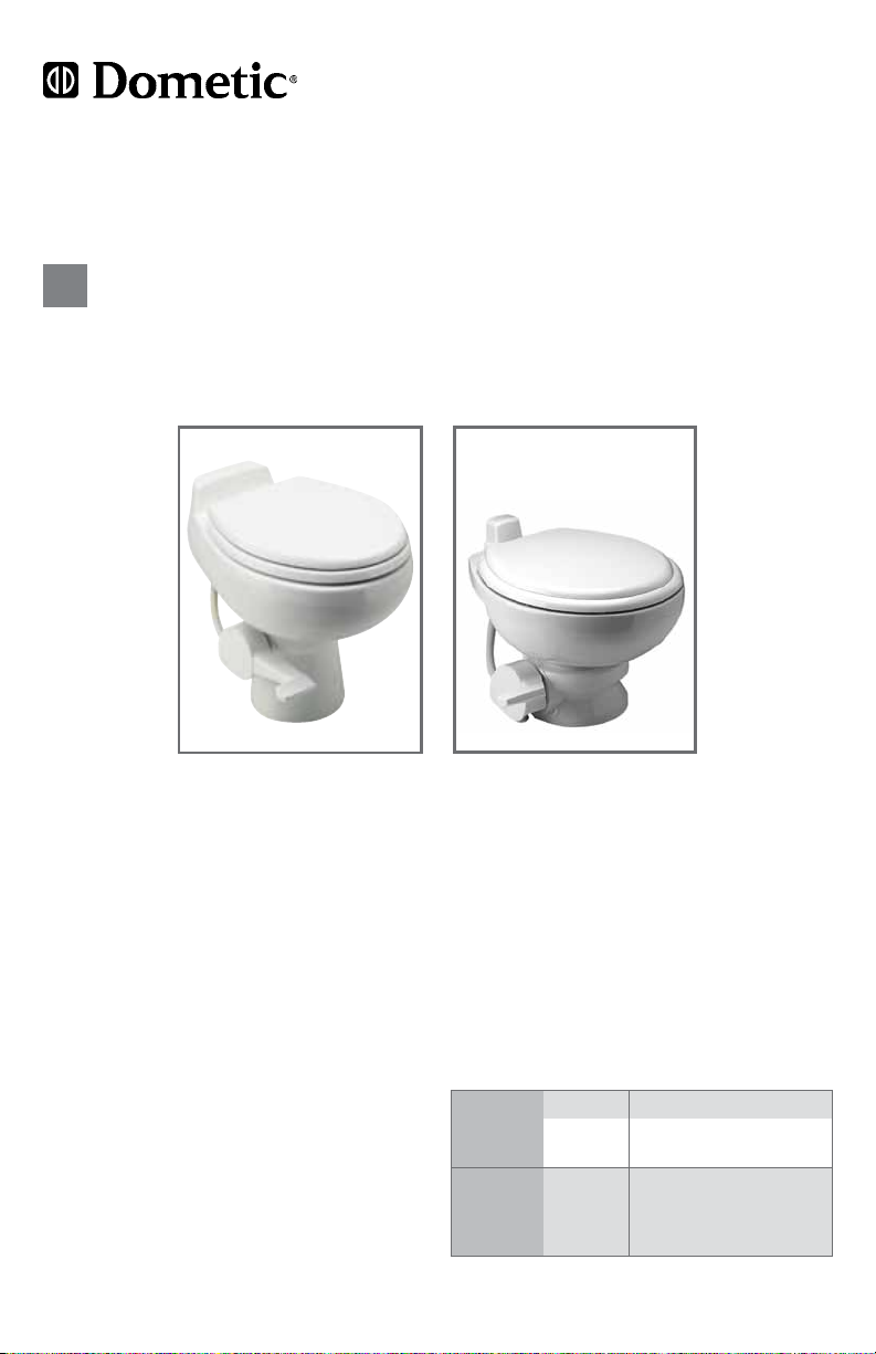
Gravity-Discharge Toilet
EN
Operation manual
500 Series
Toilets
Table of contents
General safety instructions ..............2
Toilet model identication ...............2
Operation ...........................2
Installation ...........................3
Cleaning ............................4
Winterization and storage ............4 - 5
Deodorants and special tissue ...........5
Customer service .....................5
Troubleshooting.................... 6 - 7
Limited warranty ......................8
Model 111
Toilet
Specifications
Water
Supply
Discharge
Specications subject to change without notice.
1
Fitting 0.5 in. NPT
Flow rate
Floor
ange
2.0 gpm / 9.5 lpm
3 in./76 mm ID ABS or
PVC ange connection
directly over waste
minimum
holding tank
Page 2
General Safety Instructions
Caution!
This manual must be read and understood before adjustment, maintenance or service is
performed. Modication of this product can result in property damage.
1. Do not use chlorine or caustic chemicals, such as laundry bleach or drain-opening types, in
the system. These products damage the seals in toilets and dump valves.
2. Do not permit foreign objects (paper towels, paper cups, diapers, sanitary napkins, etc.) to
be ushed through the toilet.
3. Mechanical seal toilets, like Dometic units, are designed to only discharge directly into
a holding tank. Horizontal pipe runs as found in conventional residential or commercial
plumbing systems cannot be accommodated.
4. Toilet bowl must be regularly cleaned and winterized according to “Cleaning” and
“Winterization and Storage” procedures or your warranty coverage may be voided.
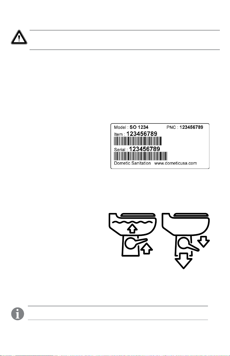
Toilet Model Identification
The model identication label is located on
the toilet base under the pedestal cover
and will show the model number and serial
number. Remove base cover to locate
identication label (see page 5).
Operation
To prepare the Dometic toilet for use, check to be sure water supply to the toilet is
connected. Turn on water supply and check system for leaks. Flush toilet and check for leaks.
To properly use the Dometic toilet, follow these simple instructions:
1. To add water to the toilet, lift or raise
the ush pedal until desired water level
is reached. Generally, more water is
required only when ushing solids.
2. To flush toilet, push pedal all the way
down until contents leave toilet bowl.
Water ow pressures vary at different
locations, therefore holding the ush
pedal down for 4-8 seconds may be
required. Minimum ow at the toilet of
two gpm (7.6 lpm) is required for proper
rim and bowl wash.
3. Release ush pedal by allowing it to snap back,
which permits positive sealing around the ush ball.
4. A small amount of water should remain in bowl.
Note
Holding ush pedal down longer than necessary results in excessive water use.
2
Page 3
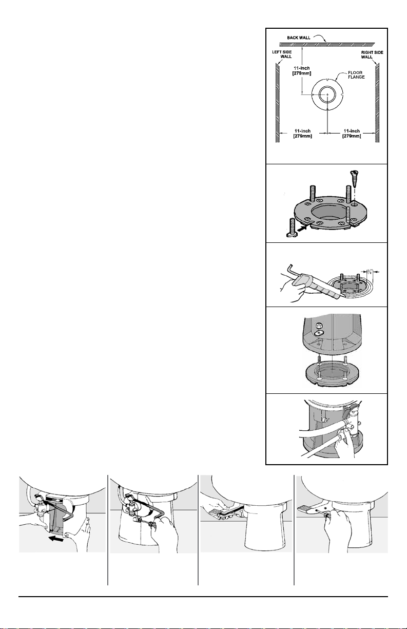
Installation
1. To replace an older toilet, turn off water supply to toilet.
Disconnect water line at toilet water valve. Unscrew oor bolt
nuts and remove toilet. Discard old oor seal and mounting bolts. The old oor ange may be used if it is in good
condition and has fastener holes that are positioned correctly.
Make sure center of oor ange is at least 11 inches
(279 mm) from back wall (Figure A).
NOTE: If old oor ange cannot be used and cannot be
removed, please use a SeaLand Universal Mounting Kit,
available from your Dometic dealer.
2. When installing new oor ange, make certain that the toilet
mounting bolts align properly with Dometic toilet mounting
pattern.
3. Secure ange to oor using at head screws through
countersunk holes in ange. Insert oor bolts into slotted
holes in ange (Figure B).
4. If toilet is being installed in a shower stall, apply a 1/4" thick
by 3/4" wide bead of glazing compound around the circumference of the oor ange (Figure C).
5. Dometic toilet models 111, 510 and 511 will accept handicap
or household decorative seats. Remove existing seat and
replace with new seat if desired.
6. Position oor seal by pressing the oor bolts up through
holes in the seal.
7. Set toilet in place with bolts protruding up through mounting
holes in base (Figure D).
8. Install washers and hex nuts provided with toilet. Tighten
nuts down equally with standard 7/16" open end wrench.
Remove excess glazing compound from around base in
shower stall installation.
9. Connect water supply line to water valve (1/2" NPT) inlet
using appropriate ttings or an extension (Figure E).
10. Turn on water supply and ush toilet to test for leaks.
11. Attach pedestal and pedal covers to toilet base
(see instructions below).
Fig. A
Fig. B
Fig. C
Fig. D
Fig. E
Attaching Pedestal and Pedal Cover
Fig. F
1. Wrap pedestal cover
around base so that it
closes as shown.
2. Tall model – screw
cover together. Short
model – snap together.
3. Slide pedal cover onto
foot pedal rod.
3
4. Secure side plate onto
pedal cover
with screws.
Page 4

Cleaning
For routine cleaning, use SeaLand® Toilet Bowl Cleaner. If
this cleaner cannot be found in your area, contact Dometic
for your nearest dealer. If the cleaner is not available, use
most any non-abrasive bathroom and toilet bowl cleaner.
Please follow label instructions.
FLUSH BALL CLEANING: After a period of time, mineral
deposits from hard water may build up on the ush ball or seal,
resulting in a slow water leak. To prevent this, periodically clean
the ush ball and seal.
1. Remove minor debris from the ush ball and seal by slowly pressing and releasing the ush pedal
several times. This will loosen and rinse debris from the surfaces. Repeat several times for
stubborn buildup.
2. If step 1 does not fully clean the ball and seal, clean with a soft bristle brush and SeaLand Toilet
Bowl Cleaner. Turn off water supply to toilet. Fully clean the top of the ush ball and under the
seal where it contacts the ush ball.
3. After cleaning underside of seal, apply light downward pressure to top of seal while brushing
around full perimeter of seal.
4. Turn on water supply. Press ush lever to open ush ball, and use brush and water to rinse away
cleanser and loosened deposits.
Fig. A
Winterization and Storage
When a Dometic toilet is stored for long periods of time or may be exposed to temperatures
below freezing, the toilet must be winterized or stored according to one of the following
procedures.
Caution
This toilet is not intended for use when exposed to temperatures below freezing.
Caution
Never use automotive-type antifreeze (ethylene glycol) in freshwater systems.
Note
Use nontoxic antifreeze (propylene glycol) designated for potable water systems.
(See vehicle owner’s manual.)
Storage options
Non-toxic Antifreeze Winterization (recommended method)
1. Pour antifreeze in potable water tank according to instructions from antifreeze
manufacturer.
2. Flush toilet several times until antifreeze has owed completely through toilet. For toilets
with hand sprayer, the hand sprayer must be turned on to assure antifreeze is cycled
through the sprayer.
Drain Water from Toilet
1. Turn off water supply to toilet.
2. Remove water supply line from water valve.
3. Place a small container under water valve inlet to catch draining water.
4. Press ush pedal and allow water to completely drain from water valve and vacuum breaker.
5. Leave water line disconnected until threat of freezing temperature has passed.
4
Page 5

Note
Never leave vehicle or premises unoccupied for extended periods of time with
municipal water supply or onboard water pump turned on when there is a possibility
of freezing temperature.
Caution
Toilet warranty does not cover freeze damaged water valve that may result from
improper winterization.
Deodorants and Special Tissue
A gravity-discharge toilet system requires the regular addition of a deodorant product to reduce
waste tank malodors and to help break down holding tank contents. Several factors should be
considered in selecting a deodorant product.
Liquid or Granulated. Liquid products work more quickly by readily going into solution. Granulated powder formulations require less storage space and are less likely to leak if the package is
inadvertently damaged.
How Much Deodorant and How to Add It. The deodorant is added directly into the toilet bowl,
then ushed into the holding tank. Follow bottle or package instructions. Conditions of extremely
warm weather, longer waste holding time and larger tank capacities may require more deodorant
treatment. To maintain optimum odor control, the holding tank should be cleaned thoroughly at
least once or more each season depending on use.
Why Not Use Household Toilet Paper in Your Toilet. Household tissues often contain
adhesives which bond together the paper bers from which the tissue is made. The adhesives
prevent the tissue from breaking apart, and their use in “ultra-low ow” systems can cause system
clogging. SeaLand tissue is especially designed for use in low water toilet systems.
Its rapid dissolving properties minimize the amount of residual paper in the holding tank and allow
deodorizers to work more ef ciently.
SeaLand and Dometic Brands versus Other Brands. We constantly strive to provide our system
owners with effective products that have minimal environmental impact and good value. Many
deodorant products do not measure up to our standards of performance and value.
Customer Service
Toilet model identification
The toilet model identication label is located on the toilet base under the
pedestal cover. Please have this information ready if contacting Dometic for
customer service.
Contact information
There is a strong, worldwide network to assist in servicing and maintaining
your toilet system. For the Authorized Service Center near you, please call
from 8:00 a.m. to 5:00 p.m. (ET) Monday through Friday.
You may also contact or have your local dealer contact the Parts Distributor
nearest you for quick response to your replacement parts
needs. They carry a complete inventory for the Dometic product line.
Telephone: 1-800-321-9886 U.S.A. and Canada
330-439-5550 International
Fax: 330-496-3097 U.S.A. and Canada
330-439-5567 International
Web site: http://www.Dometic.com
5
Page 6

Troubleshooting Guide
Dometic toilet base
assembly
WATER VALVE ASSEMBLY
TOP VALVE CAP
FILTER SCREEN
PEDAL
COVER
Toilet bowl, rear view
(Models 510+, 511+)
VACUUM
BREAKER
ADJUSTING NUT
CAM STRAP
VALVE BODY
WATER VALVE SCREWS
WHITE CAP
CONNECTION
HOSE
SPRING
CARTRIDGE
SHAFT
Toilet bowl, rear view
(Model 111)
VACUUM
BREAKER
BALL SEAL
BOWL SEAL
BAND CLAMP
FLUSH BALL
HOSE
CONNECTION
VACUUM BREAKER/BOWL CONNECTION
Problem Possible Cause Service Instructio
1. Toilet emits odor (ush ball
open).
2. Water will not stay in bowl. a. Loose band clamp.
3. Flush ball will not open. a. Broken shaft.
a. Odor emitting from base of toilet.
b. Plugged holding tank vent line.
b. Improper seal around ush ball
due to dirt or debris on ush ball.
c. Worn or damaged seal.
d. Worn or damaged ush ball.
b. Shaft not fully engaged in the
spring cartridge.
6
VACUUM BREAKER/BOWL CONNECTION
a. Use SeaLand brand deodorants.
b. Clear obstruction from vent line.
a. Tighten band clamp fastener.
b. Inspect ush ball for foreign de-
bris. Clean ush ball if needed.
c. Replace seal.
d. Replace ush ball.
a. Replace shaft.
b. Rotate ush ball slightly until
shaft lines up with square in
spring cartridge and is fully
engaged.
Page 7

Problem Possible Cause Service Instructio
4. Flush ball does not open
completely. (Applies to
short-base units installed on
a step or riser.)
a. Floor ange interferes with ush
ball rotation.
a. Loosen mounting bolts and push
toilet base back. If this does not
solve issue, install a Dometic
Universal Mounting Kit (item no.
385310139 or 385319140) with
existing oor ange.
5. Flush ball will not close
completely.
6. Water does not shut off in toilet
(toilet overows).
7. Hand sprayer leaks. a. Hand sprayer is defective. a. Replace hand sprayer.
8. Water does not enter toilet bowl
properly.
9. Water is leaking from water
valve.
a. Too much friction between ush
ball and ball seal.
b. Water valve screws are too tight.
c. Defective spring cartridge.
a. Not enough clearance between
cam strap and top of water
valve cap.
b. Dir t lodged in water valve seal.
c. Worn or defective water valve.
d. Worn or defective spring
cartridge.
a. Insufcient water ow rate at
toilet.
b. Water valve clogged.
c. Plugged rim wash holes in toilet.
a. Water valve body cracked due to
freeze damage.
b. Water line connection is loose or
not seated properly.
c. Defective water valve.
d. Stripped threads.
a. Lubricate between ush ball and
seal with lubricant (e.g. silicone
spray, furniture polish).
b. Loosen screws slightly.
c. Check spring tension by
pushing ush lever down, then
release it suddenly. If lever does
not snap back to original posi-
tion, replace spring cartridge.
a. Adjust cam strap to have .02” -
.06” (.5mm - 1.5mm) clearance
with top of water valve cap.
b. Dissassemble and clean water
valve.
c. Replace water valve.
d. Replace spring cartridge.
a. Check water ow rate at toilet.
Rate should be 2 gpm (7.6 lpm)
at toilet.
b. Remove and clean screen
located on water valve.
c. Clean holes. If still a problem,
replace toilet bowl.
a. Replace water valve.
b. Insure that threads are not
cross-threaded and tighten.
c. Replace water valve.
d. Replace water valve.
10. Water is leaking from
bottom of toilet base.
11. Water is leaking from rear of
toilet.
12. Water is leaking from the
base/toilet connection.
a. Toilet is not secured to oor.
b. Worn or defective toilet mount-
ing oor seal.
c. Cracked base.
d. Worn or defective oor ange.
a. Loose vacuum breaker.
b. Damaged or defective vacuum
breaker.
c. Cracked or defective toilet bowl.
a. Band clamp may be loose.
b. Ball/bowl seals may be worn or
defective.
7
a. Tighten toilet mounting bolts.
b. Replace oor seal between oor
ange and toilet base.
c. Replace base assembly.
d. Replace oor ange.
a. Make sure vacuum breaker stem
is pushed fully into sealing
grommet in back of bowl.
b. Remove white cap from vacuum
breaker. Flush toilet. If water
leaks during ush, vacuum
breaker needs to be replaced.
c. Replace toilet.
a. Remove plastic base cover (on
applicable models) and tighten
band clamp fastener.
b. Replace ball/bowl seals.
Page 8

Limited Warranty
THE SELLER NAMED BELOW MAKES THE FOLLOWING WARRANTY WITH RESPECT TO
DOMETIC GRAVITY-FLUSH MODELS 510+, 510PS, 511, 511PS, AND 111 ONLY
1. TWO-YEAR LIMITED WARRANTY
1A. This Limited Warranty will be in effect for two years from the date of purchase.
1B. This Limited Warranty is made only to the First Purchaser (hereinafter called the “Original Purchase r”) who
acquired the product for Original Purchaser’s personal, family, or household-type use. The Original Purchaser should retain a copy of the sales receipt or invoice as evidence of the date of purchase because
proof of purchase is required to obtain warranty service.
1C. If this product is placed in commercial or business use, it will be warranted, to the Original Purchaser only, to
be free of defects in material and workmanship for a period of 90 days from the date of purchase.
1D. This warranty covers all parts of the Dometic toilet which is warranted to be free of defects in material and
workmanship under normal use. This warranty does not cover conditions unrelated to the material and
workmanship of the product. Such unrelated conditions include, but are not limited to, (a) faulty installation
and any damage resulting from such; (b) the need for normal maintenance and any damage resulting from
failure to provide such maintenance; (c) failure to follow Seller’s instruc tions for use of this product, including failure which may result from not following winterization procedures; (d) any accident that results in
damage to this product; (e) scratching or staining of any ceramic or plastic component; and (f) acts of God,
or misuse of any part of this product and any alteration by anyone other than the Seller.
1E. For Original Purchaser (ONLY) to obtain the benets of this Warranty during the 2-year period (fo r personal
use) or 90 -day period (for commercial use), the following shall apply:
(a) Or iginal Purchaser shall contact the loc al dealer from whom the product
was purchased; or cont act the Seller Customer Service Department at
1-800-321-9886 (8 a.m.-5 p.m. ET, USA) and provide the local dealer or
Seller Customer Ser vice Department with sales receipt or invoice, product
model and serial number from product. The product model identication
label is located on the toilet base unde r the pedestal cover (see illustration).
(b) If product, while still under warranty, is returned to local dealer where
purchased, the local dealer will re pair, replace or refund the product per this
Warranty and as authorized by the Seller. Seller will provide necessary
replacement parts or product free of charge to Original Purchaser, including
freight on such replacement par ts or product, and Seller will pay direct labor
charge s for such repair or replacement.
(c) Under no circumstances will Seller pay or be liable for any of Original Purchaser’s or dealer’s travel
charge s or other expenses associated with bringing the product or recreation vehicle to the dealer for
repair, for providing dealer with acces s to the product or vehicle, or for downtime of the product or
vehicle.
(d) Original Purchaser may be required to return defe ctive product or parts when requeste d by Seller;
in such event, Seller will pay related freight costs.
2. THE SELLER DOES NOT AUTHORIZE ANY PERSON OR COMPANY TO CREATE OR EXTEND ANY
WARRANTY OBLIGATIONS OR LIABILITY ON ITS BEHALF.
3. RE PAIR OR REPLACEMENT OF, OR REFUND FOR, DE FECTIVE PRODUCT, AT SELLER’S OPTION,
SHALL BE THE ORIGI NAL PURCHASER’S SOLE REMEDY UNDER THIS LIMITED WARRANTY.
IN NO EVENT SHALL S ELLER BE LIABLE FOR PURCHASER’S INCIDENTAL OR CONSEQUENTIAL
DAMAGES. SOME STATES DO NOT ALLOW THE EXCLUSION OR LIMITATION OF INCIDENTAL OR
CONSEQUENTIAL DAMAGES, SO THE ABOVE LIMITATION OR EXCLUSION MAY NOT APPLY TO
YOU.
4. SELLER DISCLAIMS ALL OTHER WARRA NTIES WITH RESPECT TO THE PRODUCT, WHETHER
EXPRESS OR IMPLIED, AND SPECIFICALLY DISCL AIMS THE IMPLIED WARRANTIES OF
MERCH ANTABILITY AND FITNES S FOR A PARTICUL AR PURPOSE. SOME STATES DO NOT ALLOW
LIMITATIONS ON IMPLIED WARRANTIES OR HOW LONG AN IMPLIED WARRANTY LASTS, SO THE
ABOVE LIMITATION MAY NOT APPLY TO YOU.
5. THIS WARRANT Y GIVES YOU SPECIFIC LEGAL RIGHTS, AND YOU MAY ALSO HAVE OTHER
RIGHT S WHICH VARY FROM STATE TO STATE.
Locati on of produc t ID label
SELLER:
Dometic Corporation - Sanitation Div.
13128 SR 226
Big Prairie, Ohio 44611 USA
330-439-5550
® Registered; ™ Trademar k of Dometic Co rporation
8
© Dometic Corporation
60 0340 098 02 12/12
 Loading...