

Page 1
®
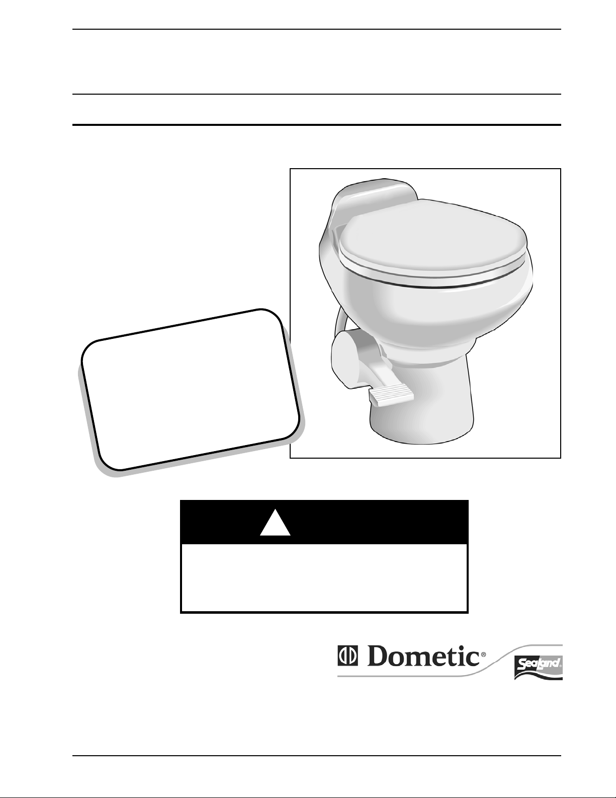
VACUFLUSH
SANITATION SYSTEM
OWNER’S MANUAL
500
IMPORTANT NOTICE
VacuFlush
must be installed according to
Dometic’s recommended procedures.
Do not attempt installation without
first contacting a SeaLand
®
sanitation systems
Product certified dealer or
Dometic Corporation.
Plus
Series, 1000 Series, Model 706 Toilets
WARNING
!
This manual must be read and understood
before adjustment, maintenance, or service
is performed. Modification of this product
can result in property damage.
Dometic Corporation • Sanitation Systems
13128 State Rt. 226, P.O. Box 38
Big Prairie, OH 44611-0038 USA
SeaLand Product Hotline 1-800-321-9886
(8:00 a.m. - 5:00 p.m. ET)
1
Page 2
TABLE OF CONTENTS
Page Page
Product Features . . . . . . . . . . . . . . . . . . . . . . 2
Marine Sanitation Regulations. . . . . . . . . . . . 3
Important Information Before Operation . . . . 3
Key System Components . . . . . . . . . . . . . 4 - 5
System Start Up . . . . . . . . . . . . . . . . . . . . . . 5
Proper Cleaning . . . . . . . . . . . . . . . . . . . . . . 5
Winterizing . . . . . . . . . . . . . . . . . . . . . . . . . . 5
Maintenance . . . . . . . . . . . . . . . . . . . . . . . . . 6
Spare Parts . . . . . . . . . . . . . . . . . . . . . . . . . . 6
VacuFlush Maintenance Kit . . . . . . . . . . . . . . 7
Ordering Parts . . . . . . . . . . . . . . . . . . . . . . . . 7
Toilet Model Identification . . . . . . . . . . . . . . . 7
WARNING – HIGH VOLTAGE SYSTEM.
Turn off electrical power before servicing.
Pedestal and Pedal Cover Installation . . . . . . 7
Deodorants and Special Tissue. . . . . . . . . . . 8
Accessories . . . . . . . . . . . . . . . . . . . . . . . . . . 9
Vacuum Tester . . . . . . . . . . . . . . . . . . . . . . . 9
Service Tip . . . . . . . . . . . . . . . . . . . . . . . . . . 9
Troubleshooting Guide . . . . . . . . . . . . . 10 - 12
Parts Lists . . . . . . . . . . . . . . . . . . . . . . . 13 - 20
Dimensional Specifications . . . . . . . . . . . . . 21
Wiring Diagrams . . . . . . . . . . . . . . . . . . . . . 22
Parts Distributors . . . . . . . . . . . . . . . . . . . . . 23
Manufacturer’s One-Year Limited Warranty 24
WARNING – PUMP STARTS AUTOMATICALLY.
Turn off electrical power before servicing.
PRODUCT FEATURES
Dometic brings the technology, comfort and efficiency of VacuFlush Sanitation Systems in an easy-touse and easy-to-maintain package.
• Freshwater Flush
• Eliminates the unpleasant sulfide odors which plague saltwater systems.
• Eliminates the need to draw flush water through the through-hull, seacock and vented loop.
• Significantly extends life of system components by eliminating saltwater and impurities from
accumulating in the system over time.
• Efficient Design
• Consumes a little over a pint of water per flush and allows boat owners to use a small waste tank.
The VacuFlush system fills a ten-gallon (28.4 liter) tank in the same time that an electric toilet fills a
40-gallon (113.6 liter) tank.
• Uses only 4-6 amps per flush on 12 VDC.
• Delightful Operation
• Simple one-lever flush control. No complex instructions needed.
• Comfortable adult-sized seat.
• Large water surface maintains clean bowl.
• Vitreous china bowl.
• Reliability is Built-In
• USCG Certified Type III Marine Sanitation Device.
• No impellers or macerators – vacuum pump motor can run dry without burning up. No dynamic seals.
• Vacuum tank and vacuum generator design eliminates clogging problems associated with other
systems.
• Dispose of Sewage Conveniently and Safely
• Toilet can be used without discharging sewage into sensitive waters.
• Holding tank discharge is at a dockside pump or at sea with optional overboard discharge.
• No portable toilet tanks to haul or dump.
• Backed by the Best in Service and Quality
• The VacuFlush system is from the leader in marine sanitation.
• Worldwide parts availability and technical backup.
Dometic reserves the right to change specifications without notice.
2
Page 3
MARINE SANITATION REGULATIONS
All boats with fixed toilets in U.S. waters and in the waters of some other countries are required to be equipped
with an operable marine sanitation device (MSD). The VacuFlush system is a holding tank or Type III system as
defined by the U.S. Coast Guard.
Type III systems are designed to permit operation of the toilet without the direct discharge of untreated waste
after every flush. This means onboard toilet facilities can be used when the boat is near swimmers, beaches or
shellfish beds.
Type III systems can be discharged at marina dockside pump-out stations or, if in coastal waters, a minimum of
three miles offshore. Overboard discharge capability must remain secured while within the three-mile
limit. The overboard discharge pump is activated by a keyed switch located in the toilet compartment. This key
should be removed at all times except when discharge pump is operating.
Federal legislation has provided grants to private marinas to install dockside pumps especially in coastal water.
It is estimated that over 3,500 pump-out stations, in total, will be added due to this legislation.
Sewage from any source should not be discharged directly into our waters. If you are interested in learning more
about this issue, please contact SeaLand at the phone number or address listed on the back page of this manual.
Request Clean Water Notebook, Volumes 1 and 2.
IMPORTANT INFORMATION BEFORE OPERATION
1. Fill freshwater tank and add deodorant to holding tank through toilet bowl.
(See System Start Up Section)
2. Make sure all guests understand the operation of the VacuFlush system
and the instruction label is in plain sight and easy for guests to read.
If this label is not included in this manual, please contact the SeaLand
Product Customer Service Department immediately.
3. Remember the vacuum pump starts automatically. Shut off the system before servicing and do not leave the
boat with toilet system breaker on.
4. Never use drain openers, alcohol, solvents, etc. in the system.
5. If the system does not function properly, refer to the Troubleshooting Section of this manual and repair as
necessary. If problem persists, contact your local SeaLand dealer or see the Parts Distributor section of this
manual.
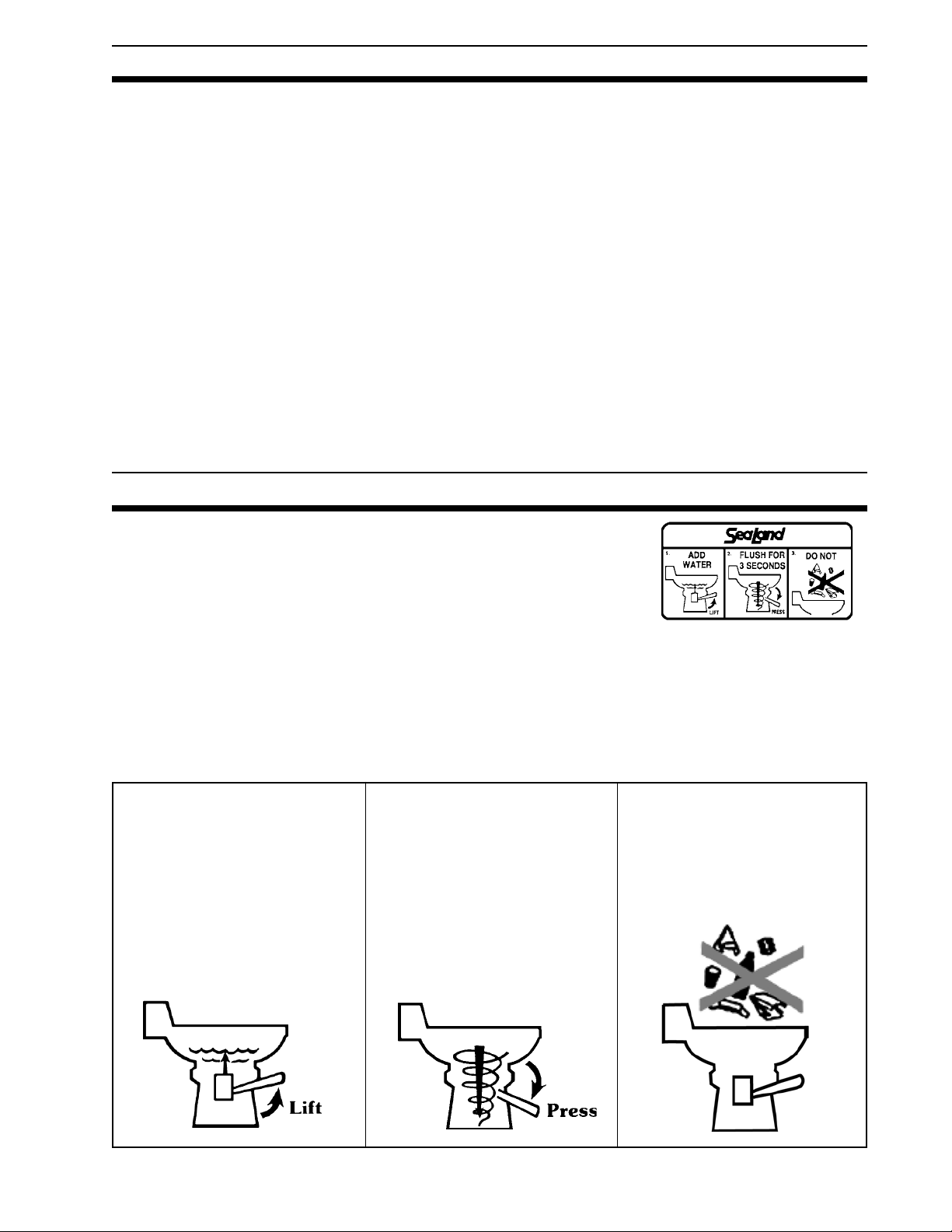
NORMAL OPERATION
1. To add water to the toilet before
using, raise flush lever until desired
water level is reached. Generally, more
water is required only when flushing
solids.
2. To flush toilet, press flush lever
sharply down to the floor until contents
clear bowl. A sharp popping noise is
normal when the vacuum seal is broken and flushing action begins. Be sure
to hold lever down for three (3) seconds. If flush lever is accidentally released before waste clears bowl, do not
attempt to flush toilet again until
vacuum pump stops running. A small
amount of water should remain in the
bowl after flushing.
3. Do not dispose of sanitary napkins
or other non-dissolving items in toilet,
such as facial tissue or paper towels.
These items can cause plugging of the
system. Refer to the Deodorants and
Special Tissue section in this manual
for more information.
3
Page 4
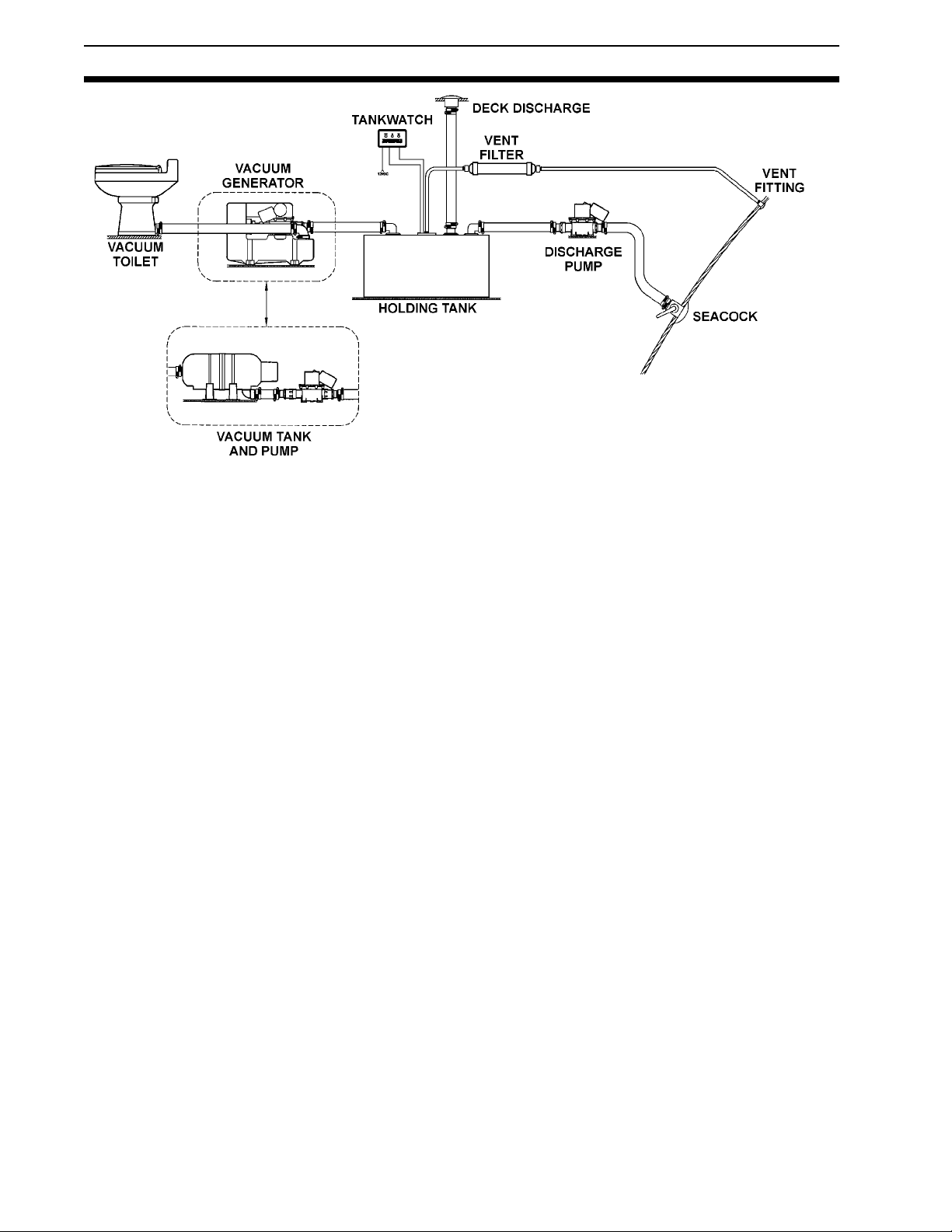
KEY SYSTEM COMPONENTS
Vacuum Toilet: The VacuFlush toilet operates in a way different from other marine toilets. VacuFlush systems use
a small amount of water (a little more than a pint or .5 liter) per flush in addition to a simple vacuum. The toilet is
connected to a pressurized freshwater system. Fresh water is the key to an odor-free bathroom compartment.
VacuFlush toilets are equipped with an integral vacuum breaker which prevents the possible contamination of the
potable water supply.
Vacuum Tank: The vacuum tank stores vacuum energy. System vacuum level is monitored by a vacuum switch
located on the vacuum tank. When this switch senses a drop in vacuum in the system, it automatically signals the
pump to energize and bring the vacuum to operating level. This process is normally completed in less than one
minute. In a properly operating system, the stored vacuum will slowly dissipate between flushes, permitting the
vacuum pump to quickly renew the vacuum.
Vacuum Pump: The vacuum pump is an electric, straight-through bellows type. It is manufactured of long-lasting
polypropylene and draws only 4 to 6 amps of current at 12 VDC. This unique pump design is both an efficient air and
liquid pump that handles solids without a problem. It has two duckbill valves on each side of the pump chamber to
prevent backflow of waste and vacuum.
Vacuum Generator: The vacuum generator combines the vacuum tank and vacuum pump in one unit.
It greatly reduces installation time and eliminates the hose run between the tank and pump. Its compact size makes
it especially well-suited to smaller crafts.
Holding Tanks: Holding tanks from Dometic are made of super-strong, 3/8" (9.5mm) thick polyethylene — 50%
thicker than most other holding tanks. Each unit has a solid, one-piece construction with no seams for unmatched
durability. Tanks come in several capacities and shapes. Contact Dometic for details. A deodorant additive is
required to keep the holding tank odor-free. See Deodorants and Special Tissue section for further information.
TankWatch
The inspection cap in the holding tank contains the micro-float switch units. The adjustable probe assemblies are
flexible polybutylene tubing and are designed to flex when tank contents move.
In-Line Vent Filter: Our SaniGard
smelling clean and pleasant. Heavier-than-air malodors accumulate in the holding tank. The SaniGard vent filter has
a special type of activated filter media to remove these odors before they offend. Each cartridge is good for an entire
season, and is easily replaced for a fresh start. Replacement cartridges are available from your local marine dealer.
Dockside Discharge Deck Fitting: The holding tank is connected to a deck discharge fitting. This fitting, in turn, can
be connected to a dockside pump which may have a rubber, cone-shaped nozzle or a cam lock fitting. Refer to
Accessories section for further information on the NozAll™ fitting which makes using a dockside pump easy and
convenient.
Discharge Pump: Our T-series SaniPump
VDC. The discharge pump has a flow rate of just over 5.25 gallons per minute (11.4 liters per minute). Emptying an
onboard tank usually takes four to six minutes. The T-pump is connected to a through-hull fitting. Check the section
on Marine Sanitation Regulations for information on areas where discharge is allowed.
®
Level Indicator: The TankWatch unit utilizes micro-float switches which activate an indicator panel.
TM
vent filter has special odor-removing filter materials to help keep your boat
TM
discharge pump can run dry without harm and draws just 6 amps at 12
4
Page 5
SYSTEM START UP
1. Turn on inlet water supply.
2. Turn on electrical power to system.
3. Flush water into system by depressing flush lever until water starts flowing to the vacuum pump, approximately 15 seconds. The vacuum pump will run for approximately 60 to 90 seconds until system reaches
operating vacuum level and then will shut off.
PROPER CLEANING
The SeaLand toilet should be cleaned regularly for maximum sanitation and
operational efficiency. You can clean it just as you would a household toilet.
Do not use caustic chemicals, such as drain-opening types, as they
will damage the seals.
®
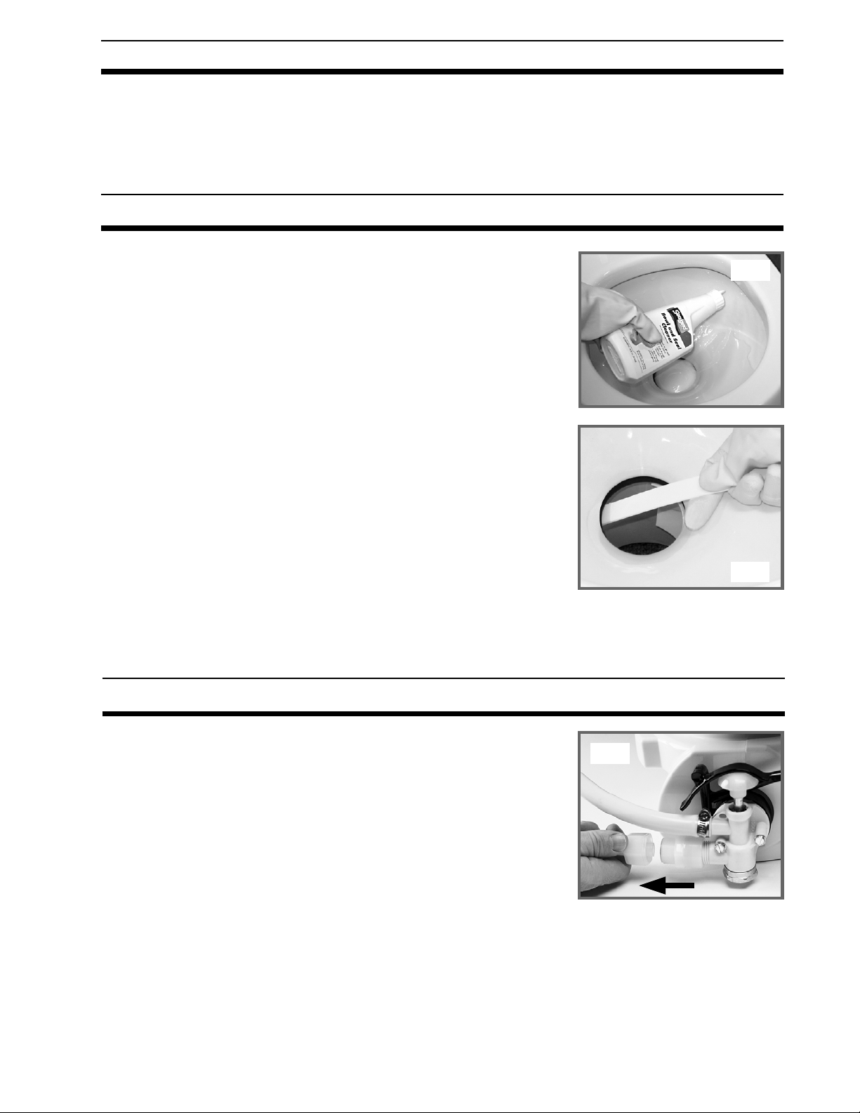
BOWL CLEANING: For stubborn stains, use SeaLand
Cleaner (Fig. A). It’s manufactured especially for use with SeaLand toilets.
In certain locations where water is hard, a build-up of lime may dull the toilet
bowl finish. Restore the shine with this SeaLand cleaner. If you cannot find
it in your area, contact SeaLand for your nearest dealer. If the cleaner is not
available, you can also use Bar Keepers Friend
sary to vigorously scrub with either product. Please follow label instructions.
SEAL CLEANING: After an extended time, mineral deposits from hard
water can build up under the edge of the rubber bowl seal, resulting in a
slow leakdown of water from the bowl. To prevent this mineral build-up,
periodically clean under the bowl seal with SeaLand Bowl and Seal Cleaner
(Fig. B).
1. Shut off water supply.
2. Apply cleaner onto the seal cleaning tool (supplied with new toilet), open
the flush ball by pressing on flush lever, and scrub under the seal. Make
sure to push bristles between bottom of seal and top of flush ball
surface to scrub all parts of seal that come into contact with flush ball.
3. Close ball and wait 2-3 minutes.
4. Open flush ball. Use brush and water to rinse away cleanser and loosened deposits.
®
cleanser. It is not neces-
Bowl and Seal
Fig. A
Fig. B
WINTERIZING
At the end of each season, the SeaLand toilet should be winterized for
storage, by either draining or using potable water-safe antifreeze in the
system.
To drain:
1. Thoroughly flush system with fresh water.
2. Empty holding tank.
3. Shut off water supply to toilet(s), and remove inlet waterline (Fig. C).
Do not remove brass cap on bottom of valve.
4. Press flush lever until all water is drained from toilet(s).
To use antifreeze:
1. Drain potable water tank.
2. Add freshwater antifreeze to potable water tank.
3. Flush potable water antifreeze and water mixture through toilet(s) and into the waste holding tank. Each
installation is different, so amounts may vary. User discretion is required to assure adequate protection.
4. Empty holding tank.
NOTE: Use nontoxic antifreeze designated for potable water systems. (See vehicle owner’s manual.)
CAUTION: Never use automotive-type antifreeze in freshwater systems.
5
Fig. C
Page 6
MAINTENANCE
Maintenance intervals and normal parts replacement vary widely depending on numerous factors such as: type
of vessel, frequency of system use, quality of flushing water, etc. The chart below is intended strictly as a
general guideline. Owner discretion and consideration of actual usage must be the first basis for determining
proper maintenance levels.
Maintenance Procedure
Follow cleaning procedures (page 5).
Tighten all clamps, including base clamp ring.*
Check all wire connections.
Check & tighten water valve mounting screws.
Clean filter screen in water valve.
Check pump and in-line valves.
Check toilet seals.
Check vacuum breaker.
Check water valve.
Part Number
—
—
—
—
—
385310076 (2)
385316140
385316906
385314349
Approximate Maintenance Level
Monthly
Annually
Annually
Annually
Annually
2-3 years or as needed
3-5 years or as needed
3-5 years or as needed
3-5 years or as needed
*See Base Assembly - Page 10.
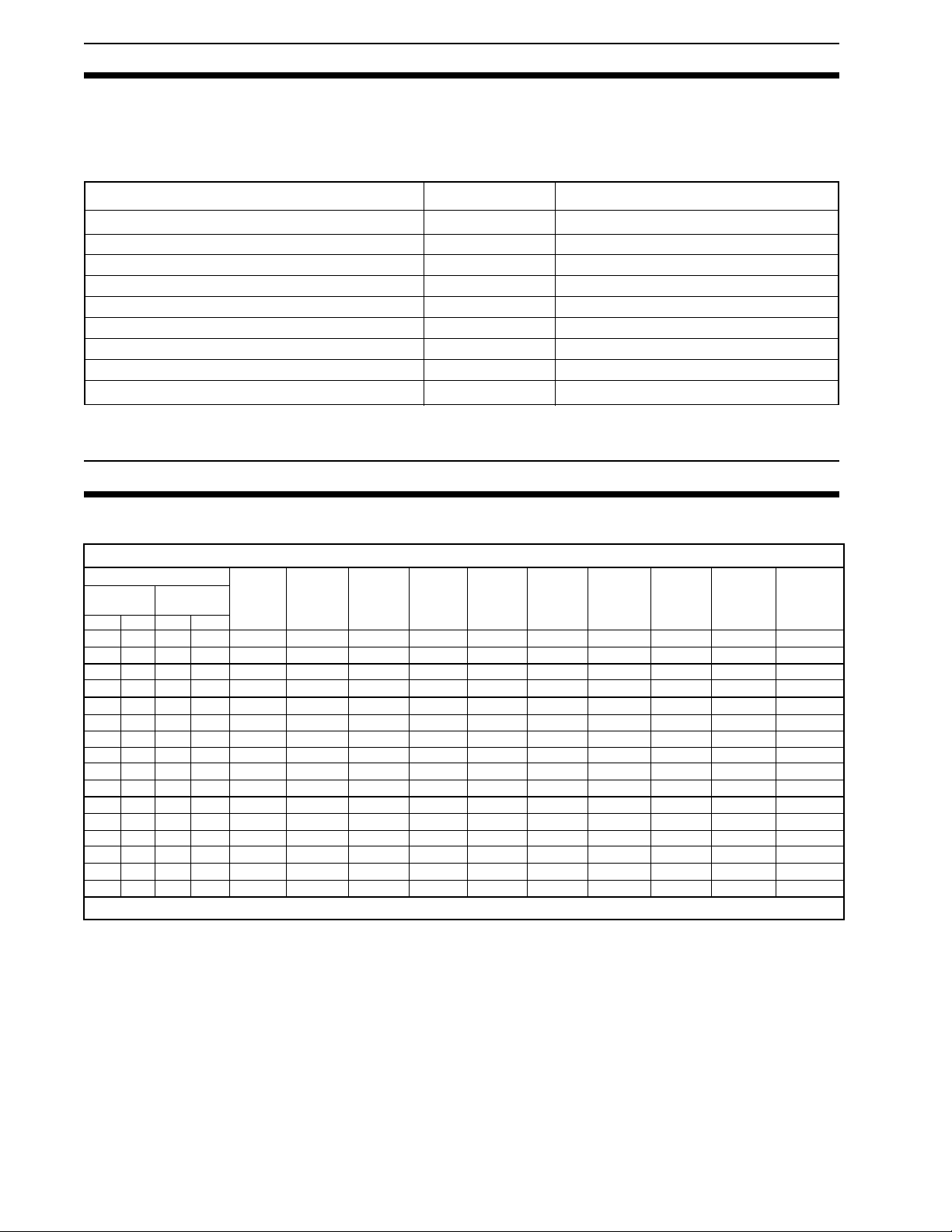
SPARE PARTS
To calculate total spare parts required, determine number and type of toilets and pumps.
On Board Spare Parts Calculation Chart: (Per System)
Type of System
Toilet Series
& Quantity
500+
1000
1
2
1
2
1
2
3
4
5
6
1
2
3
4
5
6
Pump Series
& Quantity
S
1
2
1
2
Toilet
Seal
Kit
M *
1 each
1 each
1 each
1 each
1
1 each
1
1 each
1
1 each
1
2 each
1
2 each
1
2 each
1
1 each
1
1 each
1
1 each
1
2 each
1
2 each
1
2 each
Per Vessel: Vacuum Tester – 530002 (1 each) & Owner’s Manual – (1 each)
Toilet
Water
Valve
Kit
1 each
1 each
1 each
1 each
1 each
1 each
1 each
2 each
2 each
2 each
1 each
1 each
1 each
2 each
2 each
2 each
S Pump
Duckbill
Valve Kit
2 each
2 each
2 each
2 each
M Pump
Duckbill
Valve Kit
4 each
4 each
4 each
4 each
4 each
4 each
4 each
4 each
4 each
4 each
4 each
4 each
Toilet
Vacuum
Breaker
1 each
1 each
1 each
1 each
2 each
2 each
2 each
1 each
1 each
2 each
2 each
2 each
Vacuum
Tank
Vacuum
Switch
1 each
1 each
1 each
2 each
1 each
1 each
1 each
2 each
Toilet
Ring/
Clamp
Kit
1 each
1 each
1 each
2 each
1 each
1 each
1 each
2 each
Toilet
Ball/Shaft
Cartridge
Kit
1 each
1 each
1 each
1 each
1 each
1 each
2 each
1 each
1 each
1 each
1 each
2 each
Vacuum
Generator
Switch
Kit
1 each
1 each
1 each
2 each
1 each
1 each
1 each
2 each
Low-Profile
Vacuum
Generator
Switch Kit
1 each
1 each
1 each
2 each
1 each
1 each
1 each
2 each
* M series pump parts information is contained in a separate M-Pump Owner’s Manual.
6
Page 7
VACUFLUSH MAINTENANCE KIT
The VacuFlush Maintenance Kit contains replacement parts used in routine maintenance of VacuFlush toilets. A “must” for those who cruise to remote locations. The kit includes vacuum tester,
water valve, seal kit, duckbill valves (4) and an
owner’s manual in a convenient storage container.
VacuFlush
Maintenance Kit
(item number 310228)
ORDERING PARTS
Dometic is ready to assist you in the event service is required. Before calling, please have the following information available. Your cooperation in having this information ready is appreciated and allows us to better meet your
needs. Please refer to the Parts Distributor list on Page 23.
1. Toilet Model Number (See following section.)
2. Serial Number
3. Part Number, Description and Quantity (See Parts information.)
TOILET MODEL IDENTIFICATION
DOMETIC CORPORATION
P.O. BOX 38, 13128 STATE RT 226 (800) 321-9886
BIG PRAIRIE, OH 44611 USA
MODEL NO.
SERIAL NUMBER
000
000000
The above label is located on the toilet base and will show the model number and serial number. If label is not
available, please refer to the Dimensional Specifications section for toilet model identification.
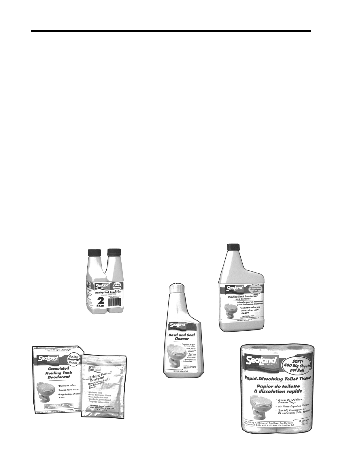
PEDESTAL AND PEDAL COVER INSTALLATION
1. With the pedestal cover open, place the back half
against the side of the base opposite the flush lever.
Rotate the pedestal cover counterclockwise around the
back of the base, then move the front half into place.
2. Tall base unit only, secure with mounting screw.
For short base units, simply snap cover closed.
3. Slide pedal cover onto foot pedal rod.
4. Attach pedal cover side plate and secure with
two (2) mounting screws. For short base units,
secure front screw, then press foot pedal down
completely to secure second screw.
1
2
3
7
4
Page 8
DEODORANTS AND SPECIAL TISSUE
Your VacuFlush sanitation system requires the regular addition of a deodorant product to reduce malodors and
to help break down holding tank contents. Several factors should be considered in selecting a deodorant
product.
Liquid or Granulated: Liquid products obviously work more quickly by readily going into solution. Granulated
powder formulations, on the other hand, have the advantage of requiring less storage space and are less likely
to leak if the package is inadvertently damaged.
Formaldehyde versus Non-Formaldehyde: Dometic manufactures both types of deodorants. Generally
speaking, formaldehyde formulas control odor very effectively at all temperatures and with all degrees of water
hardness. SeaLand Environment-Friendly brand, which is formaldehyde free, is similarly effective.
Environmental Hazards: If you would like further information on the impact of holding tank deodorants, call or
write Dometic at the number and address listed on the back page of this manual. Request a copy of Clean
Water Notebook, Volume 5, which provides complete information in this regard.
How Much Deodorant and How to Add It: The deodorant is added directly into the toilet bowl, then flushed
into the holding tank. Follow bottle or package instructions. Conditions of extremely warm weather, longer
waste holding time and larger tank capacities may require more deodorant treatment. Also, to maintain optimum efficiency in odor control, the waste holding tank should be cleaned thoroughly at least once or more each
season depending on use.
Why Not Use Household Toilet Paper in Your SeaLand Toilet. Household tissues often contain adhesives
which bond together the paper fibers from which the tissue is made. The adhesives prevent the tissue from
breaking apart, and their use in “ultra-low flow” systems can cause system clogging. SeaLand tissue is especially designed for use in low water toilet systems. Its rapid dissolving properties minimize the amount of
residual paper in the holding tank and allow deodorizers to work more efficiently.
SeaLand versus Other Brands: Dometic constantly strives to provide our system owners with effective
products that have minimal environmental impact and good value. Many other deodorant products do not
measure up to our standards of performance and value.
®
Liquid
Part No.
379114032
SeaLand® Liquid
Deodorant
Two 8-oz. bottles
Part No.
379224008
SeaLand® Granulated
Deodorant
Six 2-oz. pouches
SeaLand
Cleaner
16-oz. bottle
Part No.
379314016
SeaLand
Deodorant -
Environment Friendly
32-oz. bottle
®
Part No.
379626002
SeaLand
Rapid-Dissolving
Toilet Tissue
Four 400-sheet rolls
Part No.
379441204
8
®
Page 9

ACCESSORIES
NozAllTM Pumpout Adapter: The NozAll pumpout adapter
provides an airtight seal between your boat’s deck waste
fitting and the pumpout station nozzle. Just screw your
personal NozAll adapter into your deck fitting, and be assured of an airtight connection for pumping out holding tank
contents. Each item contains a glass-filled nylon NozAll
adapter, gasket and vinyl cap. Item number 343502 (1-1/2"-
11.5 tpi), 343503 (1-1/4"-11.5tpi), or 343504 (1-1/4"-16tpi).
VacuFlush Status Panel: An ideal add-on to any
VacuFlush system. The Status Panel is mounted in the
bathroom compartment. A green light indicates sufficient
vacuum is available for the next flush. A red light indicates
the vacuum level is building and the pump is running. Each
panel has an integral circuit breaker which allows the
system to be shut down at night. Order part number 500012
(12VDC) or 500024 (24/32VDC).
VacuStat™ Indicator Panel: A desirable accessory for
VacuFlush sanitation systems, this panel continuously
monitors the status of vacuum for proper toilet operation.
Brushed metallic finish complements bathroom decor. Order part number 700012 (12 VDC) or 700024 (24 VDC).
Optional Vacuum Generator Shut-down Relay: This
relay can be added to automatically shut down power to
the VacuFlush toilet system to prevent overfilling of the
onboard holding tank. Order part number 310289 (12 VDC)
or 310290 (24 VDC).
NozAll™ Adapter
*Nozzle
*Deck Fitting
*Not included.
VacuFlush
Status Panel
VacuStat
Indicator Panel
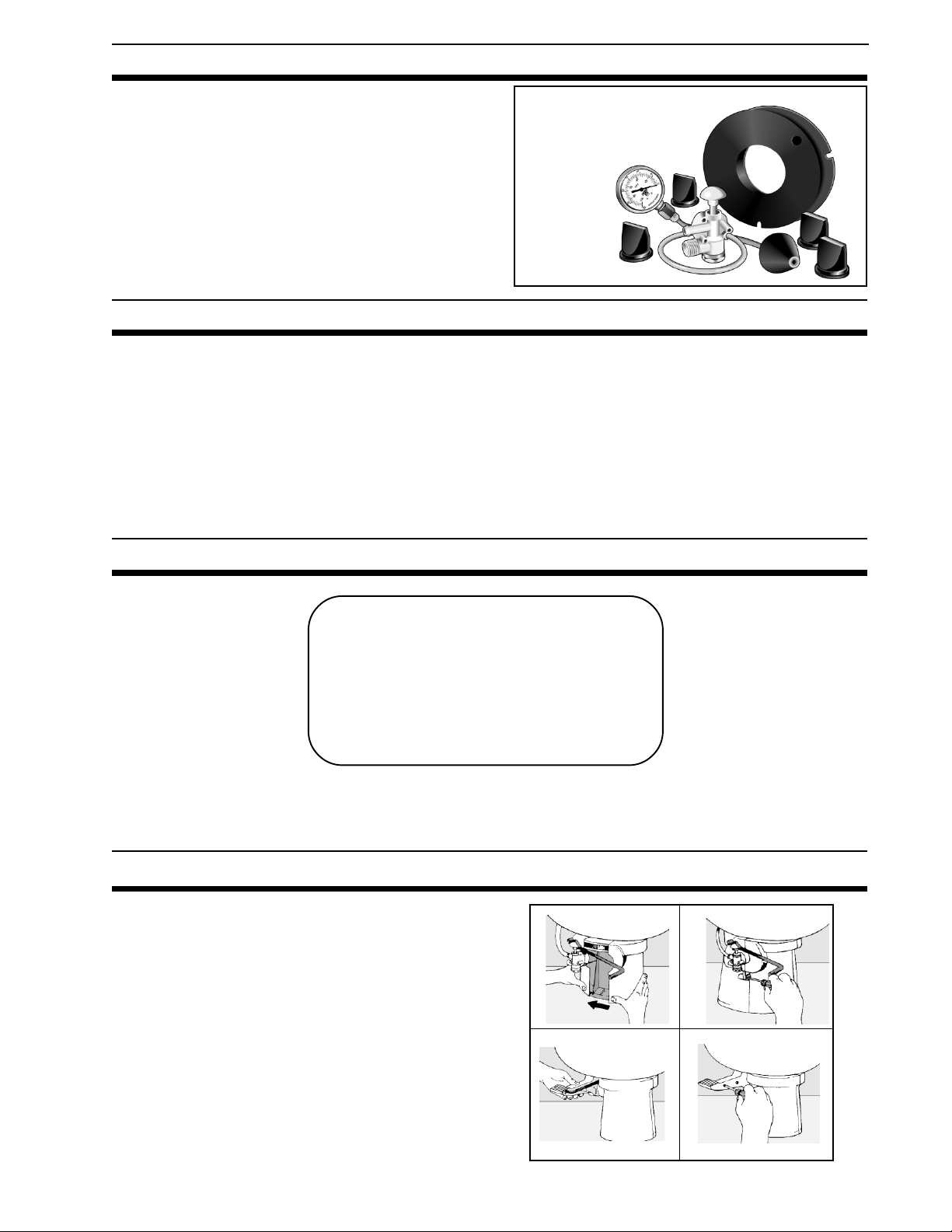
VACUUM TESTER
Dometic has developed a simple tool to assist in
identifying the location of vacuum leaks. The
vacuum tester consists of a vacuum gauge and a
cone-shaped plug. Inserting the plug in the inlet of
the vacuum tank or generator isolates the toilet from
the system. In this way a troublesome leak can
easily be located in either system.
Order only the Vacuum Tester (Part Number
530002) or as part of the complete system mainte-
nance kit (Part Number 310228).
Vacuum Tester
SERVICE TIP
Checking for water leaks behind or under toilets or other appliances can make it difficult to locate the source.
Dripping water at room temperature makes it difficult to feel wetness. Taking four or five sheets of toilet tissue
and wiping all seams and waterline connections offers a simple means of locating the general area of the leakage. Start at the top of the unit since gravity will cause a leak to run downward. When the tissue comes in
contact with the leaking water, it will immediately change texture.
9
Page 10

TROUBLESHOOTING GUIDE
BASE ASSEMBLY
VACUUM
BREAKER
REAR VIEW, VACUUM TOILET
VACUUM BREAKER/BOWL CONNECTION
WHITE CAP
HOSE
CONNECTION
Problem Possible Cause Service Instructions
1. Water will not stay in bowl.
2. Plastic flush ball will not
close completely.
3. Flush ball will not open.
4. Water does not shut off in
toilet (toilet overflows).
a. Loose clamp ring.
b. Improper seal around flush ball due
to dirt or debris on underside of ball
seal.
c. Worn or damaged seal.
d. Worn or damaged flush ball.
a. Too much friction between flush ball
and ball seal.
b. Water valve screws are too tight.
c. Defective spring cartridge.
a. Broken shaft.
b. Shaft not fully engaged in the
spring cartridge.
a. Not enough clearance between cam
strap and top of water valve cap.
b. Dirt lodged in water valve seal.
a. Tighten clamp ring adjusting nut.
b. Inspect flush ball and underside of
seal for foreign objects. Clean under
seal if needed (cleaning tool
available – p/n 600344236).
c. Replace seal.
d. Replace flush ball.
a. Lubricate between flush ball and
ball seal with furniture polish or
cooking spray.
b. Loosen screws slightly.
c. Check spring tension by pushing
flush lever down, then release it
suddenly. If lever does not snap
back into original position, replace
spring cartridge.
a. Replace shaft.
b. Put pressure on shaft from under
the flush ball (pushing into spring
cartridge) until it engages. You may
have to rotate flush ball slightly until
shaft lines up with square in
spring cartridge.
a. Adjust cam strap to have .02"
(.5mm) minimum clearance with top
of valve cap.
b. Disassemble and clean water
valve.
5. Water does not enter toilet
bowl properly.
a. Insufficient water flow rate at toilet.
b. Water valve clogged.
c. Plugged rim wash holes in toilet.
10
a. Check water flow rate at toilet. Rate
should be 2 gpm (7.6 lpm) at toilet.
b. Remove and clean screen located
at inlet of water valve.
c. Clean holes. If still a problem,
replace the toilet bowl.
Page 11

TROUBLESHOOTING GUIDE
Problem Possible Cause Service Instructions
6. Lifting foot pedal does not
add water to the bowl.
a. Too much clearance between the
cam strap and water valve.
a. Adjust cam strap so clearance is
.06 inches (1.5mm) maximum.
7. Water leaking from water
valve.
8. Water leaking from rear of
toilet bowl.
9. Water is leaking from the
base/toilet connection.
10. Vacuum pump running too
often between flushes.
(See Vacuum Tester
Information on page 9.)
a. Water valve body cracked due to
freeze damage.
b. Water line connection is loose or not
seated properly.
c. Defective water valve.
d. Stripped threads.
a. Worn or defective vacuum breaker.
b. Loose vacuum breaker.
c. Cracked or defective toilet bowl.
a. Clamp ring may be loose.
b. Ball seals may be worn or defective.
a. Water leaks out of bowl between
flush ball and ball seal.
b. Vacuum line leak.
a. Replace water valve.
b. Insure that threads are not cross-
threaded and tighten.
c. Replace water valve.
d. Replace water valve.
a. Remove white cap from vacuum
breaker. Flush toilet. If water leaks
during flush, vacuum breaker
needs to be replaced.
b. Secure vacuum breaker
connection.
c. Replace toilet bowl.
a. Remove plastic base cover (on
applicable models) and tighten the
clamp ring.
b. Replace ball seals.
a. Leave small amount of water in
bowl. If water is sucked from bowl,
see problems 1 and 2.
b. Tighten all connections at toilet,
vacuum generator or vacuum
holding tank (including hose
clamps and threaded spin nuts). If
leaks persists, contact SeaLand
Product Customer Service.
11. Vacuum pump will not
shut off.
12.Vacuum pump will not run.
a. A vacuum leak exists.
b. Insufficient vacuum (pump creates
less than 10 inches Hg).
c. Faulty vacuum switch (pump creates
more than 10 inches Hg).
d. Improper wiring.
e. Bellows not pumping.
a. No electrical power.
b. Loose or broken electrical wiring.
c. Improper electrical connections.
d. Faulty vacuum switch.
e. Faulty motor.
f. Shut-down relay prevents pumping.
a. See problem 9b.
b. Isolate pump and use vacuum
gauge to check vacuum levels.
Could be a plugged discharge line
or worn duckbill valves.
c. Replace vacuum switch.
d. Refer to wiring diagram to check
for proper wiring.
e. Tighten set screw in eccentric to
motor shaft. Otherwise, check for
damage to bellows and motor
shaft. Replace if necessary.
a. Check input power, circuit breaker
and fuse.
b. Tighten or reconnect wires at
vacuum pump and tank, vacuum
generator, or vacuum holding tank.
c. Make certain wires at vacuum
switch are connected to the “B”
terminals.
d. To check vacuum switch, short
across “B” terminals with jumper
wire.
e. Replace motor.
f. Empty the holding tank.
11
Page 12

TROUBLESHOOTING GUIDE
Problem Possible Cause Service Instructions
13.Vacuum pump is running too
slow, overheating, blowing
fuses or circuit breaker.
a. Gear motor is worn or defective.
b. Plugged vent line or vent filter.
c. Blockage in discharge line.
d. Improper wire size.
e. Improper voltage.
f. Vacuum pump bellows clogged
with tissue.
a. Check motor and replace if
necessary.
b. Disassemble and clean out vent
line. Replace vent filter if
necessary.
c. Disassemble and clean discharge
line. Be certain that in-line valves
(duckbill valves) and seacock are
in proper position.
d. Wire size too small. Check
electrical diagram for proper wire
size for voltage of pump used.
e. Check input power for low voltage.
f. Remove and clean bellows
assembly. (When flushing toilet,
using more water may alleviate
this problem.)
14.Toilet will not flush.
(No vacuum.)
See problems 3 and 15
if necessary.
15.Blockage between toilet and
vacuum generator.
a. There is a blockage in the system.
b. Pump will not run.
c. Duckbill valves in vacuum pump
are inverted due to blocked
discharge line or an attempt to
pump out against closed seacock.
a. Collapsed vacuum line.
b. Sharp bends or kinks in vacuum
hose.
c. Improper operation of toilet.
d. Foreign objects were flushed down
toilet.
a. Open flush ball and check the 1-
inch (25mm) orifice at the bottom
of the base for blockage and
dislodge it. Never use drainopening or other household
plumbing chemicals.
If blockage is not in base, it may
be found in these locations:
• outlet of vacuum tank
• inlet of vacuum generator
• diptube of vacuum generator
• inlet of vacuum pump
b. See problem 12.
c. Replace duckbill valves, making
sure they point in the correct
direction.
a. Inspect vacuum line for collapsed
condition and replace line if
needed.
b. Inspect vacuum hose for kinks or
bends. If less than 8.5-inches
(216mm) radius on any bend,
reposition hose to achieve
minimum 8.5-inch bend radius.
c. Make sure each person using
toilet knows correct procedure.
d. DO NOT flush any non-dissolving
items (i.e. sanitary napkins, facial
tissue, wet strength tissue, paper
towels, etc.) or excessive toilet
tissue down toilet. Rapid-dissolving SeaLand brand toilet tissue is
best.
16.Pump emits odor.
a. Loose or defective hose
connection on pump.
b. Loose intake or discharge fittings
on pump.
c. Worn, torn or punctured pump
bellows (vacuum generator) or
diaphragm (vacuum holding tank).
12
a. Tighten connections or replace
hose and make new connections.
b. Tighten intake or discharge fittings
on pump. Replace nipples or
adapters if necessary.
c. Replace pump bellows or
diaphragm.
Page 13

PARTS LIST
MODEL 706
Item Part No. Description
1
385344436
385344437
2
385310676
385310736
3
385310048
4
385316140
*5
385310132
385310133
6
385310064
7
385318864
8
600341549
9
385310744
10
385314349
11
385310117
385310118
12
385318162
13
600345377
600340177
14
385316906
15
385310108
385310109
16
385236096
17
385310696
385310782
* Includes items 3 through 12, 15 and 16.
Seat Assembly, White
Seat Assembly, Bone
China Bowl, White
China Bowl, Bone
Ring and Half Clamp Kit
®
Teflon
and Rubber Seal Kit
Base Kit, White
Base Kit, Bone
Mounting Kit
Funnel Kit
Floor Flange Seal
Flush Lever Kit (includes item 16)
Water Valve Kit
Pedal Cover Kit, White
Pedal Cover Kit, Bone
Ball, Shaft & Cartridge Kit (includes item 16)
Supply Hose, White
Supply Hose, Bone
Vacuum Breaker Kit
Pedestal Cover Kit, White
Pedestal Cover Kit, Bone
Spring Cartridge Assembly
Vacuum Breaker Cover, White
Vacuum Breaker Cover, Bone
MODEL 1147 & 1148
Item
1
2
3
4
*5
6
7
8
9
10
11
12
13
14
* Includes items 3 through 12.
Part No.
1147
385340590
385340591
385310615
385310616
385310677
600343534
385310685
385310783
385310679
385310785
385310680
385310682
385310786
385314349
385310683
385310681
385310025
385310048
600345377
600340177
385316906
1148
385340590
385340591
385310615
385310616
385310677
600343534
385310686
385310784
385310679
385310785
385310680
385310682
385310786
385314349
385310683
385310681
385310025
385310048
600345377
600340177
385316906
Description
Seat Assembly, White
Seat Assembly, Bone
China Bowl, White
China Bowl, Bone
®
Teflon
& Rubber Seal Kit
Base Ring
Base Kit, Right-hand Discharge - White
Base Kit, Right-hand Discharge - Bone
Base Kit, Rear Discharge - White
Base Kit, Rear Discharge - Bone
Mounting Kit, White
Mounting Kit, Bone
Discharge Kit
Flush Pedal Kit - White (includes item 10)
Flush Pedal Kit - Bone (includes item 10)
Water Valve Kit
Spring Cartridge Kit
Ball, Shaft & Cartridge Kit (includes item 10)
Ring & Half Clamp Kit, White
Ring & Half Clamp Kit, Bone
Supply Hose, White
Supply Hose, Bone
Vacuum Breaker Kit
13
Page 14

PARTS LIST
MODEL 506+
MODEL 508+
MODEL 547+ MODEL 548+
14
Page 15

PARTS LIST
Item
1
2
3
4
5
6
7
8
*9
10
11
12
13
†14
15
16
506+ 508+ 547+ 548+
385343830
385343832
385343898
385343902
385343900
385310739
385310740
385310741
385310742
385310743
385310048
385316140
385310064
385310108
385310109
385310110
385310600
385310603
600341549
385318864
385318162
385310177
385310188
385310117
385310118
385310119
385310593
385310596
385314349
385236096
385310744
385310943
385310133
385310134
385310607
385310610
600345377
600340177
385316906
385343830
385343832
385343898
385343902
385343900
385310739
385310740
385310741
385310742
385310743
385310048
385316140
385316323
385310111
385310112
385310113
385310173
385310203
NA
385318741
385318162
385310177
385310188
385310114
385310115
385310116
385310175
385310193
385314349
385236096
385310578
385310126
385310127
385310128
385310171
385310213
600345377
600340177
385316906
385343830
385343832
385343898
385343902
385343900
385310739
385310740
385310741
385310742
385310743
385310048
385316140
385316323
385310674
385310613
385310745
385310746
385310747
NA
385318741
385318162
385310177
385310188
385310114
385310115
385310116
385310175
385310193
385314349
385236096
385310578
385310665
385310614
385310748
385310749
385310750
600345377
600340177
385316906
385343830
385343832
385343898
385343902
385343900
385310739
385310740
385310741
385310742
385310743
385310048
385316140
385316323
385310136
385310137
385310138
385310174
385310223
NA
385318741
385318162
385310177
385310188
385310114
385310115
385310116
385310175
385310193
385314349
385236096
385310578
385310129
385310130
385310131
385310172
385310218
600345377
600340177
385316906
Description
HushFlush Seat Assembly, White
HushFlush Seat Assembly, Bone
HushFlush Seat Assembly, Platinum
HushFlush Seat Assembly, Ebony
HushFlush Seat Assembly, Teal
China Bowl Kit, White
China Bowl Kit, Bone
China Bowl Kit, Platinum
China Bowl Kit, Ebony
China Bowl Kit, Teal
Ring & Half Clamp Kit
®
Teflon
& Rubber Seal Kit
Mounting Kit
Pedestal Cover Kit, White
Pedestal Cover Kit, Bone
Pedestal Cover Kit, Platinum
Pedestal Cover Kit, Ebony
Pedestal Cover Kit, Teal
Floor Flange Seal
Funnel Kit
Ball/Shaft/Cartridge Kit, White/Bone/Plat.
Ball/Shaft/Cartridge Kit, Ebony
Ball/Shaft/Cartridge Kit, Teal
Pedal Cover Kit, White
Pedal Cover Kit, Bone
Pedal Cover Kit, Platinum
Pedal Cover Kit, Ebony
Pedal Cover Kit, Teal
Water Valve Kit
Spring Cartridge Assembly
Flush Lever Kit (includes item 13)
Base Kit, White
Base Kit, Bone
Base Kit, Platinum
Base Kit, Ebony
Base Kit, Teal
Supply Hose, White
Supply Hose, Bone
Vacuum Breaker Kit
* Includes item 12.
† Includes items 2 through 14.
15
Page 16

PARTS LIST
MODEL 1006
MODEL 1008
MODEL 1047
MODEL 1048
16
Page 17

PARTS LIST
Item
1
2
3
4
*5
6
7
8
9
10
11
12
13
14
15
16
1006
385344436
385344437
385344438
385310615
385310616
385310585
385310048
385316140
385310132
385310133
385310607
385310064
385310108
385310109
385310600
385318864
385310117
385310118
385310593
385314349
385310579
385318162
385310177
600345377
600340177
385316906
385236096
600341549
1008
385344436
385344437
385344438
385310615
385310616
385310585
385310048
385316140
385310126
385310127
385310171
385316323
385310111
385310112
385310173
385318741
385310114
385310115
385310175
385314349
385310578
385318162
385310177
600345377
600340177
385316906
385236096
NA
1047
385344436
385344437
385310615
385310616
385310048
385316140
385310665
385310614
385316323
385310674
385310613
385318741
385310114
385310115
385314349
385310578
385318162
600345377
600340177
385316906
385236096
NA
1048
385344436
385344437
385344438
385310615
385310616
385310585
385310048
385316140
385310129
385310130
385310172
385316323
385310136
385310137
385310174
385318741
385310114
385310115
385310175
385314349
385310578
385318162
385310177
600345377
600340177
385316906
385236096
NA
Description
Seat Assembly, White
Seat Assembly, Bone
Seat Assembly, Ebony
China Bowl Kit, White
China Bowl Kit, Bone
China Bowl Kit, Ebony
Ring & Half Clamp Kit
®
Teflon
Base Kit, White
Base Kit, Bone
Base Kit, Ebony
Mounting Kit
Pedestal Cover Kit, White
Pedestal Cover Kit, Bone
Pedestal Cover Kit, Ebony
Funnel Kit
Pedal Cover Kit, White
Pedal Cover Kit, Bone
Pedal Cover Kit, Ebony
Water Valve Kit
Flush Lever Kit (includes item 15)
Ball/Shaft/Cartridge Kit, White/Bone
Ball/Shaft/Cartridge Kit, Ebony
Supply Hose, White
Supply Hose, Bone
Vacuum Breaker Kit
Spring Cartridge Assembly
Floor Flange Seal
& Rubber Seal Kit
* Includes items 3 through 12 & 15.
17
Page 18

PARTS LIST
VACUUM GENERATOR
Item Part No. Description
1
2
3
4
5
6
7
8
9
10
11
12
13
14
15
16
17
18
600340237
600343027
600342804
600341506
600344087
600342332
600341503
385310151
600340664
600343006
600347807
600342783
600342779
385310539
600342782
600342778
385310540
600347802
Pan Phillips Head Screw, #4 x 3/8", SS
Flat Washer, .312" OD x .030 Thick, SS
Motor/Switch Cover
Pump Top Closure
Flat Washer, #10 x 5/8" OD, SS
Hex Washer Head Screw, #10-32 x ½", SS
Hex Washer Head Screw, #10-12 x 7/8", SS
O-Ring Kit
Bushing
Shoulder Screw, ½ x .687 x 3/8-16
Bellows Clamp
3-3/4" Diameter Worm Gear Clamp
O-Ring, 3" ID x 3 ¼" OD
Diptube Assembly Kit (includes item 13)
2 ½" Diameter Worm Gear Clamp
O-Ring, 2" ID x 2-1/4" OD
Vacuum Switch Kit (includes items 15, 16)
Duckbill Valve
Item Part No. Description
19
20
21
22
23
24
25
26
27
28
29
30
31
31A
32
NS
NS
600342789
600342467
600346795
385310635
600342932
385310542
600347800
600347801
600341504
385230980
600344470
600347788
385310245
385310246
600342798
385310774
385310775
1 ½" NPT Close Nipple
¼-20 x ¾" Hex Head Screw, SS
Flat Washer, .625" OD x .281" ID x .050
Inlet Elbow Kit (includes item 23)
1 ½" Uniseal
Vacuum Generator Tank
Valve Nipple
Valve Adapter
Pump Body
Bellows Assembly (includes item 9)
Pump Eccentric
¼-28 x 5/16" Set Screw, ½ Dog Point
12 VDC Motor Kit
24 VDC Motor Kit
Mounting Spindle
Kit, VG Pump Assembly, 12VDC
Kit, VG Pump Assembly, 24VDC
®
NOTE: When reassembling pump, tighten screw (Item No. 7) , to 20 ±2 lbs., or until snug.
Overtightening will cause holes to strip.
18
Page 19

PARTS LIST
LOW-PROFILE
VACUUM GENERATOR
Part No.
Item Description
1
2
3
4
5
6
7
8
9
10
11
12
13
14
15
16
17
18
600340237
385640239
600341506
600341503
600342332
385310151
600340664
600343006
600347807
600347800
600347802
600347801
600341504
600344676
600343936
600344675
600342932
600343621
Pan Phillips Head Screw, #4 x 3/8", SS
Pump Cover
Top Closure
Hex Washer Head Screw, #10-12 x 7/8", SS
Hex Washer Head Screw, #10-32 x ½", SS
O-Ring Replacement Kit
Bushing
Shoulder Screw, ½" x .687 x 3/8-16
Bellows Clamp
Valve Nipple
Duckbill Valve
Valve Adapter
Pump Body
Pump Fitting
O-Ring
Diptube Kit – Low-Profile VG
®
Uniseal
Pan Phillips Head Screw, #4 x 1/4"
1½"
19
Part No.Item Description
19
20
21
22
23
24
25
26
27
28
29
29A
600343027
600343913
385310626
600342798
385310755
385310635
385310690
385310787
385230980
600344470
600347788
385310756
385310245
385310757
385310246
600343053
600343053
Washer, #6 x 3/8"
Vacuum Switch Cover
Vacuum Switch Kit
Mounting Spindles
Low-Profile Vacuum Tank
Inlet Elbow Assembly
Straight Inlet (Optional)
45° Inlet (Optional)
Bellows Assembly
Pump Eccentric
Set Screw, 1/4-28 x 5/16", ½ Dog Point
12 VDC Motor w/ Deutsch Connection
12 VDC Motor
24 VDC Motor w/ Deutsch Connection
24 VDC Motor
Relay, SPDT 12 VDC 40/30 Amp, VF4
Relay, SPDT 12 VDC 40/30 Amp, VF4
Page 20

PARTS LIST
VACUUM PUMP, S-SERIES
NOTE: S-Series pump valve adapter and nipple (items 9 and 11)
have right-hand threads (clockwise to tighten, counterclockwise
to loosen).
Item Part No. Description
1
2
3
4
5
6
7
8
9
10
11
12
13
14
15
16
16A
17
-
600340237
385640239
600341506
600342332
385310151
600340664
600343006
600347807
600347800
385347802
600347801
600341504
385230980
600347788
600344470
385310245
385310246
600341503
385310249
Cover Screw, #4 x 3/8" Pan Hd SS
Pump Cover
Top Closure
Hex Head Screw, #10-32 x ½" SS
O-Ring Replacement Kit
Bushing, Bellows
Hex Head Shoulder Screw, ½" x .687 x 3/8"-16
Bellows Clamp
Valve Nipple
½" Duckbill Valve (2)
Valve Adapter
Pump Body
Bellows Assembly (incl. item 6)
Set Screw, ¼ -28 x 5/16", ½" Dog Point
Eccentric
Motor, 12VDC
Motor, 24VDC
Hex Washer Head Screw #10-12 x 7/8", SS
Not Shown
Pump Assembly Less Motor
(Includes items 3, 5, 6, 8 through 13)
VACUUM
TANK
SMALL IN-LINE CHECK VALVE
LARGE IN-LINE CHECK VALVE
Item Part No. Description
1
2
3
4
5
6
7
307341513
307341161
600348037
385318032
600346835
600348361
385310017
Insert Adapter
Street Elbow
Vacuum Switch Cover
Vacuum Switch Assembly
Snap Lock Clamp
Mounting Bracket
Vacuum Tank Kit
(Includes 2 each Item 1 and 1 each Item 2)
Item Part No. Description
1
2
3
4
5
6
7
8
9
600347800
600347802
600347839
600341015
385640116
385230082
600348702
385640113
385640115
308238696
308300011
Valve Nipple
1 ½" Duckbill Valve
Valve Adapter
Hex Head Screw
Pilot Collar
Male Valve Housing Assembly
2" Duckbill Valve
Female Valve Housing
Threaded Collar
Small In-line Check Valve
(includes items 1 through 3)
Large In-line Check Valve
(includes items 4 through 9)
20
Page 21

DIMENSIONAL SPECIFICATIONS
*
*
*
* Width measurement includes flush pedal.
Toilet dimensions may vary ± 3/8-inch (10mm).
21
Page 22

WIRING DIAGRAMS
VACUUM GENERATOR
VACUUM PUMP
22
Page 23

PARTS DISTRIBUTORS
There is a strong, worldwide network to assist in servicing and
maintaining your sanitation system. For the Authorized Service
Center near you, please call from 8:00 a.m. to 5:00 p.m. (ET)
Monday through Friday. You may also write us at Dometic
Corp., P.O. Box 38, Big Prairie Ohio 44611.
Telephone: 1 800-321-9886 U.S.A. and Canada
330-496-3211 International
U.S.A.
MASTER SANITATION
DISTRIBUTORS
U.S.A. – North Central
(IL, IN, KY, MI, OH)
Midwest Marine Supply
24300 Jefferson Ave.
St. Clair Shores, MI 48080
Tel: 586-778-8950
800-860-1540
Fax: 586-778-6108
E-mail:
midwestmarine@yahoo.com
Contact: Bob Kennedy
U.S.A. - Northeast
(CT, DE, DC, MA, MD, ME, NH,
NJ, NY, PA, RI, VA, VT, WV)
Northeast Marine Sanitation
69 Florida Street
Farmingdale, NY 11735
Tel: 631-752-7606
800-352-4323
Fax: 631-752-7615
888-283-7606
E-mail: northeast@
northeastsanitation.com
Contact: Mike Starito
U.S.A. - Northwest
(AK, ID, MT, OR, WA, WY)
Marine Sanitation, Inc.
1900 N. Northlake Way, Suite 121
Seattle, WA 98103
Tel: 206-633-1110
800-624-9111
Fax: 206-633-0317
E-mail: marinesan@
mindspring.com
Contact: Ric Kolb
U.S.A. - South Central
(AR, KS, LA, MO, MS, NM, OK,
TX)
AER Supply
P.O. Box 349
2301 Nasa Road #1
Seabrook, TX 77586
Tel: 281-474-3276
800-767-7606
Fax: 281-474-2714
E-mail: rsmiller@aersupply.com
Contact: Richard Miller
U.S.A. - Southeast
(AL, FL, GA, NC, PR, SC, TN, VI)
Environmental Marine
111 S.W. 23rd Street, Suite A
Fort Lauderdale, FL 33315
Tel: 954-522-2626
800-522-2656
Fax: 954-522-5152
E-mail:
info@environmentalmarine.com
Contact: John or Jill Hopkins
U.S.A. - Southwest
(AZ, CO, NV, UT, CA-south)
Ardemco Marine Specialties
778 West 17th Street
Costa Mesa, CA 92627
Tel: 949-722-7672
800-253-0115
Fax: 949-642-9582
E-mail: ardemco@earthlink.net
Contact: Rick Glasser
U.S.A. – Upper Midwest
(IA, MN, NE, ND, SD, WI)
PowerHouse Marine
518 Logan
La Crosse, WI 54603
Tel: 608-784-9580
888-752-4539
Fax: 608-784-8422
E-mail:
dave@powerhousemarine.com
Contact: Dave Tucker
U.S.A. – Northern California
Fox Marine
2250 Zanker Road, Unit D
San Jose, CA 95131
Tel: 408-451-9055
800-826-2873
E-mail: foxmarco@pacbell.net
Contact: Charlie Barker
INTERNATIONAL
DISTRIBUTORS
Argentina
Trimer S.A.
Del Arca 55, B1646 AA
San Fernando
PCIA, De Buenos Aires
Tel: 5411 4580 0444
Fax: 5411 4580 0440
E-mail: trimer@trimer.com.ar
Contact: Carlos Friedlander
or Pablo Villar
Australia
Dometic Pty Ltd
6 Treforest Drive
Clayton, Victoria 3168
PO Box 1140
Clayton South, Victoria 3169
Tel: (03) 9545 5655
Fax: (03) 9545 5966
Email:
dometic@dometic.com.au
Contact: Petra Bach
Austria
Ocean Marine
See Germany
Belgium
Auerhaan B.V.
See The Netherlands
Canada - East
Eastern Marine Systems, Inc.
12-A Leslie Street
Toronto, Ontario M4M 3H7
Tel: 416-465-1668
888-764-1111
Fax: 416-465-2098
E-mail: info@eastmar.com
Contact: Paul Gales
Canada - West
Western Marine Company
1494 Powell Street
Vancouver, BC V5L 5B5
Tel: 604-253-7721
800-663-0600
Fax: 604-253-2656
800-663-6790
E-mail: sales@
westernmarine.com
Contact: Bill Falk
Caribbean
Budget Marine
P.O. Box 434
25B Waterfront Road
Cole Bay, Philipsburg
St. Maarten
Netherlands Antilles
Tel: 599 5 43134
Fax: 599 5 44409
Contact: Jackie Leech
Denmark
Dometic Origo AB
See Sweden
Finland
Nautikulma Oy
Lantinen Pitkakatu 33
20100 Turku
Tel: 358 2 250 3444
Fax: 358 2 251 8470
E-mail: nautikulma@kolumbus.fi
Contact: Teppo Siltala
France
Kent Marine Equipment
3 rue de la Dutee - BP 207
44815 Saint-Herblain
Tel: 33 2 40 92 15 84
Fax: 33 2 40 92 13 16
Contact: Luc Tavolini
Germany
Ocean Marine
Wendenstrasse 429
20537 Hamburg
Tel: 49 (0) 40 219 1042
Fax: 49 (0) 40 219 1114
E-mail: info@ocean-marine.de
Contact: Thorsten Lentz
Greece
Amaltheia
13 Papaflessa Str.
143 43 N. Halkidona
Athens-Greece
Tel: 30 (210) 25 88 985
Fax: 30 (210) 25 88 986
E-mail: amalmar@otenet.gr
Contact: Dimitris Kyriazes
Hong Kong
Funcle Ltd.
G/F, 81D, Pak Shek Terrace
Clearwater Bay Road
Sai Kung
Tel: 852 2335 0482
Fax: 852 2335 0580
Contact: Alan Reid
You may also contact or have your local dealer contact the
Parts Distributor nearest you for quick response to your
replacement parts needs. They carry a complete inventory
for the SeaLand product line.
Fax: 330-496-3097 U.S.A. and Canada
330-496-3220 International
Italy
SVAMA Nautica s.r.l.
Via Del Lavaro 25/A2
48015 Montaletto Di Cervia
(Ravenna)
Tel: 390 544 965689
Fax: 390 544 965734
E-mail: svama-nautica@
svama-nautica.com
Contact: Claudio Casadio
Japan
Tominaga & Co., Ltd.
2-6-8 Nishitenma
Kita-ku, Osaka 530
Tel: 81 (06) 365 5010
Fax: 81 (06) 365 6294
E-mail: nishi@mail.tomco.jp
Contact: A. Tatsumi
Luxembourg
Auerhaan B.V.
See The Netherlands
The Netherlands
Auerhaan B.V.
P.O. Box 22, 8200 AA Lelystad
Platinastraat 15
8211 AR, Lelystad
Tel: 31 (0) 320-286171
Fax: 31 (0) 320-286170
E-mail: accessoires@
auerhaan.nl
Contact: Bert van Loenen
Netherlands Antilles
Budget Marine
P.O. Box 434
25B Waterfront Road
Cole Bay, Philipsburg
St. Maarten
Tel: 599 5 43134
Fax: 599 5 44409
Contact: Jackie Leech
New Zealand
Lusty & Blundell Ltd.
38 Tawa Drive
Albany, Auckland
Tel: 64 (09) 415 8303
Fax: 64 (09) 415 8304
Contact: Mike Harris
Norway
Dometic Origo AB
See Sweden
Philippines
Solid Sales Philippines
31 Horseshoe Drive
Banawa Hills, Cebu City 6000
Tel: 63 32 255 3002
Fax: 63 32 255 3001
E-mail: ssphils@
cebu.pw.net.ph
Contact: Andy Y. Lim
Sardenia and Sicily
SVAMA Nautica
See Italy
Singapore
Marina Yacht Services Pte.Ltd.
No. 10 Tuas West Drive
#01-01 to 04 Raffles Marina
Singapore 638404
Tel: 65 862 4320
Fax: 65 862 4431
Contact: Johnny Lim
Spain, Balearic & Canary
Islands
Dahlberg Sociedad Anonima
Nicolau de Pacs, 32
07006 Palma de Mallorca
Tel: 34 971 774751
Fax: 34 971 771458
E-mail: sealand@
dahlberg-sa.com
Contact: Rosa Dahlberg
Sweden
Dometic Origo AB
Söndrumsvägen 35
SE-302 39 Halmstad, Sweden
Tel: 46 (0) 35 17 57 00
Fax: 46 (0) 35 17 57 10
E-mail: info@origo-sweden.com
Contact: Johan Edlund
Switzerland
Ocean Marine
See Germany
Taiwan
Mercury Marine Supply
No 488
Ming Chuan 2nd Road
Chyan Jenn District
806 Kaohsiung
Tel: 886 (07) 331 7293
Fax: 886 (07) 332 4232
E-mail: mms46654@
ms16.hinet.net
Contact: Mercury Liu
Turkey
Marina Deniz Araclari
Fener Kalamis CAD. No:75
Fenerbahce 81030
Istanbul
Tel: 90 (0) 216 338 14 41
Fax: 90 (0) 216 337 44 92
E-mail: aylan@superonline.com
Contact: Isik Aylan
United Kingdom
Lee Sanitation
Fenny Compton
Wharf Road, Warwickshire
CV47 2FE
Tel: 44 (0) 1295 770000
Fax: 44 (0) 1295 770022
E-mail: sales@leesan.com
Contact: Chris Coburn
23
Page 24

MANUFACTURER’S ONE-YEAR LIMITED WARRANTY
Dometic Corporation warrants, to the original purchaser only, that this product, if used for personal, family or householdlike purposes, and if installed according to Dometic’s recommended procedures, is free from defects in material and
workmanship for a period of one year from the date of purchase.
If this Dometic product is placed in commercial or business use, it will be warranted, to the original purchaser only, to be
free of defects in material and workmanship for a period of ninety (90) days from the date of purchase.
Dometic reserves the right to replace or repair any part of this product that proves, upon inspection by Dometic, to be
defective in material or workmanship. All labor and transportation costs or charges incidental to warranty service are to be
borne by the purchaser-user.
EXCLUSIONS
IN NO EVENT SHALL DOMETIC BE LIABLE FOR INCIDENTAL OR CONSEQUENTIAL DAMAGES, FOR DAMAGES
RESULTING FROM IMPROPER INSTALLATION OR IMPROPER OPERATION, OR FOR DAMAGES CAUSED BY
NEGLECT, ABUSE, ALTERATION, USE OF UNAUTHORIZED COMPONENTS, OR IMPROPER WINTERIZATION. ALL
IMPLIED WARRANTIES, INCLUDING ANY IMPLIED WARRANTY OF MERCHANTABILITY OR FITNESS FOR ANY
PARTICULAR PURPOSE, ARE LIMITED TO A PERIOD OF ONE YEAR FROM DATE OF PURCHASE.
IMPLIED WARRANTIES
No person is authorized to change, add to, or create any warranty or obligation other than that set forth herein.
Implied warranties, including those of merchantability and fitness for a particular purpose, are limited to one (1) year from
the date of purchase for products used for personal, family or household purposes, and ninety (90) days from the date of
purchase for products placed in commercial or business use.
OTHER RIGHTS
Some states do not allow limitations on the duration of an implied warranty and some states do not allow exclusions or
limitations regarding incidental or consequential damages; so, the above limitations may not apply to you. This warranty
gives you specific legal rights, and you may have other rights which may vary from state to state.
To obtain warranty service, first contact your local dealer from whom you purchased this product.
Dometic Corporation • Sanitation Systems
13128 State Rt. 226, P.O. Box 38
Big Prairie, OH 44611-0038 USA
1-800-321-9886 • Fax: 330-496-3097
330-496-3211
600340066 8/03
® Bar Keepers Friend is a registered trademark of SerVaas Laboratories.
® Registered; ™ Trademark of Dometic Corporation
® Teflon is a registered trademark of DuPont Co.
® Uniseal is a registered trademark of Injection Plastics, Inc.
© Dometic Corporation
24
 Loading...