

Page 1
Operating and installation instructions
EC – Controller
Compacto Drives
Page 2

EC – Controller Compacto DOMEL
Contents
1. GENERAL SAFATEY ................................................................................................................... 2
1.1. Personal Safety ..................................................................................................................... 2
1.2. Approvals, standards and certifications ............................................................................ 3
2. OPERATING MOUNTING AND THERMAL CONDITION ..................................................... 3
2.1. Operating and ambient condition ....................................................................................... 3
2.2. General installation ............................................................................................................... 3
2.2.1. Mounting and sealing ...................................................................................................... 3
2.2.2. Cooling ............................................................................................................................. 3
3.1. Mechanical and electrical specification ............................................................................. 5
3.2. Functions ................................................................................................................................ 5
3.3. Protections ........................................................................................................................... 10
4. STRIPPING CONNECTING LEADS AND CONNECTING WITH TERMINALS ............... 11
4.1. Connection instructions: .................................................................................................... 12
4.2. Connecting the electrical system...................................................................................... 13
4.2.1. Mains supply connection and fuse protection .............................................................. 13
5. MODBUS RTU ............................................................................................................................ 15
6. MODBUS PARAMETERS ......................................................................................................... 17
7. TROUBLESHOOTING ............................................................................................................... 22
1 Operating and installation Instructions V2.2, April 2015
Page 3

DOMEL EC – Controller Compacto
This Installation guide contains the information necessary for safety. Installation and basic
running of the EC – Controller.
1. GENERAL SAFATEY
Danger!
Electric voltage on the device
EC-Drive must only be connected, instale, modified or repaired by a qualified
person! Incorrect mounting could cause material damage and risk of fatal
injury from electric shock! Domel is not responsible for any damage
caused by incorrect or bad circuit connection or by non-professional
installation!
Use fuses for power lines. Install all earth wires. Before operating check the
wires for short circuits. Use only cables that meet the specified installation
requirements for voltage, current, insulation material, load etc.
Warning!
Electric voltage!
Never open EC-Controller or parts of them when the main supply is
connecting. It can be extremely dangerous and could cause risk of fatal
injury from electric shock!
When is necessary to touch high voltages lines, disconnect the main supply
voltage and wait at least 5 minutes before servicing the drive.
Note!
It is the responsibility of the user or installer to ensure correct grounding and
protection in accordance with national and local standards.
1.1. Personal Safety
The [Start / Stop] input on the user interface panel of the EC drive does not disconnect the
drive from the AC line. Do not use it as a safety switch.
Do not remove the terminal lines for the motor and AC line supply while the EC drive is
connected to the AC line. Ensure that the AC line supply has been disconnected and wait
5 minutes before removing motor and AC lines.
The motor can be started by means of digital commands, bus commands, references or local
start command whenever the drive is connected to the AC line. Therefore, an unintended start
may occur anytime power is applied. Never service the drive or equipment when power is
applied to the drive.
Before installing and operating EC-controller please read this instruction carefully!
V2.0, July 2014 Operating and installation Instructions 2
Page 4

EC – Controller Compacto DOMEL
1.2. Approvals, standards and certifications
General electromagnetic compatibility: EN-61800-3
Domel declares that the products are manufactured in accordance with Council Directive
92/31/EEC on electromagnetic compatibility (and subsequent amendments).
Domel guarantees that the controller will operating within the specifications, if all
directions and recommendations are taken into consideration. Domel does not
accept any responsibility for failures resulting from improper of use.
2. OPERATING MOUNTING AND THERMAL CONDITION
2.1. Operating and ambient condition
Protection level:............................................................................................................. IP55
Vibration max:…………………...................................................................................... 0.7 g
Relative humidity:….………...………………………………….……..........................5% - 90%
Operating temperature max:..………..……………...............................+45°C without air flow
Operating temperature min: ………….…......................................................................-10°C
Storage & transport:
Temperature max:…………………..……………………………………….…………...….+70°C
Temperature min:……………… ……………...….…………………………...…………….-25°C
Relative humidity max…….…………………………………………………………......……90%
2.2. General installation
Correct and precise mounting of the controller is required to provide reliable and
carefree operation. The assembly should only be carried out by qualified persons,
because proper mounting, cooling and sealing of controller is needed. Mounting is
permitted only at prescribed places. All positions are allowed if conditions of solid
attachment and adequate cooling are fulfilled (to prevent overheating of electronic).
2.2.1. Mounting and sealing
We recommended horizontal (on table) or vertical (on wall, with cable glands pointing down)
attachment of the electronics. In horizontal installation we also recommend mounting on 2°-5°
angle with glands pointing down, for lighter leaking of surface liquids. Suitable sealing for top
cover and all glands should be provided at mounting (whether there are cables or not). Space
between other objects in controller must be at least 20 mm (from the closest corner of the
electronics). When attaching to metal surfaces, the M5x15 screw (according to DIN912) with
spring washers is recommended. When attaching to non-metal materials the M5x70 screw for
walls is recommend.
2.2.2. Cooling
For smooth operation it is necessary to provide the required thermal conditions. We
recommend force cooling, with speed 1.5 m/s of fresh cooler air, through the cooling ribs,
3 Operating and installation Instructions V2.2, April 2015
Page 5
DOMEL EC – Controller Compacto
although is possible to have cooling only with natural convection1. By cooling with natural
convection, the user should ensure at least 1 m of space over the highest cooling rib and also
controller may not be located in a enclosed place.
Note: Cooling exclusively with natural convection decreases lifetime of electronics.
V2.0, July 2014 Operating and installation Instructions 4
Page 6
EC – Controller Compacto DOMEL
Compacto
Drives
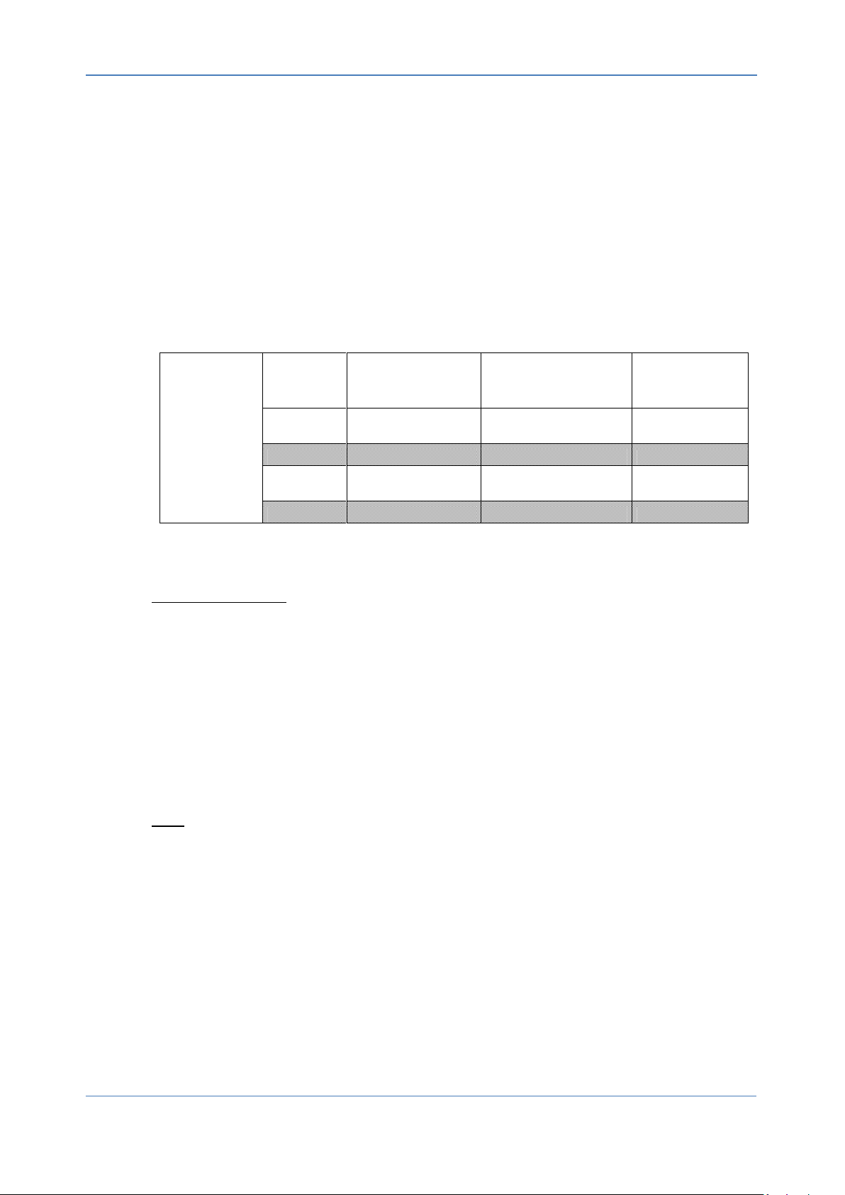
Drive Type
Input Current
Output current max
Output Power
08
4 A;
3,6 A<Input<4,75 A
Sinusoidal 3x3,5 A
800 W
11
6 A;
5,2 A<Input<6,2 A
Sinusoidal 3x5,7 A
1100 W
3. SPECIFICATIONS, FUNCTIONS AND PROTECTIONS
3.1. Mechanical and electrical specification
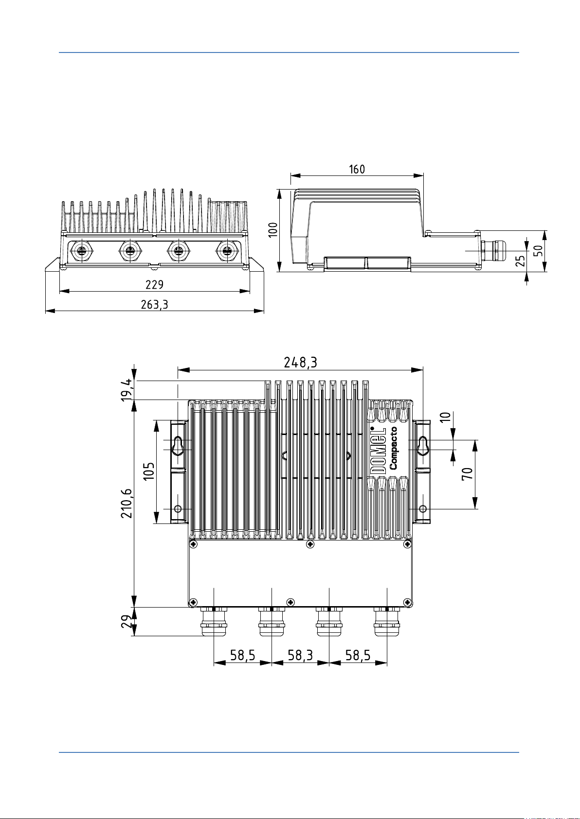
Dimensions………………………………..……………………….…263,3 x 259 x 100 mm
Weight………………………………………………………………………………..…..4,2 kg
Protection level…………………………………………………………………………….IP55
Power Supply: ………………………………...……..230 V/50-60 Hz; 200 V<UAC<265 V
Efficiency ………………………………….…….………………………………..…up to 95%
Power Factor (PF): ………………………………….………………………………..…..0,98
RPM min: ………………………………………………..………………...…20% of Nominal
RPM max: ………………………………………………………..………..………4.000 RPM
3.2. Functions
Relay Error function: Electronics are equipped with isolated Relay error function via relay
250VAC/5A, NC(4), COM(5) and NO(6).
Relay error function is activated by:
AC input under voltage protection,
Blocked rotor detection,
Phase failure / Phase loss detection,
Overheating detection,
Controller Error detection – Internal error of electronics,
Phase Overcurrent detection.
The error state is automatically reset by removal all error caused.
AN1: Analogue input 1 – Electronics can be controlled by external analogue input voltage 0-
10 or 10-0 VDC to terminals (7) and (8). Electronics controls speed linear from RPM min to
RPM max. Maximal or minimal speed is defined as input voltage 9,5V ± 3%.
To start control the motor speed by AN1, connect Stop/Start terminal pins (18 and 19) and
FIRE mode terminal pins (16 and 17) together.
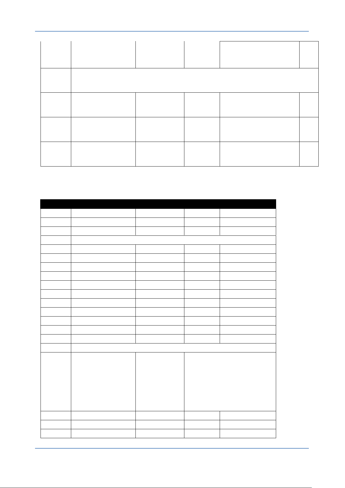
AN1 can be settable by holding registers 107, 108 and 109 (see Modbus parameters in
chapter 6). AN1Min parameter can be set to the desired minimum setpoint. AN1Max
parameter can be set to the desired maximum setpoint. AN1Min and AN1Max can be set from
0V to 10V. If AN1Max is smaller than AN1Min function is inverted (10V to 0V). By AN1Stop,
stop threshold voltage can be set. If AN1Stop is 0 threshold voltage is disabled and motor will
run with minimal settable RPM. By setting AN1Stop higher than 0 motor will not run up to
settable value.
5 Operating and installation Instructions V2.2, April 2015
Page 7
DOMEL EC – Controller Compacto
Picture 4
Picture 3
Picture 2
Picture 1
Example:
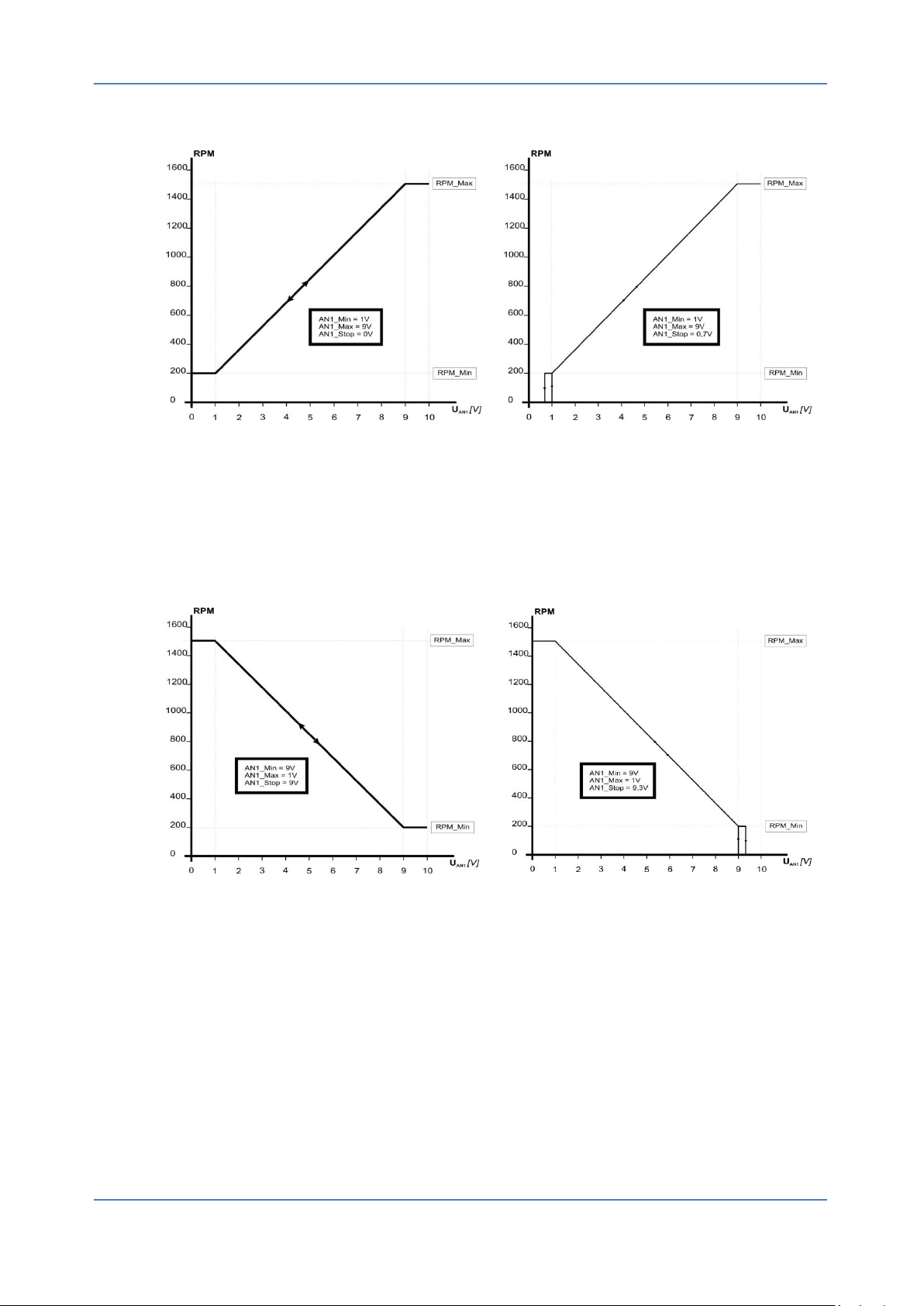
AN1min is set to 1V and AN1max is set to 9V. In the pictures above, controller works from
200RPM to 1500RPM. AN1 operates from 1V to 9V (AN1max > AN1min). AN1stop is set to
0V in picture 1, this means that AN1stop is disabled and motor will run with minimal RPM also
in case of AN1 and POT is 0V. In picture 2 AN1stop is set to 1V. this means that threshold
voltage is 1 and motor will not run below 1V.
AN1min is set to 9V and AN1max is set to 1V. In the pictures above, controller works from
200RPM to 1500RPM and AN1 operates inverted from 9V to 0V (AN1max < AN1min).
AN1stop is set to 10V in picture 3, this means that AN1stop is disabled and motor will run with
minimal RPM also in case of AN1 and POT is 10V. In picture 2 AN1stop is set to 9V. This
means that threshold voltage is 9V and motor will not run higher than 9V.
Hysteresis regulator will be preset in Domel on customer’s specifications.
Electrical parameters: Vin
=12V, Zin=10kΩ, Resolution 10-bit, tolerance AN1±5%
max
Important: Wrong polarity at input AN1 could cause serious damage on the controller.
V2.0, July 2014 Operating and installation Instructions 6
Page 8

EC – Controller Compacto DOMEL
Set RPM via potentiometer: Electronics can be controlled by external potentiometer (4k7 to
47kΩ) connected to terminals (8=gnd), (9=input) and (10=+5V). If the direction of rotary
potentiometer is incorrect, change the wires on terminal (8) and (10).
Electrical parameters: Three-wire, R
=4k7-47kΩ, Zin=10kΩ
pot
Power supply 5VDC/10mA: Electronics are equipped with 5VDC/10mA for power supply to
an external potentiometer. Power supplying other loads is not allowed. The 5 VDC supply is
galvanically isolated from the supply voltage, but has the same potential as the analogue and
digital inputs and outputs.
Electrical parameters: 5VDC +/- 5% (regulated); 10mA; Terminal number: 10.
Power supply 24VDC/40mA: Electronics are equipped with 24VDC/40mA power supply for
external sensor connected via AN2, or for small external fan for cooling controller. The 24
VDC supply is galvanically isolated from the supply voltage, but has the same potential as the
analogue and digital inputs and outputs.
Electrical parameters: 23VDC +/- 10% (not regulated); 50mA; Terminal number: 13, 16, 19.
AN2: Analogue input 2 – Electronics can be controlled by external analogue input signal AN2
for external sensor (temperature, CO2, smoke sensor, etc.).
Electrical parameters: Vin
=12V, Zin=10kΩ, Resolution 10-bit
max
Important: Wrong polarity at input AN2 can cause serious damage on the controller.
PID Control:
Electronics are equipped with internal PID regulator via AN2. The PID Control uses the value
on the AN1 as Set Point value.
For additional PID control parameter setting see chapter 6 (Controller configuration).
Speed output: Electronics are equipped with an Open Collector speed output signal for
speed monitoring.
Speed output mode could be set as:
Frequency output f=1Hz/1RPM @ 25mA, (1Hz means 1RPM, max frequency is
determined by the max RPM)
PWM output – D=0%↔RPM=0, D=100%↔RPM=100%,
PWM output – 10V / 1mA,
Current generator output 0-20 mA,
Current generator output 4-20 mA,
Voltage generator output 0-10 V/1 mA
Voltage generator output 2-10 V/1 mA
Voltage generator output 0-10 V/1 mA calculated regarding actual RPM with 5%
tolerance.
SO mode 9 (Chapter 6) is calculated by equation:
For additional parameter setting see chapter 6 (Controller configuration).
7 Operating and installation Instructions V2.2, April 2015
Page 9

DOMEL EC – Controller Compacto
Fire mode function: Electronics are equipped with Fire mode function. In this case
electronics runs as emergency controlled unit, (for example: extract the smoke from a burning
building), with disabled protections and functions.
In fire mode case:
Overheating protection - disable,
Under voltage protection - disable,
Start/Stop function – ignore,
Set RPM via AN1 or Potentiometer – ignore,
Set RPM via AN2 – ignore,
Phase overcurrent – disable,
Controller error detection - disable.
In Fire mode function electronics runs with Fire mode set parameters. These parameters
should be sets via Modbus registers. The function should be enabled by disconnect the
terminal pins (16) and (17). We recommended purpose switch. For disable the function
disconnect terminal pins (switch=ON).
Fire mode function can be also enabled via Modbus communication. For additional information
about activating fire function via Modbus, see the chapter 7.
Electrical parameters: Operating voltage = 24V, Zin=10kΩ
Note!
Fire mode function is useable only for protection in case of a burning
building, to extract the smoke from it. In normal condition the fire
mode function is not allow to be used. In this case Domel is not
responsible for damage to the controller caused by improper use.
Star/Stop function: Electronics are equipped with Start/Stop function. If the controller has all
conditions for running, the motor goes runs when the terminal pins (18) and (19), are
connected together.
Electrical parameters: Operating voltage = 24V, Zin=10kΩ
V2.0, July 2014 Operating and installation Instructions 8
Page 10
EC – Controller Compacto DOMEL
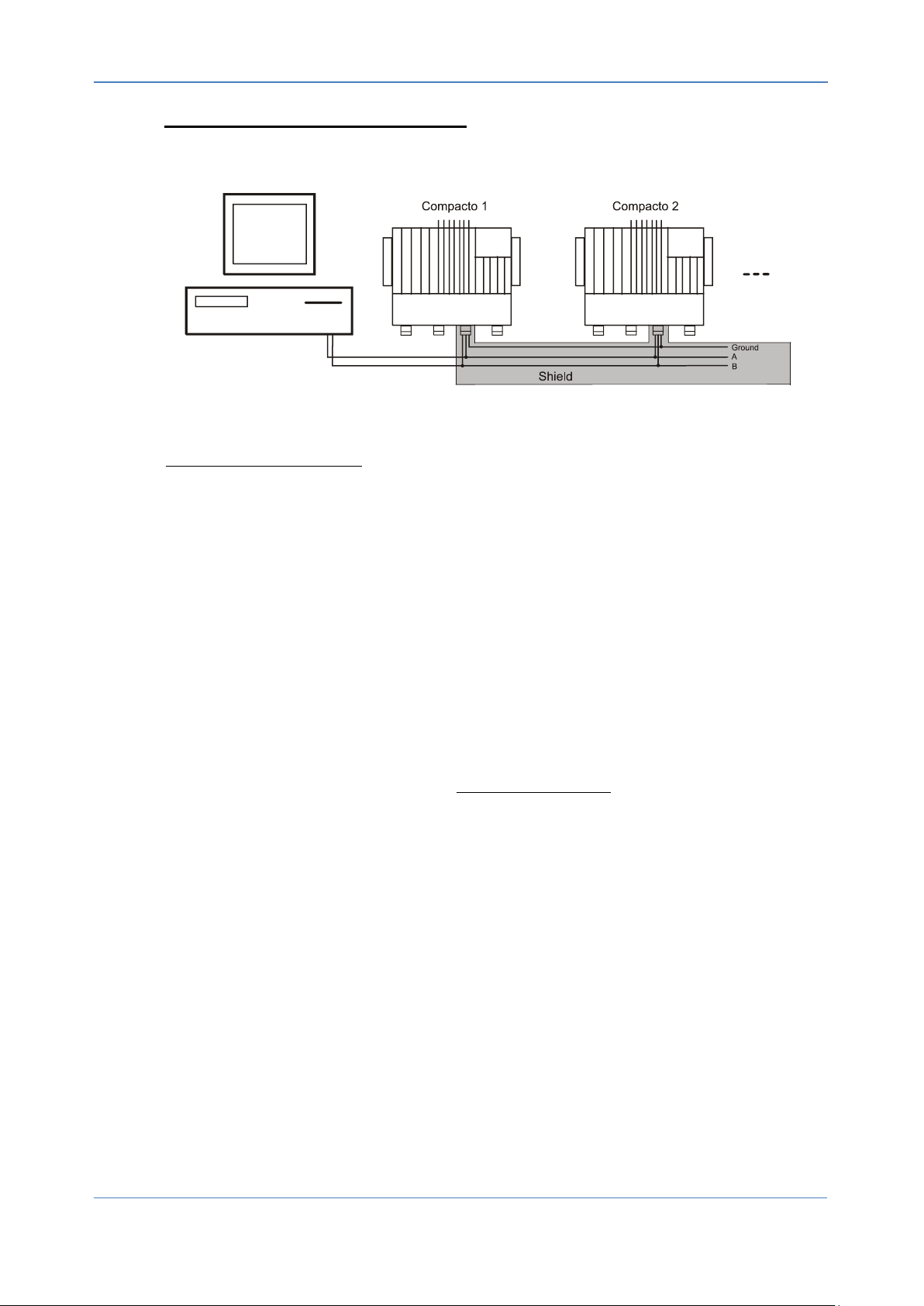
Modbus RTU 485 serial communication: Electronics are equipped with Modbus RTU 485
communication. To connect controllers into chain use only shielded cables.
Shielded cable for ground connection between controllers is necessary (terminal pin 14).
Speed control via MODBUS:
Parameter "Operation Mode" set to value 2 - Operation Mode = 2. The ON/OFF Switch
becomes inactive. To the Holding register at address 0 (Set_Point) write desired value of
speed in %.
For example:
Set_Point < 1000 (10,00 %) … Motor Stop
Set_Point = 1000 (10,00 %) … Motor Run at RPM_Min
1000 (10,00 %) < Set_Point <= 10000 (100,00 %) … Motor Runs at desired speed.
The motor speed is calculated by equation:
For additional information about Modbus parameters see chapter 5.
9 Operating and installation Instructions V2.2, April 2015
Page 11

DOMEL EC – Controller Compacto
3.3. Protections
Thermal protection: The electronics are equipped with reducing thermal protection. This
function is a temperature limiter which reduces the output power, when temperature on the
controller rises over 75°C. In this case relay error function set output error.
In the event that the temperature of controller is still rising (over 105°C) the controller stops the
motor. When the temperature controller falls below 75°C, the motor automatically restarts.
Thermal protection is disabled in fire mode state.
Under and over voltage: The electronics are equipped with under and over voltage
protection. Electronics shutdown when the main voltage is not in the required range. See
mechanical and electrical specification.
Blocked rotor protection: The electronics are equipped with blocked rotor protection when
the rotor of motor is blocked or it is impossible to rotate it. Electronics automatically retries 25
restarts, than a manual restart by disconnecting the power supply is required.
Motor phase fail / lose: The electronics are equipped with motor phase fail protection in
event that one of phase motors is damage or missing. In this case electronics stops the motor
immediately. Protection is disabled in fire mode state.
Phase overcurrent protection: The electronics are equipped with phase overcurrent
protection when current through motor increases up to 10A. In this event electronics stops the
motor immediately and tries to makes automatically restart.
Rotor failed acceleration: The electronics sre equipped with rotor failed acceleration
protection when the rotor is damaged or is hard to rotate. Electronics automatically retries 25
restarts for every 1second. If the 25th restart is still unsuccessful, then manual restart by
disconnecting the power supply is required.
Note!
Heating the controller over the maximal temperature is not allowed.
Above 105°C electronics stops the motor (not in fire mode state), and
restarts it again when the temperature of controller falls below 75°C.
However, if the controller is overheating and motor was shutdown,
disconnect power supply (safety switch) and wait at least 20 minutes
before you service them. In case of overheating of controller, the
metal parts of them are very hot and could cause serious damage to
your skin.
If controller starts reducing output power during running, this may be
reason of overheating. In this case add small 24V/40mA fan on
controller or ensure air flow through the ribs. Fan can be supplied by
power from controller (chapter 4.2. – wiring diagram). Overheating
problem appears in the case of installation of the controller in the
space without air flow.
V2.0, July 2014 Operating and installation Instructions 10
Page 12
EC – Controller Compacto DOMEL
Compacto
Length
max [m]
Power supply
-
Relay Fault
-
Set RPM via
voltage
-
Set RPM via
potentiometer
20
Speed Output
-
Fire mode
40
Start/Stop
40
Modbus
40
Motor
5
4. STRIPPING CONNECTING LEADS AND CONNECTING WITH TERMINALS
Use shield / armoured motor cable to comply with EMC emission specifications, and connect
this cable to both the decoupling plate and the motor metal.
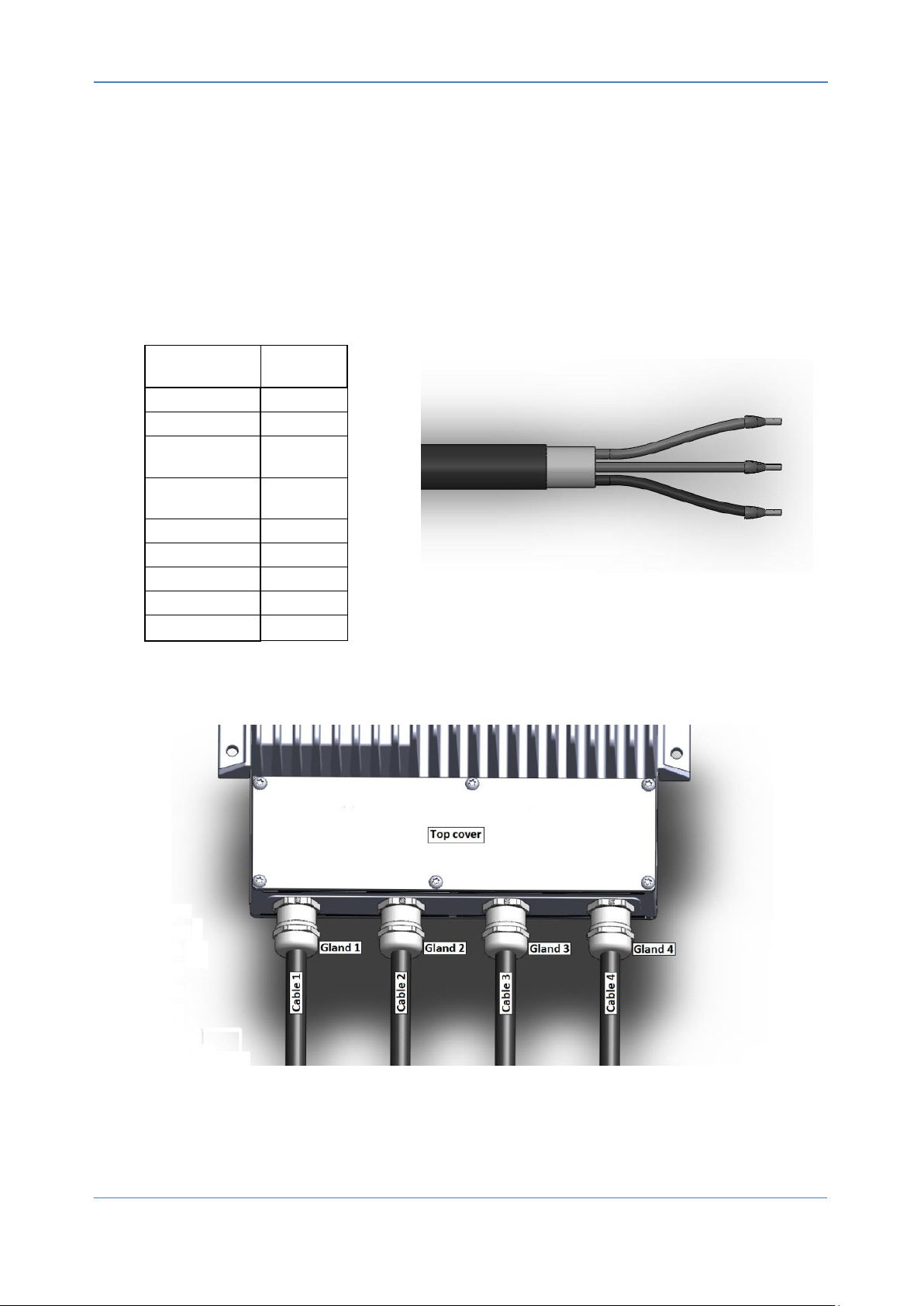
Use only hard wire or fibre copper wire with ferrule (Fig 1). For thickness of the wire, see the
table 2.
Keep motor cable as short as possible to reduce the noise level and leakage currents. To
reduce the operating problems, use a shielded cable. Max length of cables shown the table
below.
Table 1: Length of cables
Fig.1: Wire with ferrule
Fig.2: Description of cables
11 Operating and installation Instructions V2.2, April 2015
Page 13
DOMEL EC – Controller Compacto
4.1. Connection instructions:
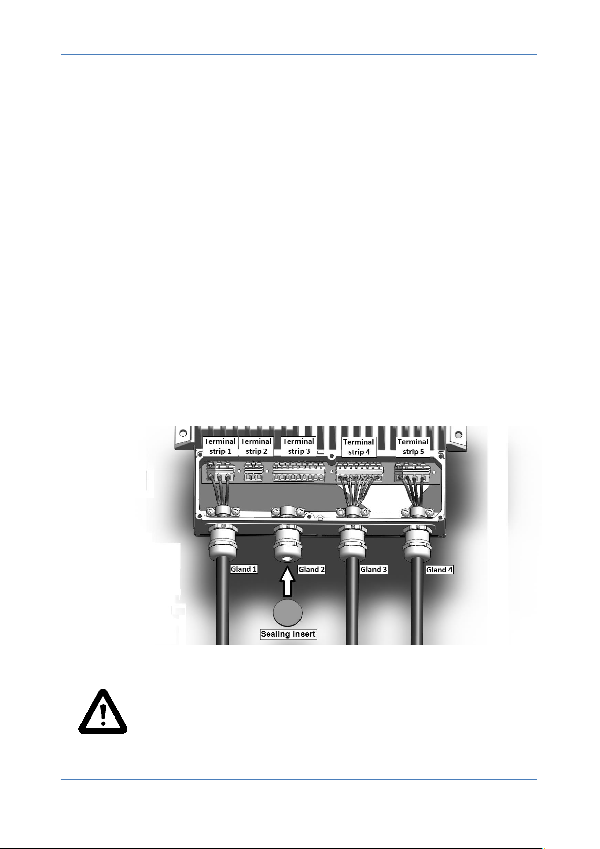
a) Remove the Top cover of the terminal strips (Fig.2).
b) Unscrew the nut of cable gland 4. Insert the motor cable through the gland and mount the
cable shield (Fig.3). Press the terminal strip 5 (Fig.3 and 4) and connect the motor wires to
the terminal strip 5. Tighten the nut of cable gland 4 for optimum IP protection.
c) Unscrew the nut of cable glands 3 and remove the sealing insert for sealing. Insert the control
cable (Cable3). Mount the cable by shield (Fig.3). Press the terminal strip 4 (Fig.3 and 4) and
connect control wires to the terminal strip 4. Tighten the cable gland 3 for optimum IP
protection.
d) Unscrew the nut of cable glands 2 and remove the sealing insert for sealing. Insert the control
cable (Cable2). Mount the cable (Fig.3). Press the terminal strip 3 (Fig.3 and 4) and connect
control wires to the terminal strip 3. Tighten the cable gland 2 for optimum IP protection.
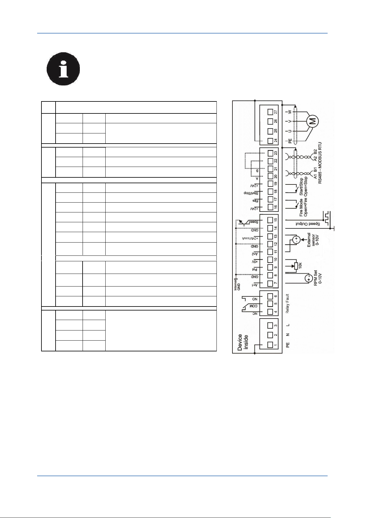
e) For power supply and Relay Fault function use one cable with 6 wires if Relay Fault is
needed. Unscrew the nut of cable glands 1. Press the terminal strip 1 (Fig.3 and 4) and
connect the Power wires to the terminal strip 1. Press the terminal strip 2 (Fig.3 and 4) and
connect the wires for Relay Fault. Tighten the cable gland 1 for optimum IP protection. Do not
lead Relay Fault cable through control cable glands 2 and 3. It could cause defect signals on
control wires.
f) If there is any blank cable gland, fill it with a sealing insert to seal.
g) Check all connections again and carefully replace the Top cover. Screw the top screw
h) Connect the Power supply voltage.
Fig.3: Example how to install cables, wires and install the sealing insert for sealing cable gland.
Warning!
Use cable with minimal 7mm thickness. All unused glands must be closed. Use
appropriate sealing insert or appropriate stopper if you not use cable. Top cover
must be tight with 1Nm of torque and all screws must be used. These actions must
be done to avoid humidity and water absorption inside controller. Water inside of
controller may cause serious damage on working.
V2.0, July 2014 Operating and installation Instructions 12
Page 14
EC – Controller Compacto DOMEL
Compacto
Drive Type
Nominal
voltage
Nominal
output
power
Safety fuse
Cable cross - section
mm2
AWG
Power supply
08
230V
800W
10A
2,0-2,5
13
User control
0,5 - 2,5
20 - 13
Power supply
11
230V
1100W
10A
2,0-2,5
13
User control
0,5 - 2,5
20 - 13
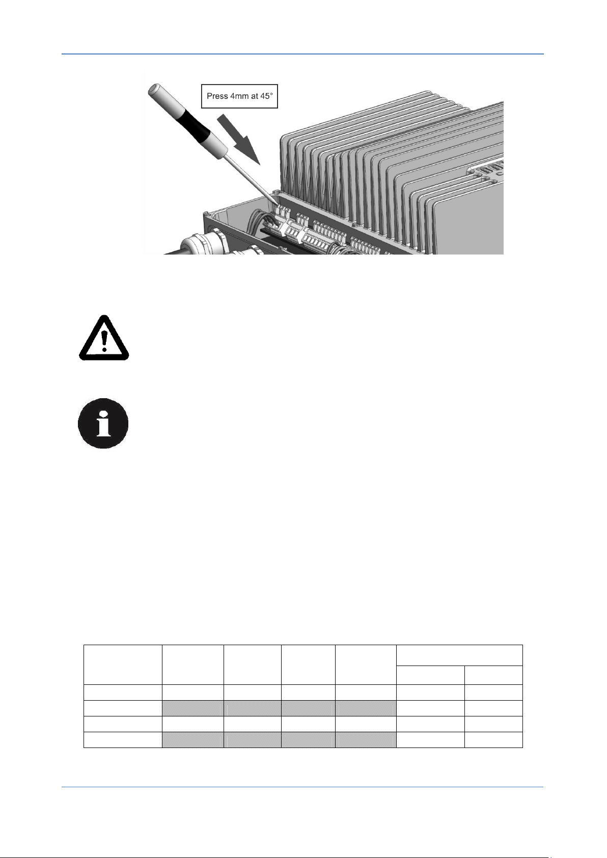
Fig.4: How to operate correctly with terminal strips
Warning!
Press only 0.5kg max, 4mm deep at angle 45° with 3mm slot screwdriver.
Damaged terminal strips could cause fatal damage on the Controller and could
cause fatal injury from electric shock.
Note!
It is the responsibility of the user or installer to ensure correct
grounding and protection in accordance with national and local
standards.
4.2. Connecting the electrical system
Check whether the data on the type plate agrees with the connection data.
Before connecting the device, ensure that the supply voltage matches the operating voltage of
the device.
Only use cables that are configured for the current according to the specification on the type
plate.
4.2.1. Mains supply connection and fuse protection
13 Operating and installation Instructions V2.2, April 2015
Table 2: Thickness of wire
Page 15
DOMEL EC – Controller Compacto
Terminal
number
Description
Mains supply
PE
1
PE connection
N
2
Supply voltage
L
3
Relay Fault
NC
4
Normally close
COM
5
Common connection; Contact rating 250V / 5A
NO
6
Normally open
Control
AN1
7
Analogue Input 1; Set value 0-10 V or 10-0 V; R ≥ 1 kΩ
GND
8, 12, 14
I/O ground
Pot
9
Potentiometer output (3 wires)
+5V
10
+5 V ± 5 % / 10 mA for potentiometer
AN2
11
Analogue Input 2 for external sensor (PID Control)
+24V
13, 16,
19
+24 V ± 10% DC / Imax 40 mA
Speed
15
Digital output; NPN open collector output
Fire
17
Digital input; FIRE mode: Enabling function – open pin;
Disabling Bridge to +24 V
Start/Stop
18
Digital input; Start/Stop mode: Disabling function – open
pin; Enabling Bridge to +24 V
A
20, 22
Bus connection RS485 – A; MODBUS RTU
B
21, 23
Bus connection RS485 – B; MODBUS RTU
Motor
PE
24
Motor connection
U
25
V
26 w 27
Connect the device only to the circuits that can be switched off using an allpole disconnecting switch.
V2.0, July 2014 Operating and installation Instructions 14
Page 16
EC – Controller Compacto DOMEL
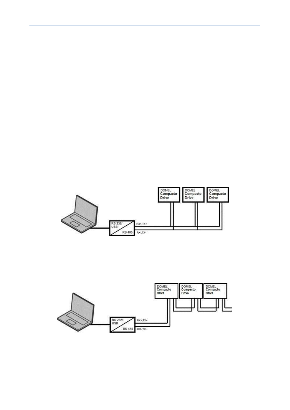
5. MODBUS RTU
The MODBUS RTU protocol is based on the built-in RS-485 (EIA-485) interface. RS-485 is a two-wire
bus-interface that allows multi-drop network topology i.e. nodes can be connected as a bus (daisy
chain), or via drop cables from a common trunk line.
Domel’s Compacto drives uses the two-wire system where the communication between master and
slave is half-duplex, i.e. it cannot transmit and receive at the same time. Each signal uses one twistedpair line — two wires twisted around themselves. The signal on one wire is ideally the exact opposite
of the signal on the second wire. Since RS-485 is a multipoint communication system, all devices are
connected to the single twisted-pair cable.
The Modbus RTU uses master/slave architecture, where each slave device has its unique address
and responds only to packets addressed to this device. The packets are generated by the master
(Controller), which periodically polls all connected slave devices. Data travels over the single line in
both directions.
One or more EC drives can be connected to a control (or master) using the RS-485 standardized
interface. Maximal number of Compacto EC Drives connected to the network is 32. If more than one
frequency converter is connected to a master, use parallel connections. Terminal 14 is connected to
the signal TX+, RX+, while terminal 15 is connected to the signal TX-,RX-.
Parallel connections
“Daisy chain” connection
15 Operating and installation Instructions V2.2, April 2015
Page 17

DOMEL EC – Controller Compacto
Default Configuration (set by Domel):
MODBUS address: 1
Baud Rate: 19200
START Bit: 1
STOP Bit: 1
Parity: NONE
Supported MODBUS commands:
0x01: Read Coils
0x02: Read Input
0x03: Read Holding Registers
0x04: Read Input Register
0x05: Write Single Coil
0x06: Write Single Holding Register
To connect PC and DOMEL Compacto Drive over serial line (MODBUS) RS-232/USB to RS-485
Converter is needed. We recommend ADAM-4561 converter. To attach the ADAM-4561 to a PC, you
do not need to power down your PC. The power for the ADAM-4561 converter is derived from the USB
port, so there are no power adapters to deal with.
The ADAM-4561 device driver can be used in combination with Windows 2000/XP/Vista/7 (32 & 64bit).
V2.0, July 2014 Operating and installation Instructions 16
Page 18
EC – Controller Compacto DOMEL
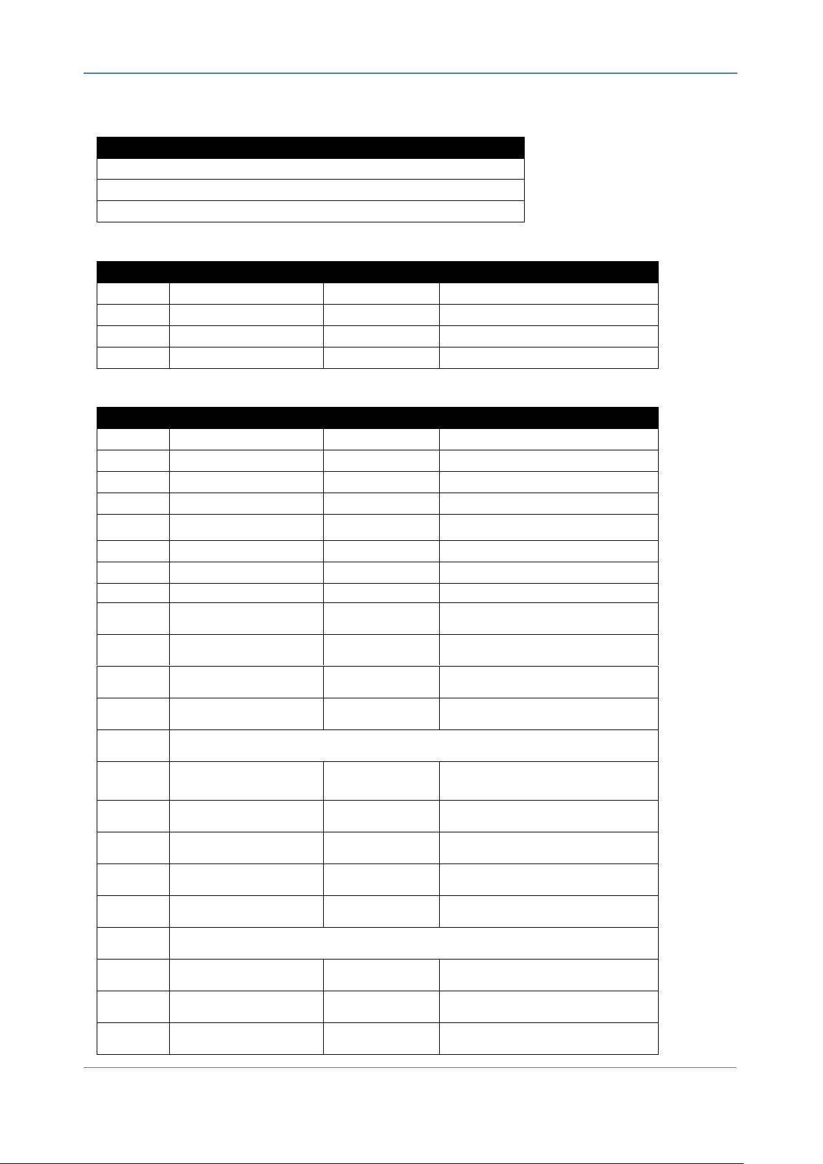
Configuration
MODBUS RTU: 19200-8-N-1
Slave addr: 0x1 (default settable by MB_ADR:0007)
(Strikethrough text indicates partially implemented or unimplemented function)
Coils
Address
Function
Range
Description
0
Motor ON/OFF
0-1
Indication, 1=ON, 0=OFF
1
Reset Controller
0-1
1=Reset controller
2
Fire active
0-1
1=Fire mode active
Discrete status bits (inputs)
Address
Function
Range
Description
0
Under Voltage
0-1
1=Voltage too low to run
1
Over Voltage
0-1
1=Voltage too high to run
2
IGBT Overcurrent
0-1
1=Overcurrent protection tripped
3
Hot
0-1
1=Temperature protection active, power
reduced
4
Phase Loss
0-1
1=Phase or motor sync loss
5
PFC Overcurrent
0-1
1=PFC FET protection tripped
6
Parameters CRC
0-1
1=Parameter checksum failed (TBD)
7
Circuit Fault
0-1
1=There was an error detected during
circuit internal check
8
Motor Fault
0-1
1=Motor does not behave as expected
9
Too Hot
0-1
1=Converter too hot to operate
10
I2R IGBT Fault
0-1
1=Software IGBT protection triggered
11 - 13
RESERVED
14
Restart Fault
0-1
1=Fault condition repeated several times
in a short time. Converter power should be
power cycled or reset.
15
On Fire
0-1
1=Fire input was activated
16
Run Active
0-1
1=Run input was activated
17
Relay Active
0-1
1=Relay output is active
18
Waiting To Stop
0-1
1=Motor should be stopped, but is still
spinning
19 – 23
RESERVED
24
RpmReg
0-1
Speed regulator active
25
PowerReg
0-1
Power limit regulator active
26
IacReg
0-1
Line current regulator active
6. MODBUS PARAMETERS
17 Operating and installation Instructions V2.2, April 2015
Page 19
DOMEL EC – Controller Compacto
27
OvermodReg
0-1
Over modulation reached. Converter can
no longer supply the voltage required by
motor.
28
RegenReg
0-1
Motor is in regeneration. Speed increased
to prevent DC link over voltage
29
IphaseReg
0-1
RMS motor phase current limit reached
30
SyncReg
0-1
Motor is still in Synchronous mode
31
RESERVED
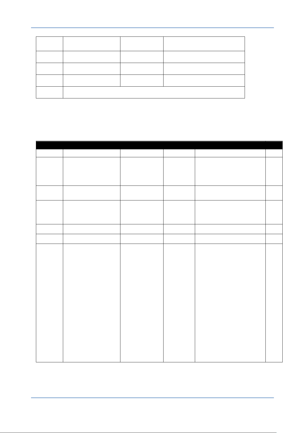
ACCESS LEVEL:
0 – read only
1 – basic user settings
2 – service settings
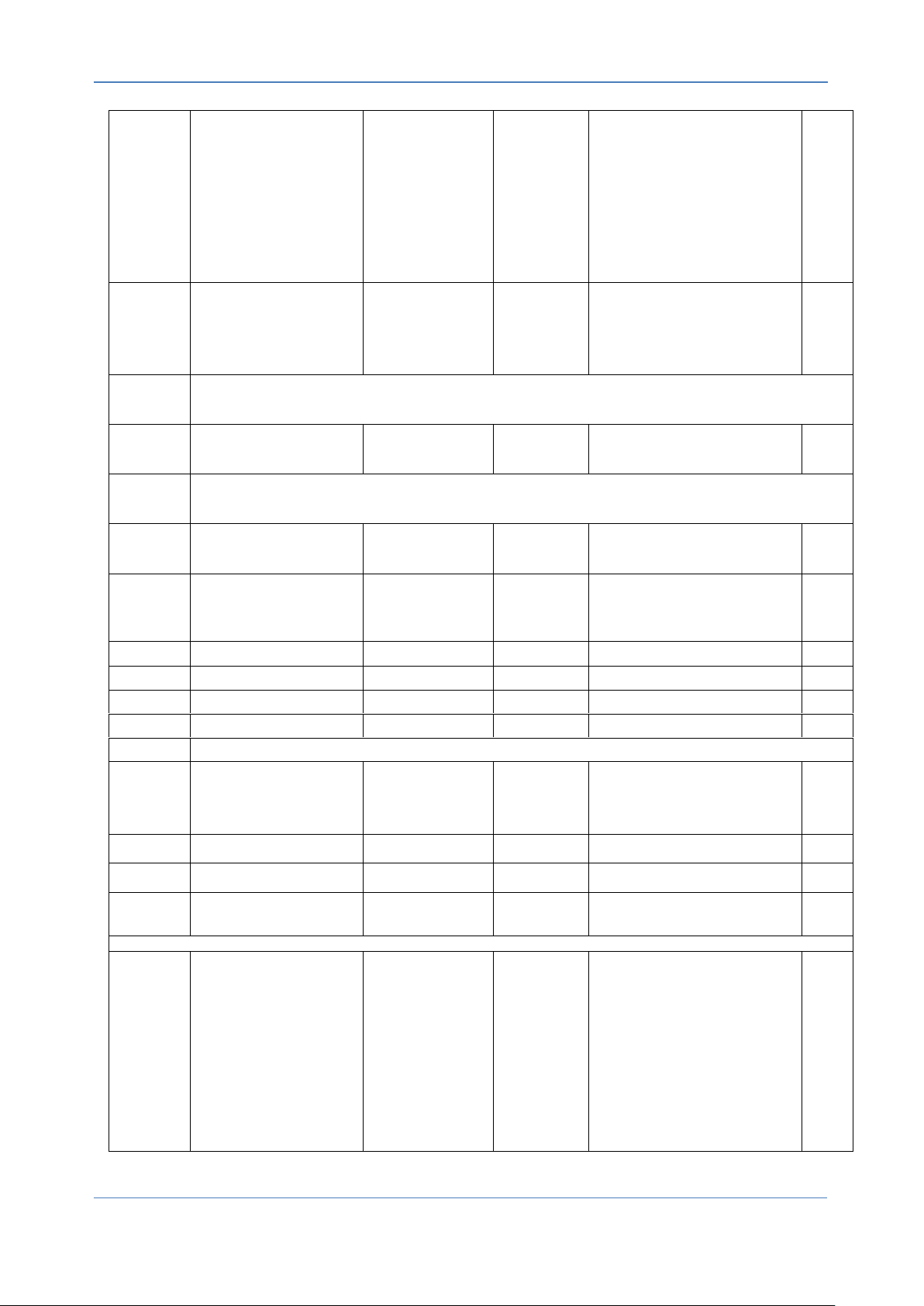
Holding Registers
Address
Function
Range
Resolution
Description
LEVEL
0
Set point
0..10000
0,01%
Performance set point for speed
depends on operation mode.
1
1
Direction
0..65535
1
Motor direction:
0: clockwise rotation.
>0: anti-clockwise rotation
2
2
Maximum Speed
MinRPM..
MaxRPM[level+1]
1
Max rpm allowed in normal
operation. External control will use
this as set point maximum. Value
from level above current is used as
Max.
1
3
Fire Speed
0.67*RPM_Max to
RPM_Max
1
RPM when fire mode is active
(2/3*RPM_Max to RPM_Max)
2
4
Minimal Speed
200 RPM to Max
RPM
1
Minimal allowed speed
1
5
Password
0..32767
0: level 0, all settings locked (default
password for level 1)
1: password for current level will be
disabled with 10020
10000: store values to EEPROM at
current level (will override lower
levels)
10001: restore values from
EEPROM (last saved values)
10002: restore default values from
one level above current
10020: set previous value as
password
(will not be accepted if desired
password matches 10000..11000 or
level is <1)
See 1: for how to disable password
When level is changed, stored
values for the level will be loaded
1
V2.0, July 2014 Operating and installation Instructions 18
Page 20
EC – Controller Compacto DOMEL
6
Operation Mode
0: AN1 or POT Speed (default)
2: MODBUS Speed (run switch
inactive)
9: PIDRef (addr 16)-AN2 Speed
regulator (heat)
10: AN2- PIDRef (addr 16) Speed
regulator (cool)
11: AN1-AN2 Speed regulator (heat)
12: AN2-AN1 Speed regulator (cool)
-1:FIRE Mode (>when in access
level >=2 »motor will run at »Fire
Speed«)
1
7
Modbus Address
1..247
1
Set Modbus address:
Write 10000 to Password to save.
Restore by writing to broadcast
address (0) (in case you forgot
address)
1
8
RESERVED
9
Fire Limit
Fixed fire speed (settable by reg. 3 if
0)
2
10
RegIndex
11
Kp
100..32000
0.001
(0.1 min, 32
max)
External controller proportional gain
1
12
Ti
0..32000
0.1s
(3200s max)
External controller Integration time
0: no integration
1
13
Td
External controller diff. time
1
14
PIDMin
0..10000
0.01%
PID regulator minimum output
1
15
PIDMax
0..10000
0.01%
PID regulator maximum output
1
16
PIDRef
0..1000
1
PID regulator reference selection
1
20 - 27
FACTORY SETTINGS
28
Resonance1
0..10000
1
Rpm where 1st resonance occurs
(set 0 to ignore).
Converter will avoid this rpm.
Avoidance will only work if rpm
regulator is active.
1
29
Resonance2
0..10000
1
Rpm where 2nd resonance occurs
(set 0 to ignore)…
1
30
Resonance3
0..10000
1
Rpm where 3rd resonance occurs
(set 0 to ignore)…
1
31
Resonance Width
2..20%
1
Width of resonance avoidance band.
Example: R28=1000, R31=20
Converter will avoid 900-1100 rpm.
1
Controller configuration
100
Speed output mode
0..8
SO output Mode:
0: disabled (input),
1: FREQ(25mA),
2: FREQ(10V, 1mA),
3: PWM(25mA),
4: PWM(10V,1mA)
5: 0..20mA,
6: 0..10V(1mA),
7: 4..20mA,
8: 2..10V(1mA),
9: 0..10V (1mA) – calculated
regarding actual RPM. See chapter
3.2.
>9: reserved
1
19 Operating and installation Instructions V2.2, April 2015
Page 21
DOMEL EC – Controller Compacto
101
SO output signal
-10000..2
0.01%
<1: Manual output value
(-10000=100%)
1: Motor RPM
2: Set Point
>2: reserved
1
102 - 106
RESERVED
107
AN1Max
0..1000
0.01V
Voltage for maximum setpoint.
Transfer function is inverted if
AN1Max < AN1Min.
1
108
AN1Min
0..1000
0.01V
Voltage for minimum setpoint
1
109
AN1Stop
0..1000
0.01V
0: disable stop
AN1Stop >0: Stop threshold voltage.
1
Input Registers
Address
Function
Range
Resolution
Description
0
HW Version
1 Hardware version
1
FW Version 1
Firmware version
2..3
RESERVED
4
Speed
0..32767
1
RPM 5
Controller temperature
-50..150
0.01
°C 6
UDC 0.1
DC Bus voltage in V
7
Stator IRMS
0.001
RMS Stator current in A
8
Power 0.1
W
9
Analogue1
-300..2000
0.01V
Analogue input 1 voltage
10
Analogue2
-300..2000
0.01V
Analogue input 2 voltage
11
Analogue POT
-300..2000
0.01V
Analogue POT voltage
12
SO voltage
-300..2000
0.01V
SO output voltage
13
SO current
-300..3300
0.01mA
SO output current
14
IAC 0.001
Line RMS current in A
15 - 18
RESERVED
19
Error Code
0..7, -1
Red LED error codes (priority in the order
below):
7 = motor failed to start repeatedly
6 = under or overvoltage
5 = motor misconnected/faulty
4 = internal frequency converter fault
3 = temperature protection active
2 = active overcurrent protection
1 = slow blink = standby
-1 = fast blink (fire activated)
0 = always on (operating normally)
20
Fire Minutes
Minutes under fire mode
21
Fire Days
Days under fire mode
22
Fire Cycles
Fire activated counter
V2.0, July 2014 Operating and installation Instructions 20
Page 22

EC – Controller Compacto DOMEL
23
Op Minutes
Minutes of operation
24
Op Days
Days of operation
(RPM>0, no error)
21 Operating and installation Instructions V2.2, April 2015
Page 23
DOMEL EC – Controller Compacto
COMPACTO Errors/W arni ngs
Re lay e rror
Mes sa ge
Modb us e rror
Wa rni ng
Re start R equi red
Man ual Res tart *
Re start R equi red
Auto Res tart
Lim its/ Rema rks
1 AC in put un dervol tage X X X 60V < UAC < 200V
2 AC in put ove rvol tage X X UAC > 265V
3 Bl ocked rotor X X X Man ual res tart req uire d afte r 25 au tomati cal ly res tarts
4 Fa il ed roto r accel era tion X X Auto re sta rt afte r 1s; Afte r 25 auto mati call y res tarts, manu al resta rt requ ired
5 Pha se fai lure /pha se los s X X X Pha se dama ge/m is sin g moto r ph ase
6 Overhe athi ng wi ndi ngs X No o verh eati ng wi ndi ngs prote ctio n
X Tem p. el ectroni cs > 80°C. redu cting outpu t powe r
Tem p. el ectroni cs > 105°C. Motor s hutdo wn:
De crea si ng Te mp. of ele ctroni cs be low 75°C. Autom atl ical ly re start
8
Control le r error (i ntern al
error o f el ectroni cs)
X X X
X X X Motor p has e curre nt > 10A
X X X Conta ct motor p has e to earth (PE)
10 Fire mode acti vated X Fi re mod e fun ction acti vate d – s ome p rotecti on a re di sa ble d
11 PFC Overcurren t X X X prote ction tripp ed
12 Motor fa ult X X X som ethi ng i s wron g wi th motor
13 Run a ctive X In dica tor
14 Rel ay a ctive X In dica tor
15 Wai thin g to s top X In dica tor - Te lls whe n mo tor stop
*Disconnect controller from Power distribution network for 5 min
X
9
Pha se overcurren t
7
Overhe ati ng el ectron ics
X
X
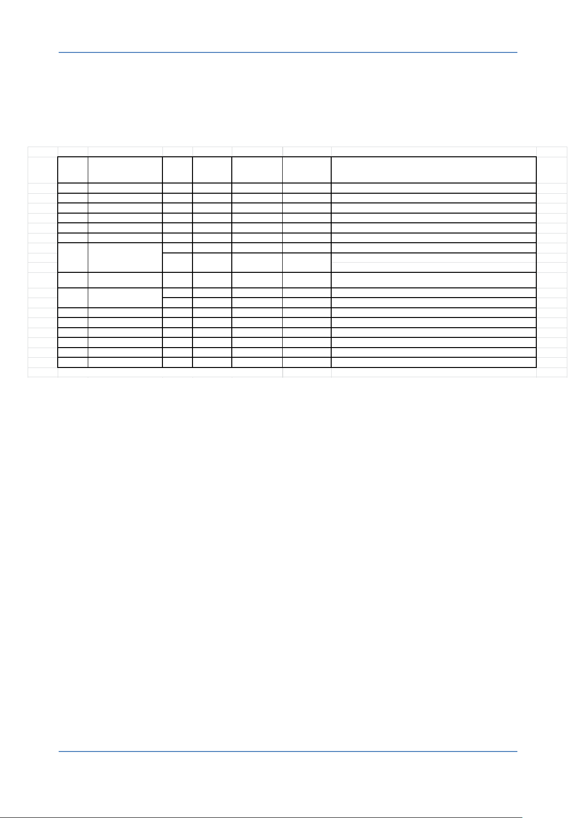
7. TROUBLESHOOTING
The power supply must be disconnected for at least 5 minutes before the EC controller is
opened. Otherwise the unit may contain residual current capable of causing serious injury.
V2.0, July 2014 Operating and installation Instructions 22
 Loading...