

Page 1
Always Connected. Always Covered.
Door/Window Sensor
DMDP1
User Manual
Page 2

Preface
As this is the full User Manual, a working knowledge of Z-Wave automa-
tion terminology and concepts will be assumed. If you are a beginner user,
please visit www.domeha.com for instructions. This manual will provide
in-depth technical information about the Door/Window Sensor, especially in
regards to its compliance to the Z-Wave standard (such as compatible Com-
mand Classes, Association Group capabilities, special features, and other
information) that will help you maximize the utility of this product in your
system.
Door/Window Sensor Advanced User Manual
Preface
Page 2
Page 3

Table of Contents
Preface ........................................................................................................2
Description & Features ................................................................................4
Specifications .............................................................................................. 5
Physical Characteristics ..............................................................................6
Inclusion & Exclusion ...................................................................................7
Physical Installation ....................................................................................9
LED Behavior .............................................................................................11
Button Behavior .........................................................................................12
Compatible Command Classes..................................................................13
“Configuration” Command Class Parameters ............................................16
Troubleshooting ........................................................................................19
Warranty & Support....................................................................................20
Door/Window Sensor Advanced User Manual
Table of Contents
Page 3
Page 4
Description & Features
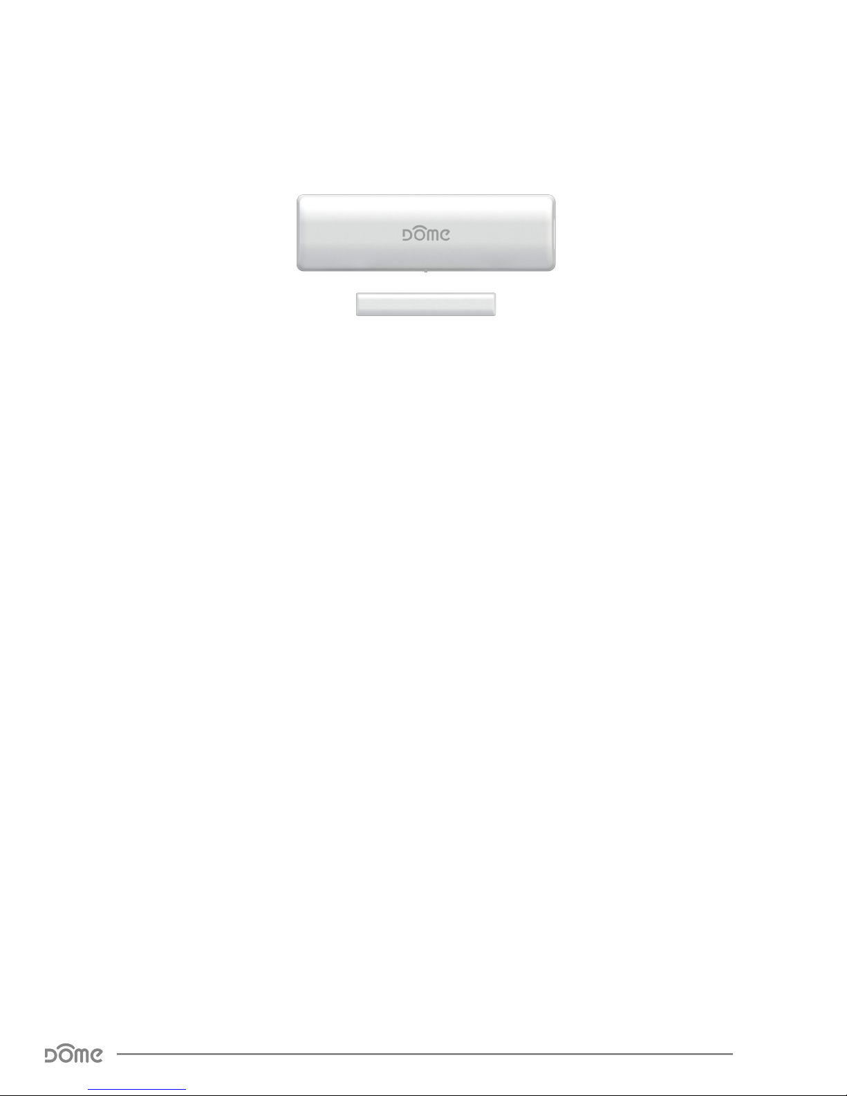
The Dome Door/Window Sensor is a battery powered security-enabled*
Z-Wave Plus magnetic reed switch that can monitor the status of doors,
windows, and anything else that opens and closes. It can also report ambient temperature levels. The Door/Window Sensor consists of two parts the “sensor,” and the “magnet.” The sensor has a “reed switch” inside, which
is sensitive to the magnet’s presence when aligned properly and within the
defined distance. When the sensor and magnet are brought together or
pulled apart, the sensor will report its open/close status to its Z-Wave controller, and the encrypted wireless communication* ensures that user data
remains secure. Because many manufacturers use Z-Wave to communicate,
the Door/Window Sensor can interact with different products of different
categories.
Key Features:
» Z-Wave Plus Certified
» S0 Security-Enabled*
» Built-In Temperature Sensor
» Up to 250’ range
» Ten-Year Battery Life
» LED Signal Strength Indication
» 1.25” Max distance between sensor & magnet
» Ultra-Narrow (1/4”) Magnet for Placement Between Door and Casing
» Monitor doors, windows, medicine cabinets, drawers, garage doors,
and many other openings
*A security-enabled Z-Wave Plus controller is required to use all features of the Door/Window Sensor.
Door/Window Sensor Advanced User Manual
Description & Features
Page 4
Page 5
Thank you for your purchase of the DOME
Window/Door sensor, a device which allows you
to monitor the activity of windows, doors, garages
and more.
QR Code
Underneath
LED
Indicator
Follow the instructions for your Z-Wave certified
Controller to include the Window/Door sensor.
When prompted by the Controller:
1. Remove the cover of the Window/Door sensor.
2. Remove the Battery Tab.
3. Press the Connect button quickly 3 times in
a row.
A red LED will flash five times indicating inclusion.
Set Up:
Note: Door/Window sensor should be within 10 feet of the Controller to include
properly. After inclusion, the device can then be moved to any desired location.
Follow the instructions for your Z-Wave certified
Controller to exclude the Window/Door sensor.
When prompted by the Controller:
1. Remove cover of the Window/Door sensor.
2. Press the Connect button quickly 3 times in
a row.
Excluding/Disconnecting from the
Z-Wave Network:
A red LED will flash five times indicating
exclusion/disconnection.
Open/Close
Button
Door Sensor
Magnet
Non-Dome System
Set Up:
DOME System
1. Pull up the DOME App on your Smart Phone.
2. Press the Menu button ( ), then select the
option “Add New Device.” The App will then take
you step-by-step connecting the Window/Door
sensor to the system.
CR14520
BATTERY
BATTERY
TAB
Connect
Button
Remove
Plastic Tab
LED
Inside of Door sensor
Open/Close
Button
Note: Requires the DOME Hub or any other Z-Wave certified Hub for use.
20
19
18
17
16
15
14
13
12
11
10
9
8
7
6
5
4
3
Specications
Technical Specications
Radio protocol
Power supply
Standby current
Working current
Operating temperature
Radio frequency
Range
Dimensions (L x W x H)
Table 1 - Technical Specications
Z-Wave(500 series)
Single ER14505 (AA) 3.6V battery
7uA
35mA
32 - 104 °F (0 - 40 °C)
908.4 MHz US
Up to 250’ depending on environment
Sensor: 2.9” x 0.85” x 0.87” (75 x 21 x 22 mm)
Magnet: 1.6” x 0.25” x 0.5” (40 x 6.35 x 12
mm)
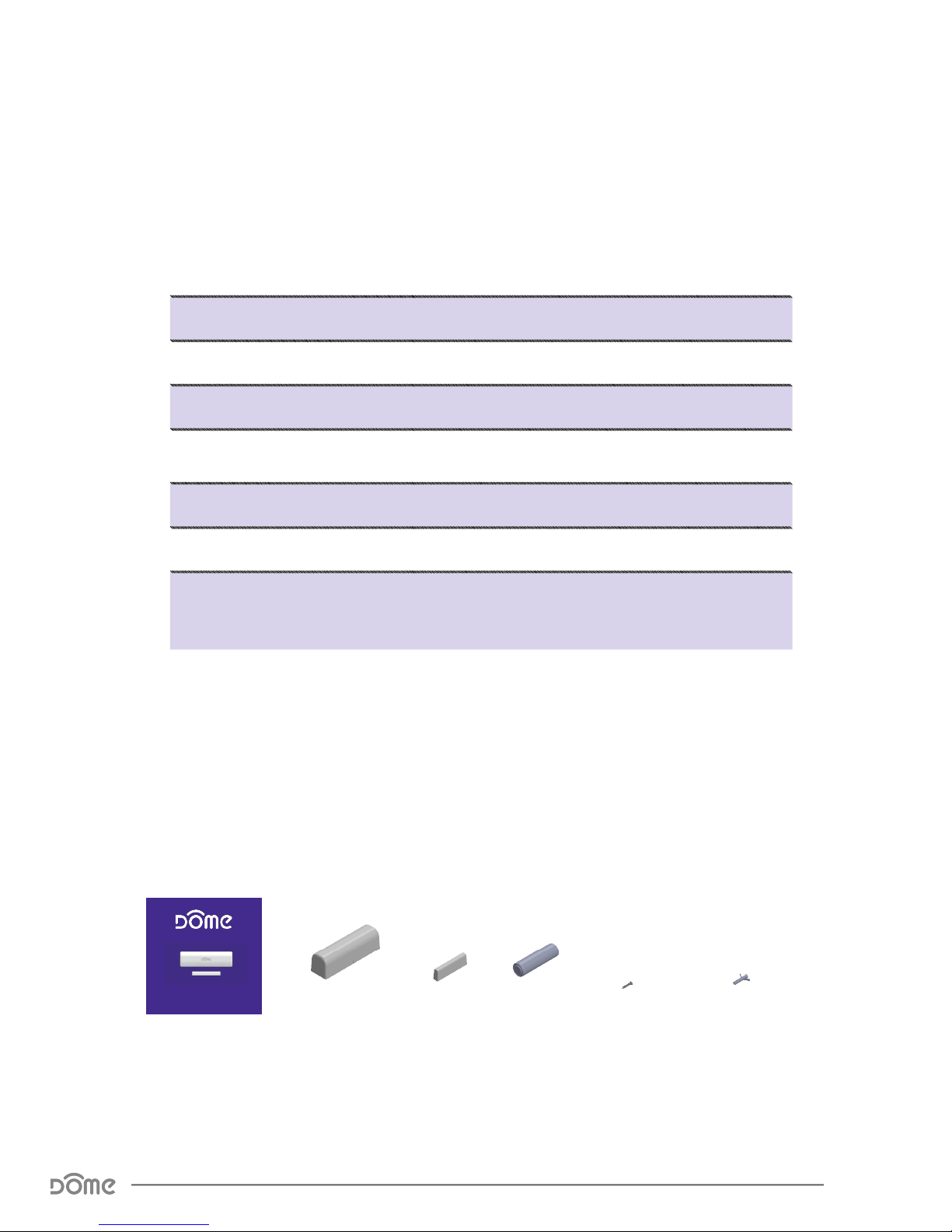
Package Contents:
WINDOW/DOOR SENSOR
User Manual Sensor Magnet 4x Screws
Door/Window Sensor Advanced User Manual
Specications
Battery
4x Wall Anchors
Page 5
Page 6
Physical Characteristics
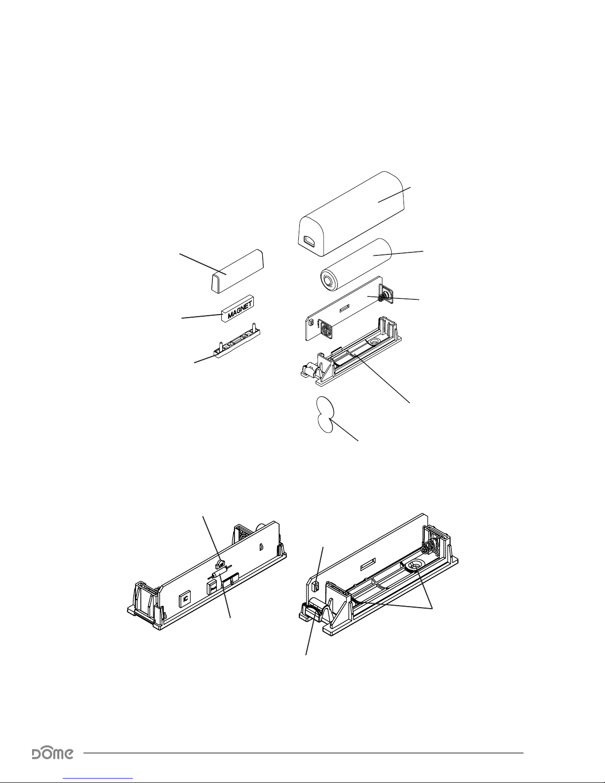
The names used in Figures 1 & 2 will be used throughout this manual. Please
refer to this page as needed.
Sensor Cover
Magnet Cover
Magnet
Magnet Base
Battery
Circuitboard Assembly
Sensor Base
Battery Tab
Figure 1 - Exploded View
LED Indicator
Reed Switch
Figure 2 - Main Parts of the Door/Window Sensor
Door/Window Sensor Advanced User Manual
Physical Characteristics
Button
Screw Holes
Sensor Cover Release Button
Page 6
Page 7

Inclusion & Exclusion
Inclusion (Add to System)—New Installation
1. For proper inclusion, bring the Door/Window Sensor to the final location where
it will be used*.
2. Follow the instructions for your Z-Wave controller to enter inclusion mode.
3. Remove the Battery Tab protruding from the Battery Tab Slit.
4. The device will automatically enter inclusion mode for two minutes and the
LED Indicator will alternate between green and red.
Upon successful inclusion the LED Indicator will flash green three times then stop
blinking.
Inclusion (Add to System) —Re-Installation
1. For proper inclusion, bring the Door/Window Sensorto the final location where
it will be used*.
2. Follow the instructions for your Z-Wave controller to enter inclusion mode.
3. Remove the Sensor Cover and the LED Indicator will start blinking yellow.
4. Press the Button quickly 3 times in a row.
5. The device will enter inclusion mode for two minutes and the LED Indicator will
alternate between green and red.
After successful inclusion, the LED Indicator will flash green three times then
blink red until the cover is replaced.
Exclusion (Remove from System)
Follow the instructions for your Z-Wave Certified Controller to enter exclusion
mode. When prompted by the controller:
1. Remove the SENSOR COVER and the LED Indicator will start blinking red.
2. Press the Button quickly 3 times in a row.
The LED Indicator will flash green three times indicating exclusion/disconnection
and will then continue flashing red (indicating tamper) until the cover is replaced.
*For non Z-Wave Plus networks, please consult the owner’s manual for your primary controller to determine the best method and location
for adding the Door/Window Sensor to your Z-Wave network.
Door/Window Sensor Advanced User Manual
Inclusion & Exclusion
Page 7
Page 8

Resetting the Door/Window Sensor
If needed, the Door/Window Sensor can be reset locally by following these
steps. Only do this if your Z-Wave controller is missing or otherwise un-
reachable. Beware that resetting your device will disconnect it from the
system:
1. Remove the Sensor Cover and confirm that your Door/Window Sensor is
powered up.
2. Wait for 5 seconds.
3. Move the Magnet and Sensor Base in and out of the closed position 6
times.
4. The LED Indicator will light up red for five seconds when reset successfully.
The Door/Window Sensor’s memory will be erased to factory settings.
Waking Up The Door/Window Sensor
Because the Door/Window Sensor is a battery powered device, it wakes up on
regular intervals to give battery and other status updates to the controller, as
well as to accept configuration settings from the controller. This helps to extend
the battery life. The Sensor Cover holds down the Button when installed, and
the device can be forced to wake up to submit reports or accept new settings
immediately by simply removing the Sensor Cover and then replacing it after. If
the device is already included in a system, the LED Indicator will flash Red until
the cover is closed.
Door/Window Sensor Advanced User Manual
Inclusion & Exclusion
Page 8
Page 9
Physical Installation
The Door/Window Sensor can be secured with the pre-applied double stick
tape or the provided hardware. The device should already be included in
your Z-Wave system before continuing further.
Pre-Installation Checklist
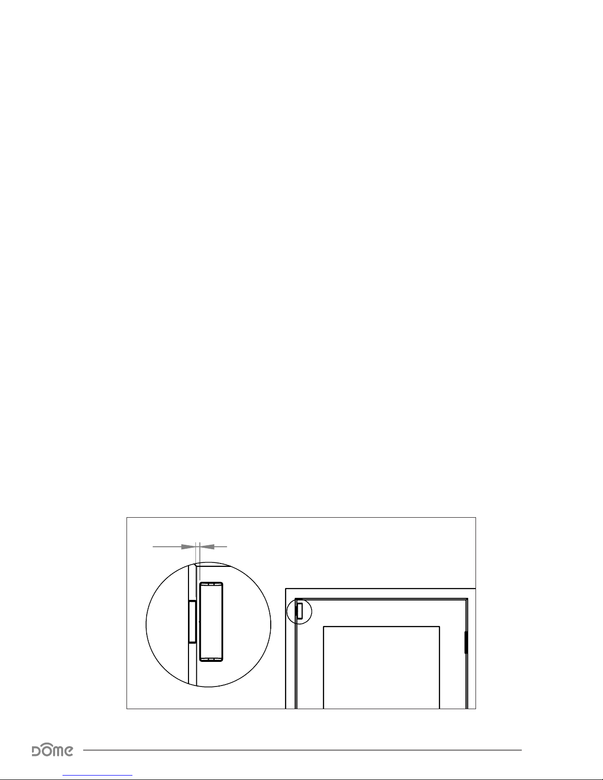
9 The Magnet Assembly and Sensor Assembly should be less than
1-1/4” apart when closed (Figure 3.)
9 Hold the Magnet Assembly and Sensor Assembly in place by hand
where you wish to install them, move them in and out of the closed
position, and make sure the LED Indicator blinks in response. This will
confirm that the door and frame are spaced correctly to accommodate
the sensor.
9 When moving the Magnet and Sensor in and out of the closed position,
a Green followed by another Green or Red LED Indicator corresponds
to Excellent or Poor Z-Wave Signal strength respectively.
9 Make sure the Sensor Cover Release Button will be accessible in the
final position.
9 The Magnet is small enough (only 1/4” wide) to fit in the groove between
the door and the casing.
9 Finally, confirm that you are still within range of your Z-Wave controller.
Max 1-1/4”
Figure 3 - Placing the Door/Window Sensor on the Door
Door/Window Sensor Advanced User Manual
Physical Installation
Page 9
Page 10

Installation Using Double-Stick Tape
1. Wipe the door and door-frame clean of dust and anything else that will
interfere with the tape’s stickiness.
2. Peel the double-stick tape and adhere the Sensor Assembly to the door
surface.
3. Repeat the process for the Magnet Assembly, making sure the
Magnet Assembly, and Sensor Assembly are no more than 1-1/4” apart when
closed. The lines on the sides of the Magnet Assembly, and Sensor Assembly
should be in line.
4. Open and close the door to make sure the sensor works as expected (the
LED Indicator blinks) and that the signal reaches your Z-Wave controller.
Installation Using Screws
1. Remove the Sensor Cover and Battery from the Sensor Base and the
Magnet Cover from the Magnet Base.
2. Hold the Sensor Base in place and drive the included screws through the
screw holes into the door.
3. Repeat the process for the
Magnet Assembly, making sure the
Magnet Assembly, and Sensor Assembly
are no more than 1-1/4” apart when the
door is closed. The lines on the sides of the
MAGNET and SENSOR should be in line.
4. Replace the Battery, Sensor Cover, and
Magnet Cover.
5. Open and close the door to make sure the
sensor works as expected (the LED Indicator
blinks) and that the signal reaches your
Z-Wave controller.
Door/Window Sensor Advanced User Manual
Physical Installation
Figure 4 - Screw Alignment
Page 10
Page 11
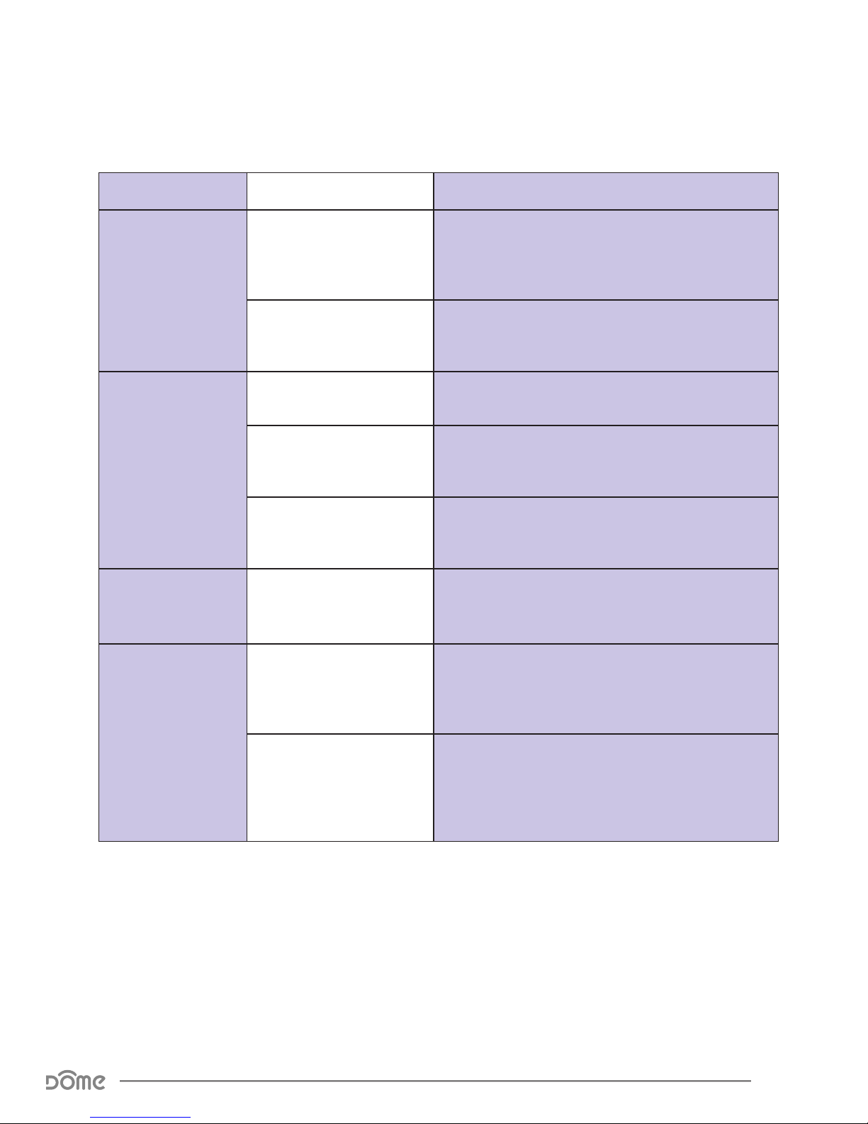
LED Behavior
Color Behavior This happens when…
Green
Red
Yellow (Green +
Red)
Blinks Twice Within 5
Seconds
Blinks 3 times quickly
Stays on for 5 seconds
Blinks 3 Times quickly
Blinks indenitely
Blinks Indenitely
…the sensor Detects the Magnet moving away or
getting close (as the Door is opened or closed)
and Z-Wave signal strength is high.
…the device is successfully included into the
system.
…the device is reset to factory settings.
… the Button is pressed 3 times quickly and the
device is excluded from the network.
…the Sensor Cover is removed and the device is
already included in a system.
...the Sensor Cover is removed and the device is
not yet included in a system.
Two Flashes (Green-Red)
Within 5 Seconds
Red & Green
Flashing in alternating
Door/Window Sensor Advanced User Manual
LED Behavior
…the sensor Detects the Magnet moving away or
getting close (as the Door is opened or closed)
and the Z-Wave signal was not received.
…the Door/Window Sensor is in inclusion mode.
It will continue blinking and remain in inclusion
colors
Table 2 - LED Blinking Behavior
mode for up to two minutes, until it is included in a
system.
Page 11
Page 12
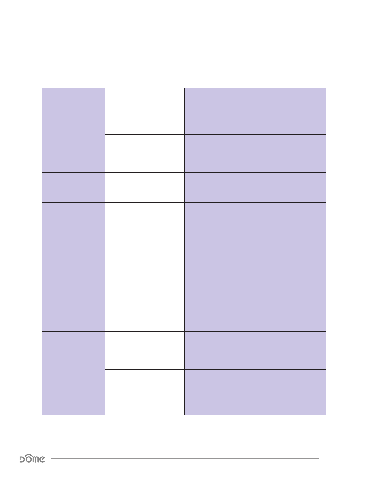
Button Behavior
Action Condition Result
Open the Cover
Open the Cover,
then Replace it
Push Button 3
Times
Door/Window Sensor Not
Yet Included in System
Door/Window Sensor
Already Included in
System
Door/Window Sensor
Already Included in System
Door/Window Sensor
Already Included in
System
Door/Window Sensor
Already Included, and
Controller is in Exclusion
Mode
LED Indicator blinks yellow (red + green) until the
Sensor Cover is replaced
Device sends a tamper notication to its controller,
awaits further instructions, and the LED Indicator
blinks red until the Sensor Cover is replaced
Device sends a wake up notication to the main
controller and awaits further instructions.
Device sends node info to Group 1
Device is excluded from the system and re-
moves the Home ID from its memory
Door/Window Sensor Not
Yet Included in System,
and Controller is in
Inclusion Mode
Door/Window Sensor
Move the Magnet
Already Included in
and Sensor In
and Out of the
Closed Position 6
Times with Cover
Removed
Door/Window Sensor Advanced User Manual
Button Behavior
Any condition (as long as
the device has power)
System
Table 3 - Button Behavior
Device enters inclusion mode and includes into
whichever network is also in inclusion mode
Device will be reset to factory settings, and a
DEVICE_RESET_LOCALLY command will be sent
to Group 1
The device’s memory will erase to factory default
settings and any associations, conguration
parameters, and other locally saved data will be
lost
Page 12
Page 13
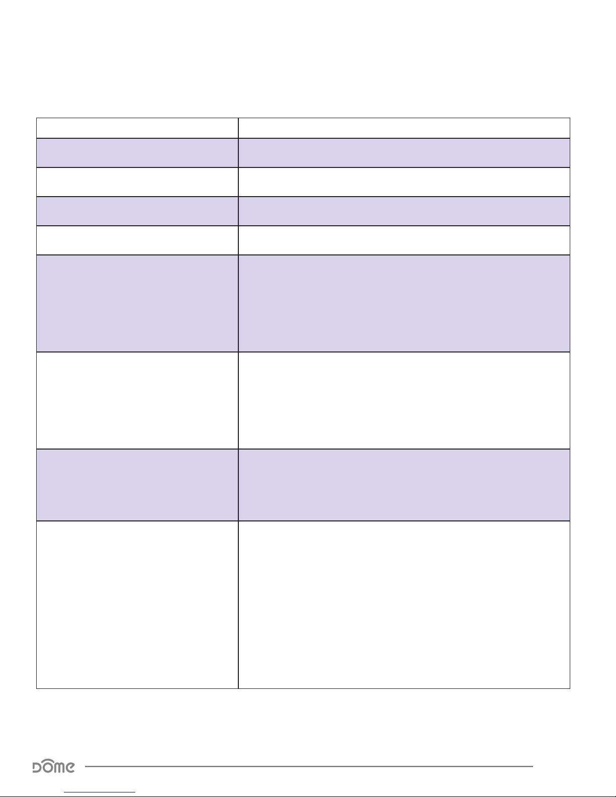
Compatible Command Classes
Command Class Notes
Device Reset Locally V1 (5A) -
Powerlevel V1 (73) -
Battery V1(80) -
Association Group Information V1 (59) -
Returned Value: 01 06 00 0C 06 0C 06
Z-Wave Plus Version: 01
Z-Wave Plus Info V2 (5E)
Role Type: 06
Node Type: 00
Installer Icon Type: 0C 06
User Icon Type: 0C 06
(Slave Sleeping Reporting)
(Z-Wave Plus Node)
(Access Control Alarm)
Returned Value: 03 04 21 01 11 1E 00
(Access Control Alarm)
Version V2 (86)
Manufacturer Specic V2 (72)
Binary Sensor (30)
Z-Wave Library Type: 03
Protocol Version: 04 21
Protocol Sub-Version: 01 11
Application Version: 1E
Application Sub-Version: 00
Manufacturer ID: 02 1F
Product Type: 00 03
Product ID: 02 01
If Conguration Parameter 3 is set to 01, the Door/Window Sensor
sends a Binary Sensor Report when opened or closed and also when
tamper events are detected. See below for the SENSOR_BINARY_REPORT
parameters sent:
Sensor Type: 0A
OPEN Value: FF
CLOSE Value: 00
Sensor Type: 08
Tamper Detected Value: FF
No Tamper Detected Value: 00
(Door/Window)
(Tamper)
(Enhanced Slave)
Returned Value: 02 1F 00 03 02 01
Door/Window Sensor Advanced User Manual
Compatible Command Classes
Table 4 - Command Classes
Page 13
Page 14

Command Class Notes
The wake-up interval is set in minutes, and is 120 minutes (two
hours) by default. The wake-up interval can be set to any value from
Group 1
Group 1 is the “Lifeline” group, which can hold ve members, typically
including the main Z-Wave controller. The Door/Window Sensor sends
this group a Notication Report or a Binary Sensor Report when it is
opened or closed (see Conguration Parameter 3.) It also sends this
group a multilevel sensor report to report the temperature (if Conguration Parameter 4 is set to 01)and a Battery Report in response to Battery
Get commands.
Group 2
Group 2 supports up to 5 members and the Door/Window Sensor sends a
Basic Set command to this group (or the Control Group) to directly trigger
devices (like a light, chime, etc.) when the tamper switch either opens or
closes. The value of the Basic Set command (e.g. brightness of the lamp) is
congured using conguration parameter 07.
Association V2 (85)
Group 3
Group 3 supports up to 5 members and the Door/Window Sensor
sends it a NOTIFICATION_REPORT or SENSOR_BINARY_REPORT
when the tamper switch either opens or closes.
Group 4
Group 4 supports up to 5 members and the Door/Window Sensor sends
a Basic Set command to this group to directly trigger devices (like a light,
chime, etc.) when the sensor detects the door/window opening or closing. The value of the Basic Set command (e.g. brightness of the lamp) is
congured using conguration parameters 08 and 09.
Wake Up V2 (84)
Table 5 - Command Classes Continued
Group 5
Group 5 supports up to 5 members and the Door/Window Sensor sends
it a NOTIFICATION_REPORT or SENSOR_BINARY_REPORT when the sensor
detects the door/window opening.
1 min up to 10,080 min (7 days) in 1-min increments.
Door/Window Sensor Advanced User Manual
Compatible Command Classes
Page 14
Page 15

Command Class Notes
default.) Conguration Parameter 05 is used to “oset” the reported value
If Conguration Parameter 3 is set to 00, the Door/Window Sensor sends
a Notication Report to the main controller whenever the door is opened
and closed and also when tamper events are detected. Two dierent
Notication Types are used to achieve this.
Returned Value: 00 00 00 FF XX XX 00 00
Notication V4 (71)
Multilevel Sensor (31)
V1 Alarm Type: 00
V1 Alarm Level: 00
Reserved: 00
Notication Status: FF
(Unsupported)
(Unsupported)
(Reserved)
(Unsolicited Reporting is Enabled)
Notication Type:
Door—06
Tamper—07
(Access Control)
(Home Security)
Event:
Door Open—16
Door Closed—17
Tamper Detected—03
No Tamper Detected—00
(Window/Door is Open)
(Window/Door is Closed)
(Tampering, Product Covering Removed)
(Event Inactive)
Sequence/Reserved/Event Parameters Length: 00
Notication Event Parameters: 00
(No Event Parameters)
The Door/Window Sensor monitors ambient temperature levels and
reports this data to the main controller using the Multilevel Sensor
command class if Conguration Parameter 04 is set to 01 (this is o by
(add or deduct a static number from the reported value) and Conguration Parameter 06 switches between Celsius and Fahrenheit.
Returned Value: 01 XX XX
Sensor Type: 01
(Temperature)
Precision/Scale/Size:
Celsius—01
Fahrenheit—09
Sensor Data: 00 ~ FF
(Precision = 000; Scale = 00; Size = 001)
(Precision = 000; Scale = 01; Size = 001)
(0 ~ 255 in Degrees Fahrenheit or Celsius)
Conguration V1 (70) See ““Conguration” Command Class Parameters” on page 16.
Door/Window Sensor Advanced User Manual
Compatible Command Classes
Table 6 - Command Classes Continued
Page 15
Page 16
“Conguration” Command Class Parameters
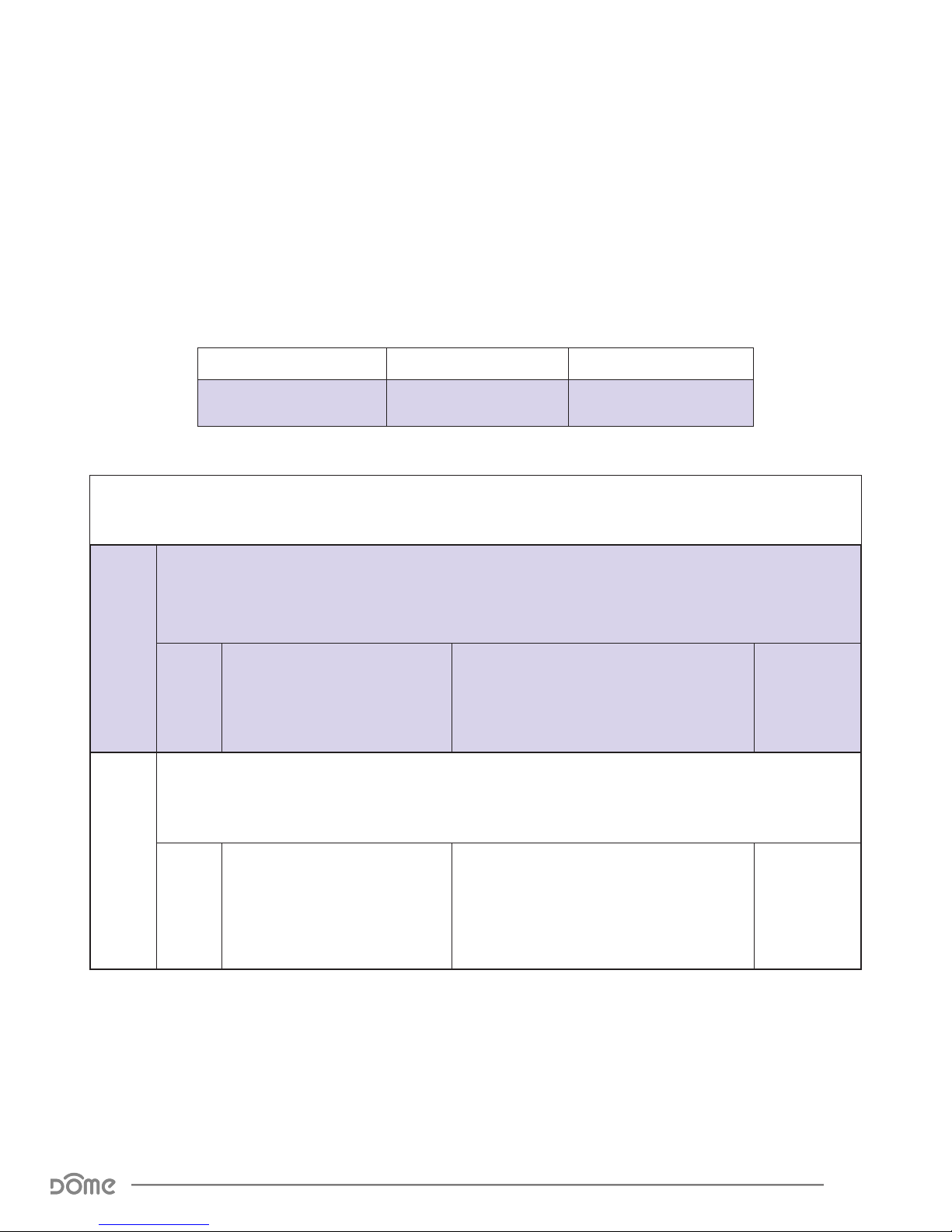
Configuration parameters are sent using a standard syntax to ensure interoperability between all manufacturers’ products. All values are represented using
the hexadecimal number system.
Typical syntax is as shown below. Note that the value sent must be the exact
size, in bytes, as accepted by the setting. The “extra” spaces should be filled
with zeros (see the “value” column below.)
Example Configuration Parameter: 02 02 00 0A
Param # Size Value
02
(Param #2)
02
(2 Bytes)
Param
# Size Name Available Values
This parameter enables or disables the LED Indicator ashing to indicate opening and closing
events. The Door/Window Sensor will always ash the LED Indicator for inclusion, exclusion,
tamper, and other system events.
01
00
01
This parameter switches the Notication or Binary Sensor report sent when the door opens or closes. If this
parameter is set to 01, the Door/Window Sensor will report “closed” instead of “open”when the Magnet and
Enable/Disable LED Indicator
Sensor are pulled apart.
(Open/Close LED Indicator Disabled)
01
(Open/Close LED Indicator Enabled)
00 0A
(10)
Default
Value
01
(Open/Close
LED Indicator
Enabled)
02
01
Door/Window Sensor Advanced User Manual
“Conguration” Command Class Parameters
Congure Open/Close Reports
Table 7 - Door/Window Sensor Conguration Parameters
Sent
00
(Reports Closed when Magnet is close)
01
(Reports Open when Magnet is close)
00
(Reports
Closed when
Magnet is
close)
Page 16
Page 17
Param
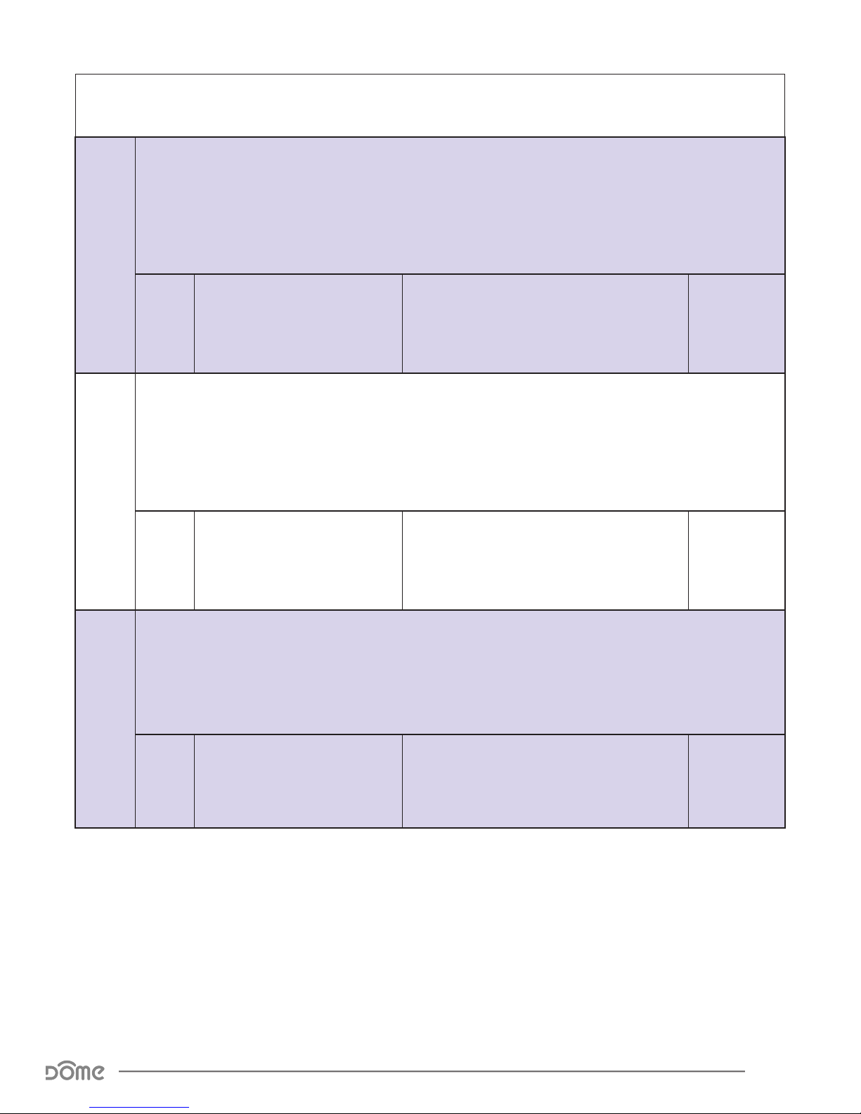
# Size Name Available Values
By default, the Door/Window Sensor uses the Notication command class to communicate open/close
and tamper events. If this Parameter is set to 1, the device will instead use the Binary Sensor command
class.
To apply this setting, the battery needs be removed and replaced! This is because the supported
command classes will change according to this setting, so the device must restart to advertise its new
03
04
01
Switch Between Notication and
Binary Sensor Command Classes
The Door/Window Sensor can also monitor and report ambient temperature conditions. However, tem-
perature sensing functionality is disabled by default to save battery life, and this conguration parame-
ter is used to enable or disable this feature.
To apply this setting, the battery needs be removed and replaced! This is because the supported
command classes will change according to this setting, so the device must restart to advertise its new
command classes.
00
(Notication Command Class is Used)
01
(Binary Sensor Command Class is Used)
command classes.
Default
Value
00
(Notication
Command
Class is Used)
05
00
01
Enable/Disable Temperature
Sensor
(Temperature Sensor Disabled)
01
(Temperature Sensor Enabled)
This Conguration Parameter can oset the temperature value reported by ± 125 degrees
to compensate for temperature variances in a room - for example, the temperature near the
ceiling in a room is signicantly higher than the average temperature of the same room. This
Parameter accepts a signed 8-bit value with an absolute value of up to 125, and its units are
Dependant on Conguration Parameter 07
00~7D
01
Temperature Oset
83~FF
(0o~125o)
(-125o~-1o)
Table 8 - Door/Window Sensor Conguration Parameters
00
(Temperature
Sensor
Disabled)
00
(0o Oset)
Door/Window Sensor Advanced User Manual
“Conguration” Command Class Parameters
Page 17
Page 18

Param
# Size Name Available Values
The Door/Window Sensor can report temperature values in either Celsius or Fahrenheit, and
this parameter allows the user to decide which unit is used.
06
00
(Temperature is Reported in Fahrenheit)
01
(Temperature is Reported in Celsius)
00
(0/Turn O Device)
01 ~ 63
FF
(255/Turn On Device)
07
01
Temperature Units
This parameter sets the value sent by the Basic Set command to Association Group 2. The
Door/Window Sensor sends a Basic Set command to Association Group 2 both when the tamper
switch opens and closes (for more information, see “Group 2” on page 14.)
01
Basic Set Value (Group 2)
(0-99)
Default
Value
00
(Temperature
is Reported in
Fahrenheit)
FF
(255/Turn On
Device)
08
09
This parameter sets the value sent by the Basic Set command to Association Group 4. The
Door/Window Sensor sends a Basic Set command to Association Group 4 when the door or window
opens (for more information, see “Group 4” on page 14.)
00
01
Basic Set Level (Group 4 Opening)
(0/Turn O Device)
01 ~ 63
FF
(255/Turn On Device)
(0-99)
FF
(255/Turn On
Device)
This parameter sets the value sent by the Basic Set command to Association Group 4. The
Door/Window Sensor sends a Basic Set command to Association Group 4 when the door or window
closes (for more information, see “Group 4” on page 14.)
00
01
Basic Set Level (Group 4 Closing)
(0/Turn O Device)
01 ~ 63
FF
(255/Turn On Device)
(0-99)
00
(0/Turn O
Device)
Table 9 - Door/Window Sensor Conguration Parameters
Door/Window Sensor Advanced User Manual
“Conguration” Command Class Parameters
Page 18
Page 19

Troubleshooting
:Q Help! My Door/Window Sensor paired successfully, but my con-
troller can’t see it anymore after I installed it!
:A First, make sure your battery didn’t come loose during set-up. Otherwise,
the Z-Wave signal is probably weak in that area of your home. Remember
that the 120' - 150' range doesn’t take into account walls, furniture, and
other obstacles. To boost your Z-Wave network coverage, add a few nonbattery powered Z-Wave devices between the controller and the furthest
device, like the Dome On/Off Plug or Water Main Shut-Off. You can even
purchase dedicated Z-Wave extenders from 3rd party manufacturers.
:Q There’s so many words in this manual I don’t understand. How
can I learn more about Z-Wave?
:A Remember you don’t have to understand everything in this manual to
start automating your home. Our Quick-Start Guides have all you need
to start using any device. For more thorough information about Z-Wave
home automation, visit www.domeha.com/support.
:Q My sensor keeps telling me it’s open when my door is closed!
:A Your magnet and sensor are probably too far apart. Try remounting one
of them closer to the other, and it should start working consistently.
:Q I’ve tried multiple times, but I can’t include the Door/Window Sensor
in my system.
:A Check your battery and make sure your device is getting power. Then,
follow the instructions under “Factory Reset & Misc. Functions” on page
8 and try going through the inclusion process again. If you are still
having issues, please visit www.domeha.com/support
:Q All of a sudden, my Door/Window Sensor is offline.
:A Check your battery and make sure your device is getting power. If
powered, make sure you still have Z-Wave network coverage. If you are
still having issues, visit www.domeha.com/support.
Door/Window Sensor Advanced User Manual
Troubleshooting
Page 19
Page 20

Warranty & Support
If you have questions, our trained Customer Service Department is happy to assist you 24 hours a day, 7 days a week. Contact Dome Customer Service as follows: • In North America dial: 1-855-249-1754 • Email
Dome at [email protected]
DO NOT RETURN THIS PRODUCT TO THE STORE OR WEBSITE FROM
WHICH IT WAS PURCHASED
If you believe the product is defective, has a missing or broken part or
are having difficulty with it please contact Dome as listed above for a
quick and efficient solution to the problem.
Legal Notices: This device complies with part 15 of the FCC rules. Operation is subject to the following two conditions (1) This device may
not cause harmful interference, and (2) this device must accept any
interference received, including interference that may cause undesired
operation.
Note: This equipment has been tested and found to comply with the
limits for a Class B digital device, pursuant to part 15 of the FCC Rules.
These limits are designed to provide reasonable protection against
harmful interference in a residential installation. This equipment generates, uses and can radiate radio frequency energy and, if not installed
and used in accordance with the instructions, may cause harmful interference to radio communications.
However, there is no guarantee that interference will not occur in a particular installation. If this equipment does cause harmful interference
to radio or television reception, which can be determined by turning the
equipment off and on, the user is encouraged to try to correct the
Interference by one or more of the following measures: Reorient or
relocate the receiving antenna; increase the separation between the
equipment and the receiver; connect the equipment into an outlet on a
circuit different from that to which the receiver is connected. Consult
the dealer or an experienced radio/TV technician for help.
This device complies with Industry Canada license-exempt RSS standard(s). Operation is subject to the following two conditions: (1) this
device may not cause interference, and (2) this device must accept any
interference, including interference that may cause undesired operation of the device.
Elexa Consumer Products, Inc. (”ECP”) warrants to the original retail
purchaser (”Purchaser”) that the DOME Window/Door sensor (the
“Product”) will be free of defects in materials or workmanship under
use for one (1) year from the date of purchase (the “Warranty period”).
For the Purchaser only, if the Product fails to perform as specified
during the Warranty Period due to defective parts or faulty workmanship, ECP will repair or replace the defective or damaged parts of the
Product. Normal wear and tear is not covered nor is abnormal use,
misuse, mishandling, faulty installation, improper shipping, damage
caused by disasters such as fire, flood or earthquake, neglect, accident
or tampering. This warranty covers only normal use in the United States
or Canada.
To obtain warranty service during the Warranty Period, call Dome Customer Service (1-855-249-1754) or email: [email protected] for
instructions on sending damaged parts and documentation for a Return Material Authorization (RMA). Products returned to ECP for repair
or replacement without authorization will be returned at the sender’s
expense. All warranty claims must be accompanied by a legible copy
of the original receipt showing date and details of purchase. The RMA
number must be clearly written on the side of the shipping container
in which you return the Product or defective parts. Unless otherwise
instructed by ECP, the Product must be sent freight pre-paid to the following address:
Elexa Consumer Products, c/o Promac,
1153 Timber Dr., Elgin, IL 60123
ECP will repair or replace the defective parts and return them at ECP’s
cost by a shipping method selected by ECP. When contacting ECP to
obtain an RMA, Purchaser may request expedited return shipping at
Purchaser’s expense.
THIS WARRANTY IS NOT TRANSFERABLE, AND, TO THE MAXIMUM
EXTENT PERMITTED BY APPLICABLE LAW IS IN LIEU OF ALL OTHER
WARRANTIES, REPRESENTATIONS AND CONDITIONS, EXPRESSED OR
IMPLIED, STATUTORY OR OTHERWISE, INCLUDING BUT NOT LIMITED
TO THE IMPLIED WARRANTIES OF MERCHANTABILITY AND FITNESS
FOR A PARTICULAR PURPOSE. NO OTHER PERSON OR REPRESENTATIVE IS AUTHORIZED TO MAKE ANY OTHER WARRANTY ON BEHALF
OF ECP OR ASSUME FOR ECP ANY OTHER LIABILITY IN CONNECTION
WITH THE SALE OF THIS PRODUCT. IN NO EVENT WILL ECP BE LIABLE
FOR ANY DAMAGES, INCLUDING BUT NOT LIMITED TO INCIDENTAL,
SPECIAL OR CONSEQUENTIAL DAMAGES ARISING OUT OF THE USE
OR INABILITY TO USE THE PRODUCT, INCLUDING DAMAGES DUE TO
ECP’S NEGLIGENCE.
THIS WARRANTY GIVES YOU SPECIFIC LEGAL RIGHTS, AND YOU MAY
ALSO HAVE OTHER RIGHTS WHICH VARY FROM STATE TO STATE AND
COUNTRY TO COUNTRY.
This marking on the product, accessories or literature indicates that the
product and its electronic accessories should not be disposed of with
other household waste.
To prevent possible harm to the environment or human health from
uncontrolled waste disposal, please separate these items from other
types of waste and recycle them responsibly to promote the sustainable reuse of material resources.
Household users should contact either the retailer where they purchased this product, or their government office, for details of where
and how they can take these items for
Environmentally safe recycling.
Business users should contact their supplier and check the terms and
conditions of the purchase contract. This product and its electronic accessories should not be mixed with
other wastes for disposal.
This marking on the battery, manual or packaging indicates that the
batteries in this product should not be disposed of with other household waste. Where marked, the chemical symbols Hg, Cd or Pb indicate
that the battery contains mercury, cadmium or lead above the reference
levels in EC Directive 2006/66. If batteries are not properly disposed of,
these substances can cause harm to human health or the environment.
Door sensor is a wireless intelligent alarm system, which is used to
detect whether the doors, windows, drawers, etc. are illegally opened or
moved. It consists of two parts-wireless transmitter and magnet, when
the magnet close or leave a certain distance it trigger pulse circuit to
pulse. The main control IC is awoken and transmit a wireless signal, the
transmission frequency is 908MHz. It also supports tamper, OTA, and
temperature sensor function.
Door/Window Sensor Advanced User Manual
Warranty & Support
Page 20
 Loading...