

Page 1
domat UC010 08/2018 Subject to technical changes. 1
UC010
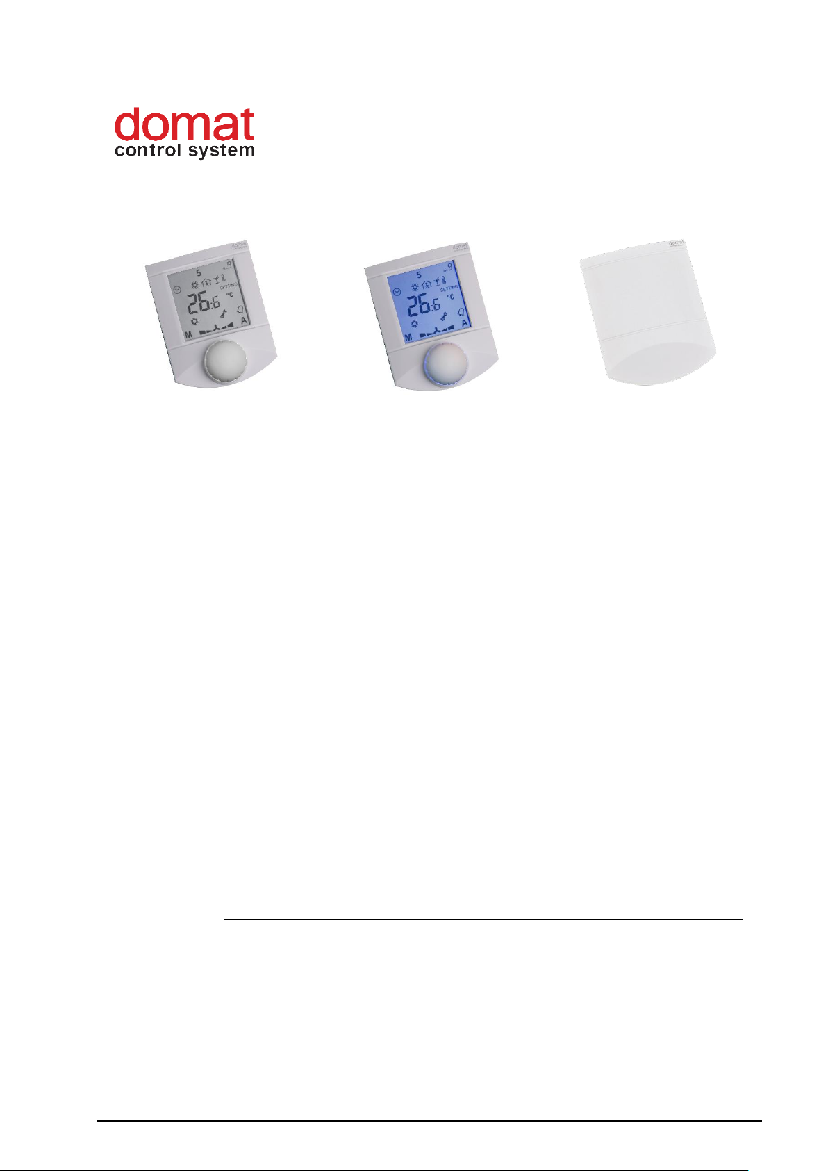
Room unit for fancoil controller FCR010
Summary
The UC010 room unit is a communicative human-machine interface for fancoil
controller FCR010.
According to production type, each version of the unit may contain display, backlight
and knob.
UC010 – basic version with display and knob
UC010BL – version with display, knob and backlight
UC010DK – version without knob and display
Application
▪ Fan coil systems – measurement and control of room temperature
Function
The unit reads room temperature, temperature correction / setpoint by a knob, and
required operation mode which is set by a short push or in the menu. Data is
transmitted to the fancoil controller. The fan coil controller may send to the unit other
data (heating / cooling mode, fan stage, day / night / standby mode etc.) which are
displayed on the LCD display.
Connect the room unit to FCR010 over a 4 core cable, the most suitable types are JY(St)Y
or LAM 2x2x0.8. Use the same type which powers the FCR010 controller as if the room
unit power is taken from the FCR010 terminals, the cores in a terminal should be of the
same cross-section.
If there is communication failure between UC010 and FCR010, there is a wrench and
alarm bell icon at the UC010 display. Check signal polarity (terminals 3, 4), bus
termination, and correct wiring at the FCR010 side (see FCR010 data sheet).
Technical data
Power supply
24 V AC +/- 20%
Consumption
1 W
Communication
RS485, Modbus RTU,
selectable speed 1200 ... 115200 bps
SW
ModComTool
Page 2
2 08/2018 Subject to technical changes. domat UC010
Temperature measuring range
-20 ÷ 70 °C (accuracy ±1 ˚C)
Humidity measuring range
10 ÷ 90 rH (accuracy ±3 % rH)
Setpoint
as configured, +/- 10 to +/- 1 K
Display
LCD 60 x 60 mm
Terminals
screw terminals for wires 0,14 – 1,5 mm2
Cover
ABS, RAL9010, other colours
Protection
IP20
Weight
0,13 kg
Dimensions
90x115x30 mm
Ambient temperature
External conditions: -5 – 45 °C; 5 – 95 % relative
humidity; non-condensing gases and chemically
non-aggressive conditions (according to EN
60721-3-3 climatic class 3K5
Storage: -5 – 45 °C; 5 – 95 % relative humidity;
non-condensing gases and chemically nonaggressive conditions (according to EN 60721-3-1
climatic class 1K3)
Standards conformity
EMC EN 61000-6-2 ed.3:2005, EN 61000-6-4
ed.2:2006 + A1:2010 (industrial environment)
Electrical safety EN 60950-1 ed.2:2006 +
A11:2009 + A12:2011 + A1:2010 + A2:2014 +
Opr.1:2012 + Z1:2016
Hazardous substances reduction EN 50581:2012
Version UC010DK without knob and display is available.
Version with display and without knob is also available, need to be specified in order.
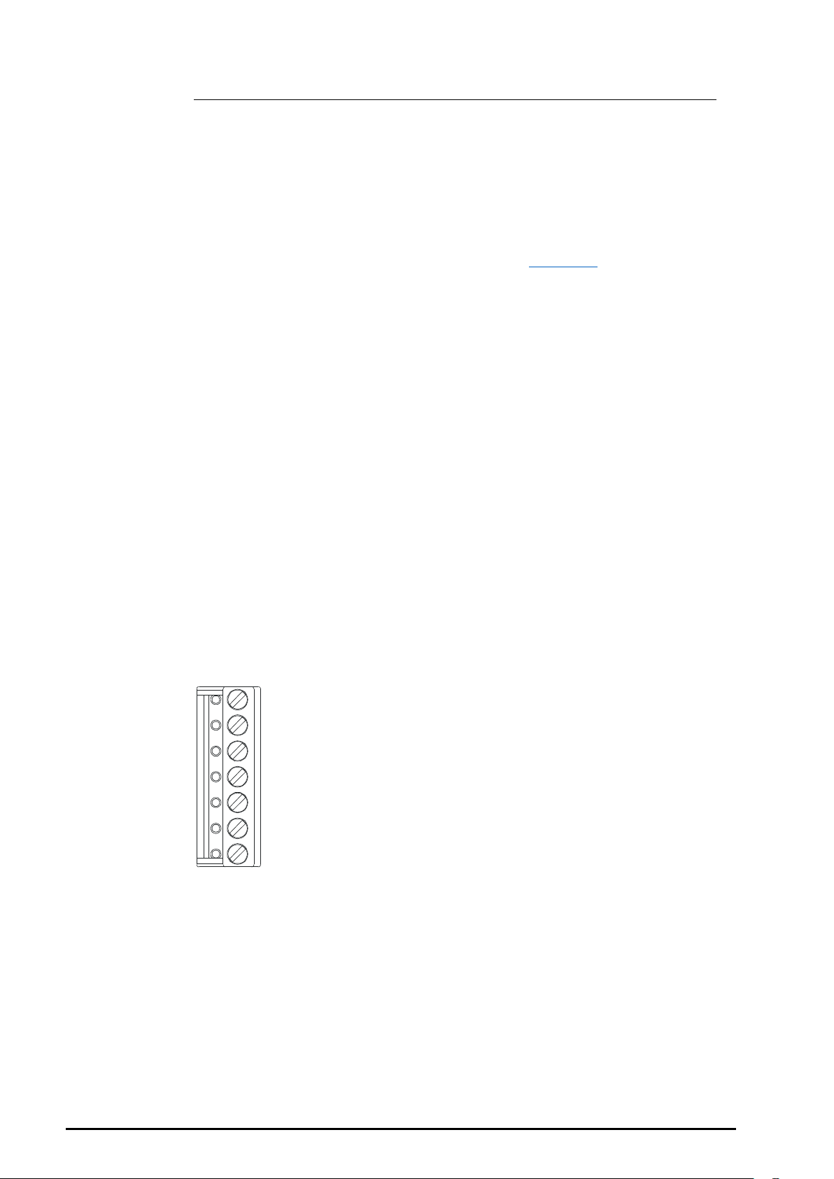
Terminals
1
2
3
4
5
6
7
1: NC not connected
2: NC not connected
3: K- communication, RS485 –
4: K+ communication, RS485 +
5: GND technical earth (TE)
6: G0 power – common point
7: G power
Page 3

domat UC010 08/2018 Subject to technical changes. 3
DIP switches
Back of the PCB
BUS END: if ON, the bus is terminated (if last
device on the line)
USR: not used, reserved for future
applications
INIT: sets the controller into default state and
sets bus address to 1, baud rate to 9600.
To init, proceed as follows:
- connect the device over RS485 to a
PC with ModComTool config tool
- set INIT to ON
- apply power (use only the connector
without bottom)
- find the controller in the tool (Scan)
- set INIT to OFF
- in the ModComTool, open the
controller window
- click the Init button in the tool
- remove and apply power.
Installation
Units are intended for operating in a normal and chemically non-aggressive
environment. They do not need any servicing or maintenance. Install them in a vertical
position at places where they can be operated easily and measure correct values of
temperature, i.e. in the height of about 150 cm, with no direct sunlight or other heat /
cool source (AHU outlets, refridgerator, electrical appliances). The device consists of
two parts: bottom with screw terminal block and cover containing PCB, display, and the
knob. The bottom part is fixed by 2 or 4 screws to any flat surface or a flush-mounting
box Ø 50 mm. At the back of the bottom there is an aperture for cabling. The bottom
should be installed and cabling connected first, and the upper part inserted after the
construction works have been finished to prevent damage to the unit.
Seal the conduits to avoid influencing the sensor by draught. Use insulating pad when
installing the sensor on cold walls. Avoid sensor exposition to sunlight or other heat
sources.
Cover opening
When removing the display part, proceed as follows:
- press gently the side parts of the unit and pull the right of the display part by
several milimeters
- pull the left of the display part
Page 4

4 08/2018 Subject to technical changes. domat UC010
- pull the display part and remove it from the bottom.
Do not bend the display part too much, the connector pins could be damaged. The locks
are only at the sides of the display part, not at the top nor bottom.
Operation
The following settings are defaults. The engineer may set another way of fancoil
control, disable some functions etc., so the text below is a description of the default
functionality of the controller rather than the user operation manual.
Temperature correction:
Turn the knob clockwise to increase setpoint, turn it counterclockwise to decrease
setpoint. The maximum correction range can be modified over the bus e.g. with the
ModComTool configuration tool.
Fancoil stage setting:
Push the knob shortly (<1 s). Every push changes the fancoil stage cyclically: Stage 1 –
Stage 2 – Stage 3 – Off – Auto. When changing between the Comfort and Standby
modes, the controller falls back into automatic fancoil stage control according to the
control deviation.
Operation mode change:
The operation mode in the Hotel mode (used for fancoils in hotels and offices) is
changed over bus communication or by activating digital inputs. The DI1 switches
between the Comfort and Standby modes (e.g. card reader), while DI2 brings the
controller into the Off mode (e.g. window contact). The time scheduler is used with
Residential mode only.
Time schedule settings:
Switch to the time schedule settings mode with a long push (>1 s). The controller
switches to settings mode (clock icon).
Turn the knob to select the weekday (1 to 7). Then short push to confirm the selection.
Turn the knob to select the event (large number 1 to 6). Each event displays the mode
activated by this event.
Short push to confirm the event selection. Turn the knob to select the operation mode
(Day, Night, Off, Event inactive) invoked by this event. If the event is not active, the
operation mode is not changed at the set time.
Page 5
domat UC010 08/2018 Subject to technical changes. 5
Short push to confirm the operation mode setting. The event time displays. Turn the
knob to set the time of the event and confirm by a short push. Then turn the knob to
select another event or long push and turn the knob to select another weekday.
After all desired events have been edited, long push to leave the time schedule settings.
The controller goes to the basic display mode also after 30 secs of user inactivity.
Change of setpoints and controller time:
Switch to the settings mode with a superlong push (>2.5 s). The controller switches to
settings mode (flashing thermometer icon).
Turning the knob selects between following settings:
- Controller time and day of week (Clock icon, Day of week)
- Setpoint temp. Heating Day mode (Temperature, Heating, Day are flashing)
- Setpoint temp. Heating Night mode (Temperature, Heating, Night are flashing)
- Setpoint temp. Heating Off mode (Temperature, Heating, Empty house are
flashing)
- Setpoint temp. Cooling Day mode (Temperature, Cooling, Day are flashing)
- Setpoint temp. Cooling Night mode (Temperature, Cooling, Night are flashing)
- Setpoint temp. Cooling Off mode (Temperature, Cooling, Empty house are
flashing)
Select the requested value by a short push. Turn knob to change value. Confirm by a
short push again.
If there is no user activity for 30 s, the controller goes to the basic display mode.
Default values:
The default values as well as all other settings (PI parameters, address, baudrate...) can
be set by the configuration program, ModComTool.
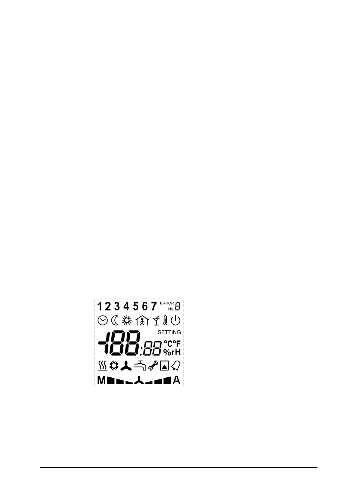
Display
A large (60 x 60 mm) display clearly shows
actual room temperature and controller status
with 7-segment digits and standard Day, Night,
Off, and Time scheduler symbols. Active output
is indicated by a heating symbol. In the upper
part, there are week days used for time
scheduler setup. Other symbols are not used.
LCD symbol set
Page 6
6 08/2018 Subject to technical changes. domat UC010
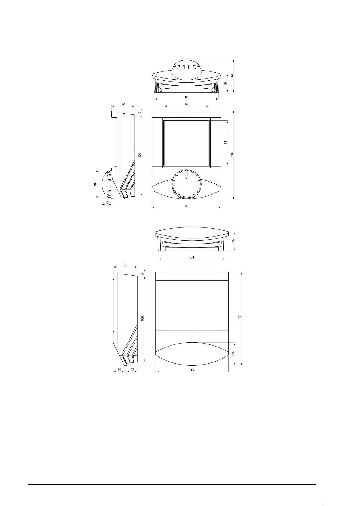
Dimensions
UC010
UC010DK
All dimensions in mm.
Safety note
The device is designed for monitoring and control of heating, ventilation, and air
conditioning systems. It must not be used for protection of persons against health risks
or death, as a safety element, or in applications where its failure could lead to physical
or property damage or environmental damage. All risks related to device operation
must be considered together with design, installation, and operation of the entire
control system which the device is part of.
Page 7

domat UC010 08/2018 Subject to technical changes. 7
Changes in
versions
04/2015 – Added UC010/DK version.
08/2016 – Changed the format and reference to the configuration software.
03/2017 – Added picture and description of the installation and link on the datasheet
with other colours.
07/2017 – Change of technical data, standards and images. BL version added.
08/2017 – Controller description change (FC to FCR version).
08/2018 – Minor changes.
 Loading...