

Page 1

EDV
-
Nr. 29806
1
/ 0 / gb / 08.09 Rev. D
Assembly Instructions
Key system
Sigma Plus
(Profile 145)
Page 2

Notes
Page 3

Sigma Plus Contents
1
Contents
PRODUCT DESCRIPTION......................................................................................... 3
YOUR SAFETY .......................................................................................................... 4
Important Notes........................................................................................................ 4
SCOPE OF DELIVERY .............................................................................................. 5
PREPARATION.......................................................................................................... 6
Tools ........................................................................................................................ 6
Service box .............................................................................................................. 7
ASSEMBLY................................................................................................................ 8
Preparation of assembly superstructure................................................................... 9
Filling of cylinder body............................................................................................ 13
Filling of cylinder core............................................................................................. 21
Insertion of the cylinder core into cylinder body ..................................................... 24
Type 333 ................................................................................................................ 25
Type 333H.............................................................................................................. 27
Type 333T .............................................................................................................. 29
Type 333K.............................................................................................................. 31
Type 333KL............................................................................................................ 34
Type 382 ................................................................................................................ 37
Type 555 ................................................................................................................ 39
Type 777 ................................................................................................................ 41
MAINTENANCE ....................................................................................................... 43
STORAGE/MAINTENANCE..................................................................................... 43
DISPOSAL ............................................................................................................... 43
TECHNICAL DATA SIGMA PLUS ........................................................................... 44
Page 4

Contents
2
WARRANTY............................................................................................................. 46
WORKSHEET .......................................................................................................... 47
Page 5

Sigma Plus
Product Description
3
Product Description
The Sigma Plus system offers a high degree of flexibility, as many different locking
combinations can be obtained with the 6 sprung locking element pairs.
You can use one key to open everything – from front door to briefcase, from garage
door to window handles. You can also subsequently obtain additional cylinders for
your new Sigma Plus system, which you can open with your Sigma Plus key.
If required, we can also offer the Sigma Plus system in a modular design, to provide
an additional increase in the break-off values and length flexibility.
DOM Sigma Plus is perfectly suited for the use in (general) master key systems or
central lock (master key) systems.
Page 6
Your Safety/Important Notes
4
Your Safety
Always comply with the instructions and security statements!
In this assembly instructions, several sections are marked by graphical symbols.
Please memorise the graphical symbols and their meanings:
Caution! This symbol marks a danger note and/or refers to an action that
may cause damage to the mechanical cylinder or other objects.
Note! This symbol refers to useful information on assembly or operation.
Important Notes
Caution! Keep the mechanical cylinder and its components away from
small children. They might swallow small parts.
Caution! Material damage caused through incorrect storage. If you store
mechanical cylinders for a longer period of time before assembly, store
all components dry and dust-free in the original packaging.
Caution! Damage caused through inexpert assembly. Please read these
instructions completely and carefully before assembly. Follow the instructions step by step. The manufacturer accepts no liability for damage resulting from an inexpert assembly.
Caution! Defects caused by untrained personnel! Only extensively
trained personnel are allowed to assemble DOM cylinders. The manufacturer disclaims liability for any defects caused by untrained personnel.
Page 7

Sigma Plus
Scope of delivery
5
Scope of delivery
For each Sigma Plus contract you will receive the following documents:
1. Service card / Identification card
2. Client worksheet
3. Encoded worksheet
4. Table of assembly superstructure of the cylinder
5. Supplementary sheet for high-level keys
To fabricate spare cylinder and spare keys please use the coded worksheet, tables
of assembly superstructure of the cylinder and supplementary sheet for high-level
keys.
The principal of the locking system will receive service card and client’s worksheet.
Note! The principal of the locking system shall assure safe storage of the
service card at a place where only authorized persons have access to.
Page 8
Preparation/ Tools
6
Preparation
To ensure professional assembly you will need the assembly superstructure; the
proper core and body pins and the proper tools.
Caution! Damage caused through inexpert assembly. Please read these
instructions completely and carefully before assembly. Follow the instructions step by step. The manufacturer accepts no liability for damage resulting from an inexpert assembly.
Caution! Defects caused by untrained personnel! Only extensively
trained personnel are allowed to assemble DOM cylinders. The manufacturer disclaims liability for any defects caused by untrained personnel.
Tools
Caution! Defects caused by applying improper tools!
The tool DOM Sicherheitstechnik provides for cylinder assembly is tuned
to all requirements of professional assembly. The manufacturer disclaims
liability for any damages or defective assembly caused by the application
of other tools.
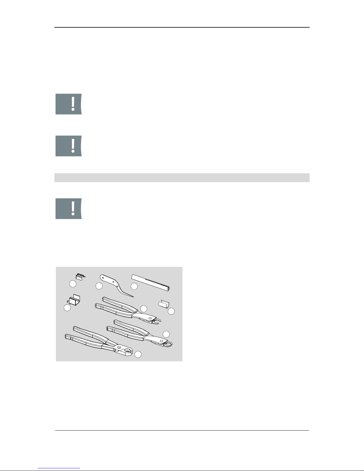
You need the following tools:
1
2
3
4
5
7
8
6
Fig. 1: Tools
1: assembly clam (400269)
2: loading knife (261674)
3: follower (266009)
4: assembly clam for type 382
(405634)
5: pliers for cam type KL (265776)
6: Assembly bushing (266674)
7: pliers for extension piece (261669)
8: pliers for cam (263629)
Page 9
Sigma Plus Preparation/ Service box
7
Service box
DOM Sicherheitstechnik has compiled an service box for system Sigma Plus that
contains all necessary sorts of pins (body pins, core pins) as well as masterkey wafers. You may order this service box directly via DOM Sicherheitstechnik. Thus you
are always well equipped with all tools and necessary pins.
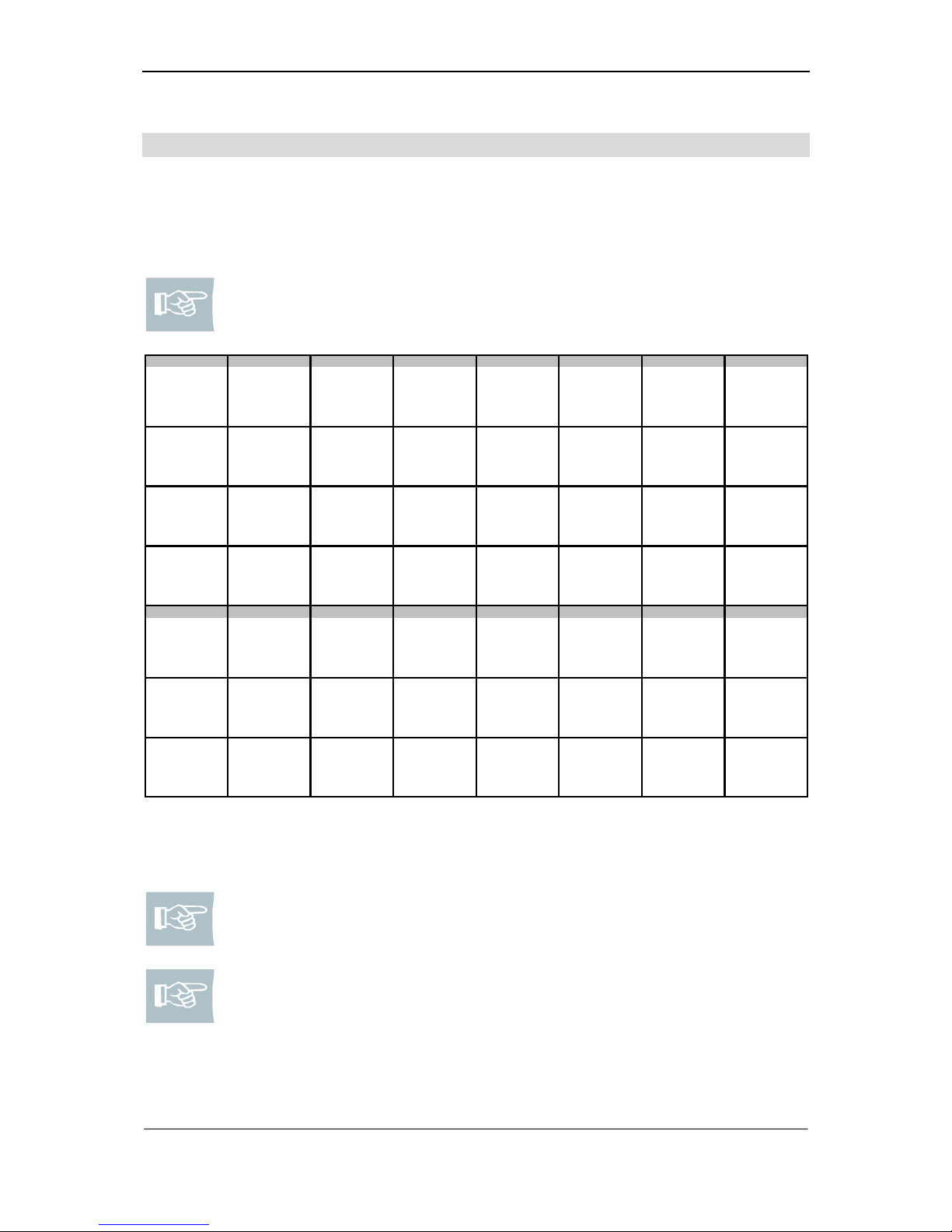
Note! This service box also exists for other systems, e.g. for ix 6 KG,
Diamant, etc..
Core pins
NNN
N
No. 0
No. 1
No. 2
No. 3
4,85 mm
5,25 mm
5,65 mm
6,05 mm
509254 112
509255 112
509256 112
509257 112
ABABAB
AB
No. 4
No. 5
No. 6
No. 7
6,45 mm
6,85 mm
7,25 mm
7,65 mm
509259 112
509260 112
509261 112
509262 112
Cam
End piece
Cam
Cam
Coupling
Coupling
half
half
standard
double entry
standard
double entry
new design
218426 008
204217
218228 008
235855 008
502154
235860
Body pins
NNFB
FB
No. 0, 1, 2, 3
No. 4, 5, 6, 7
No. 0, 1, 2, 3
No. 4, 5, 6, 7
5,5 mm
4,5 mm
5,5 mm
4,5 mm
509264 112
509265 112
509268 112
509269 112
HHH
H
No. 0, 1
No. 2, 3
No. 4, 5
No. 6, 7
5,6 mm
4,6 mm
3,6 mm
3,1 mm
509271
509272
509273
509274
Masterkey
Masterkey
Masterkey
Profile pin
Spring
Spring
Security ring
wafers
wafers
wafers
RD 2,7 x 14
V2A
0,8 mm
1,6 mm
2,4 mm
V2A
382, 393
1,0 mm
509250
509251
509252
509276
333, 555, 777
243515
202335F
242172
The box contains single compartments where you can sort in pins. The following figure shows how the wrapped pins are sorted in the service box ex works.
Note! A list of contents is part of the service box. You may make use of
the sequence of pins according to the list of contents to avoid confusion.
Note! The assembly tools may be delivered together with the service box
on your explicit order.
Page 10

Assembly
8
Assembly
Please follow the stated order and pay attention to the notes and figures.
Caution! For assembly please use only the special tool that is described
in the assembly steps. Manufacturer disclaims liability for any defects
caused by application of inappropriate tools.
Note! Please use a soft pad for assembly, such as a foam rubber. Thus
you ensure that no pins drop out of the cylinder core when placing the
core into the body.
Note! All material numbers for common spare parts are specified together with the respective step of assembly.
At first all common steps of assembly that apply for all types of cylinders will be described in the assembly instructions. So at first basic handling of the assembly superstructure, body filling, core filling and core fitting into body are specified. Subsequently each step of assembly will be described. These apply for the respective type
of cylinder only.
Page 11
Sigma Plus Assembly /Assembly without/with masterkey wavers
9
Preparation of assembly superstructure
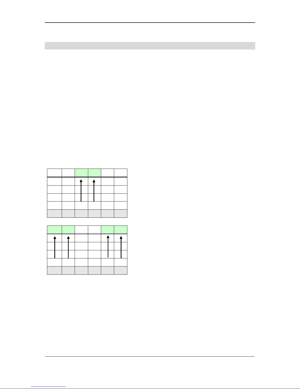
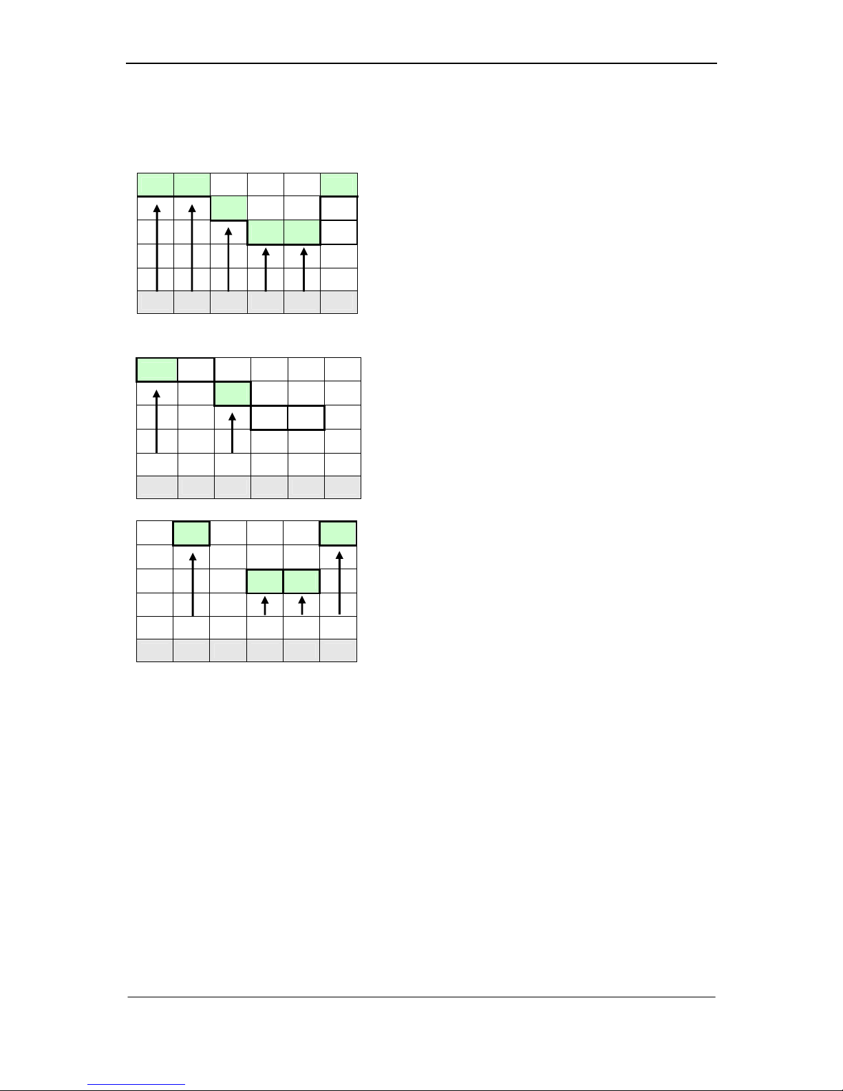
For each Sigma Plus contract you receive a sheet with tables of assembly superstructures of the cylinders. If positions of core and body pins are not stated in the table ex works please enter the pins in the table.
The following shall apply:
The FB body pins may only be assembled at the first five positions, maximally 2
at each side of the cylinder.
FB body pins are assemble to the positions with the lowest values. In case of su-
perstructures (master key system), the lowest value including the superstructure is
considered.
Only N pins are available as core pins for the lengths of 0, 1, 2, 3, and for the
lengths 4, 5, 6, 7 only AB pins are available. There is no restriction of the positions
for core pins. The core pins are applied at positions P1 – P6 depending on their
lengths.
Assembly without masterkey wafers
Body pins
4 5 1 2 3 5
FB FB
P1 P2 P3 P4 P5 P6
4 5 1 2 3 5
N N FB FB N N
P1 P2
P3 P4
P5 P6
1.) At first the two FB-body pins are inserted at
the positions P1 – P5 with the lowest val-
ues.
(here: position P3=value 1 and P4=value 2)
2.) N-pins are inserted at the remaining posi-
tions.
Page 12
Assembly /Preparation of assembly superstructures
10
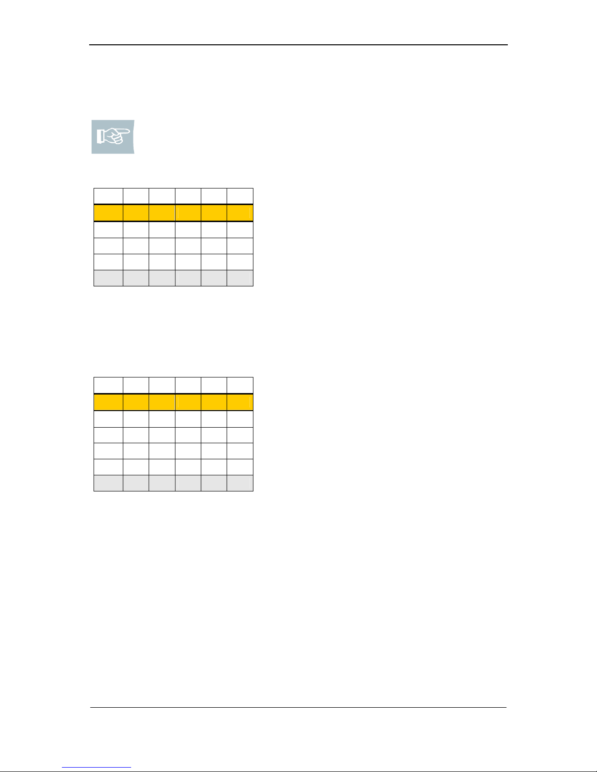
Assembly with masterkey wafers
Body pins
4 5 1 2 3 5
3 4 5
6 7
P1 P2 P3 P4 P5 P6
4 5 1 2 3 5
3 4 5
6 7
FB N FB N N N
P1 P2 P3 P4 P5
P6
4 5 1 2 3 5
3 4 5
6 7
FB N FB N N N
P1
P2
P3
P4 P5 P6
For assembly superstructures with masterkey
wafers the highest plate structure determines the
body pin as stated in the lower cells of the re-
spective columns.
1.) At first the two FB-body pins are inserted at
the positions P1 – P5 with the lowest val-
ues in the lowest cells.
(here: position P1=value 4 and P3=value 3)
2.) N-pins are inserted at the remaining posi-
tions P2, P4, P5 and P6.
Page 13
Sigma Plus Assembly /Assembly without/with masterkey wavers
11
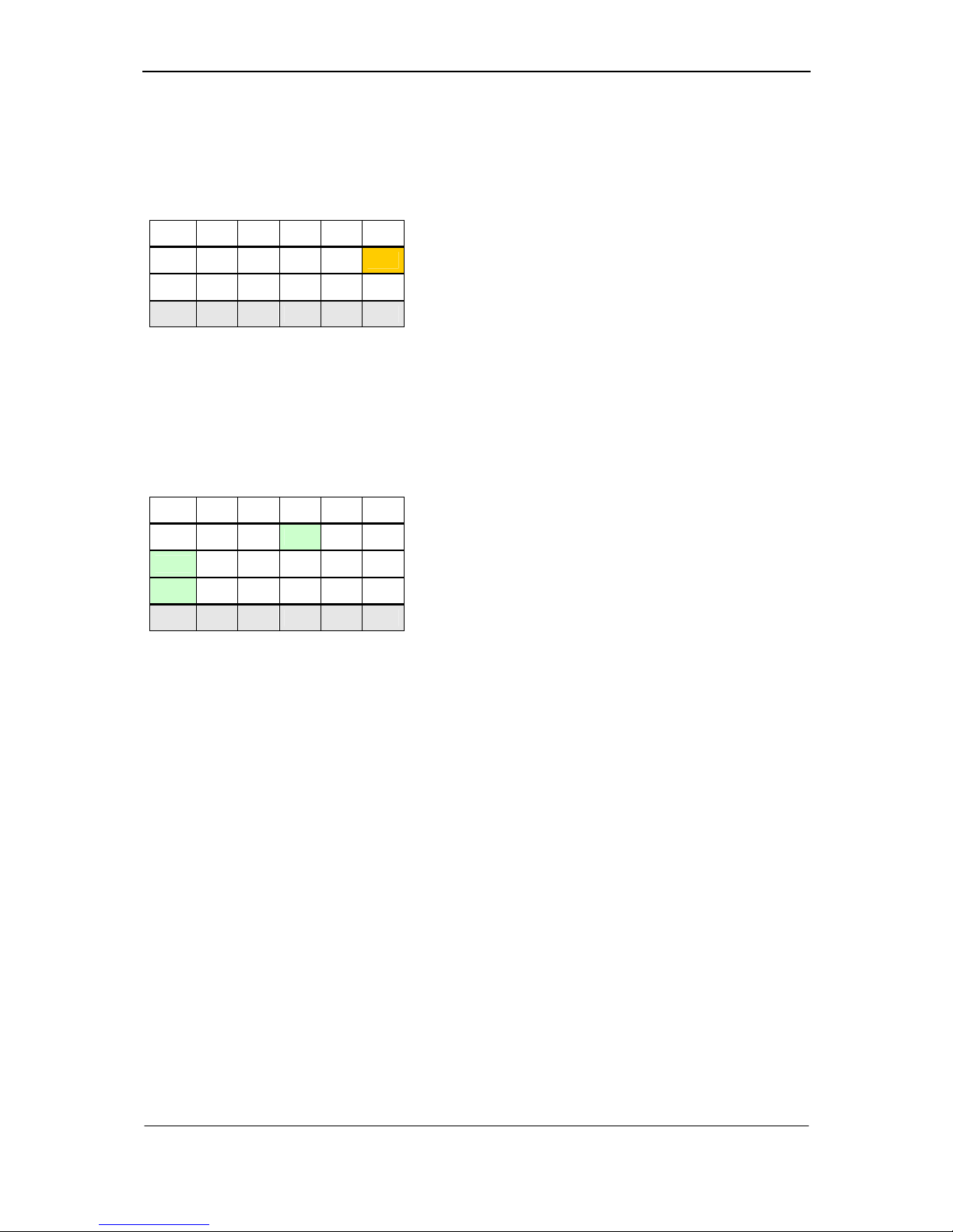
Assembly without masterkey wafers
Note! Only N pins are available as core pins for the lengths of 0, 1, 2, 3,
and for the lengths 4, 5, 6, 7 only AB pins are available.
Core pins
AB AB N N N AB
4 5 1 2 3 5
P1 P2 P3 P4 P5 P6
The core pins are applied at positions P1 – P6
depending on their lengths.
here: Position P1, P2 and P6: AB-pin;
Position P3, P4 and P5: N-pin
Assembly with masterkey wafers
Core pins
AB AB N N N AB
4 5 1 2 3 5
3 4 5
6 7
P1 P2 P3 P4 P5 P6
For assembly superstructures with masterkey
wafers the values of core pins are shown in the
upper cells. Assignment of pins is done similar
to assembly superstructures without masterkey
wafers. (see above)
Page 14
Sample lockings
12
Sample lockings without masterkey wafers
core
N AB N N N AB
0 4 1 2 2 6
FB N FB N N N
P1 P2 P3 P4 P5 P6
body
There is no restriction of the positions for core
pins. Therefore, an AB pin is applied at position
P6 depending on length.
Sample lockings with masterkey wafers
core
N AB AB AB AB N
3 4 7 5 6 3
5
FB FB N N N N
P1 P2 P3 P4 P5 P6
body
If two values of the body pins are equal (here:
length 5 on pos. P1 and P4), the FB body pin
must be inserted at the first possible position.
(here at pos. P1)
Page 15
Sigma Plus Assembly / Filling of cylinder body
13
Filling of cylinder body
Note! Depending on the length of the locking sides, two different core
lengths are applied: core 0 (509425) and core 5 (509426). Compared
with core 0, core 5 is 5 mm longer. In case of a cylinder which deviates
from the standard sizes, you must insert a core extension piece with cylinder pin, if necessary.
Double cylinder (standard)
ABABA
B
30 30 0 0 --- --35 30 5 0 --- --40 30 0 0 203643 --45 30 0 0 203644 --50 30 0 0 203645E --55 30 0 0 203643+44 --60 30 0 0 203643+45E --65 30 0 0 203644+45E --70 30 0 0 203647E --35 35 5 5 --- --40 35 0 5 203643 --45 35 0 5 203644 --50 35 0 5 203645E --55 35 0 5 203643+44 --60 35 0 5 203643+45E --65 35 0 5 203644+45E --40 40 0 0 203643 203643
45 40 0 0 203644 203643
50 40 0 0 203645E 203643
55 40 0 0 203643+44 203643
60 40 0 0 203643+45E 203643
45 45 0 0 203644 203644
50 45 0 0 203645E 203644
55 45 0 0 203643+44 203644
505000203645E
203645E
211590 211590
211590 211589
211591 211589
211592 211588
211589 211589
211590 211588
211591 211588
211593 211587
211588
211589 211588
211590 211587
211587
211592 211587
211587 211587
211587
211589 211587
Cylinder pin
standard
A B
--- --211587 --211588
211589
211590
211593
211588
211591
211588
Lock side Core
(mm)
Core extention
211591
211592
---
---
---
---
---
---
211594 ---
Page 16
Assembly / Filling of cylinder body
14
Double cylinder (double entry)
ABABA
B
30 30 0 0 --- --35 30 5 0 --- --40 30 0 0 203643 --45 30 0 0 203644 --50 30 0 0 203645E --55 30 0 0 203643+44 --60 30 0 0 203643+45E --65 30 0 0 203644+45E --70 30 0 0 203647E --35 35 5 5 --- --40 35 0 5 203643 --45 35 0 5 203644 --50 35 0 5 203645E --55 35 0 5 203643+44 --60 35 0 5 203643+45E --65 35 0 5 203644+45E --40 40 0 0 203643 203643
45 40 0 0 203644 203643
50 40 0 0 203645E 203643
55 40 0 0 203643+44 203643
60 40 0 0 203643+45E 203643
45 45 0 0 203644 203644
50 45 0 0 203645E 203644
55 45 0 0 203643+44 203644
505000203645E
203645E
Halve cylinder
511242 + 249759
511242 + 249759
511242 + 249759
511242 + 246291
511243
511243
511243
511243
511242
511242
511242
511243
511242
511242
511242
511242
511242 + 246291
---
---
---
---
---
---
---
---
---
511242 + 246293
511242 + 249759
511242 + 246291
511242 + 246292
511243
511242 + 249759
511242 + 246291
511242 + 246292
511242 + 246291
511242 + 246292
511242 + 246293
511242 + 246294
511242 + 246295
511242
511243
511242 + 249759
511242 + 246291
511242 + 246292
511242 + 246293
511242 + 246294
--511242
511243
511242 + 249759
A B
Cylinder pin
double entry
50 0 203645E
45 0 203644
40 0 203643
35 5 ---
30 0 ---
Length Core Core extention
(mm)
(mm)
Lock side Core Core extention
Page 17
Sigma Plus Assembly / Filling of cylinder body
15
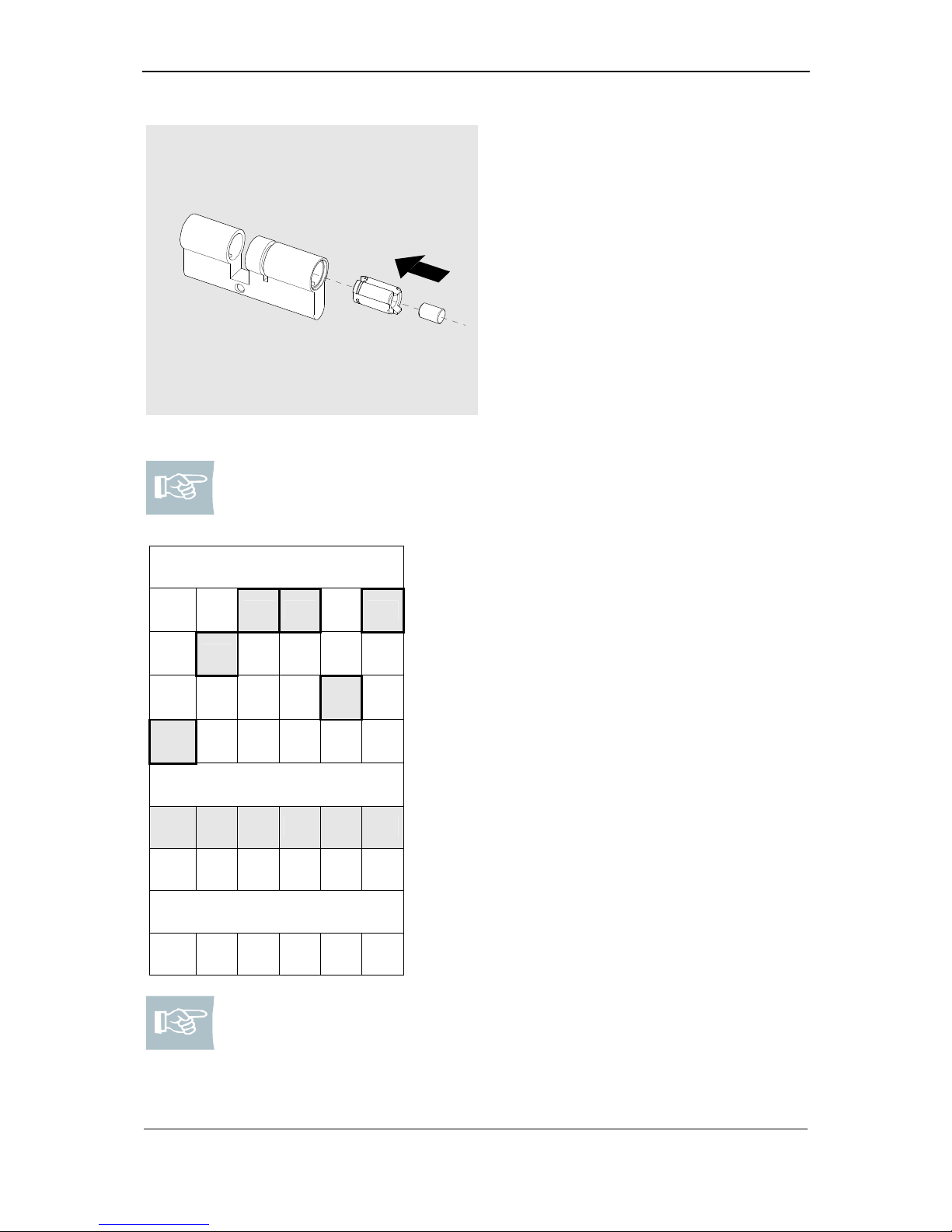
Fig. 2: Insert extension piece
1. If necessary please insert a core
extension piece with the appropriate
cylinder pin.
Note! Please hold the table of assembly superstructure ready. The body
pins are always stated in the last cell of a column. The following table of
assembly superstructure shows the body pins highlighted in grey.
Body pins
0 3 1 4 1 6
2 5
4 5
6
Example
N N FB FB N N
P1 P2 P3 P4 P5 P6
Type 382
H H H H H H
Body pin N:
0 – 3: 509264 112 = 5,5 mm
4 – 7: 509265 112 = 4,5 mm
Body pin FB:
0 – 3: 509268 112 = 5,5 mm
4 – 7: 509269 112 = 4,5 mm
Body pin H:
0: 509271 = 5,6 mm
1: 509271 = 5,6 mm
2: 509272 = 4,6 mm
3: 509272 = 4,6 mm
4: 509273 = 4,1 mm
5: 509273 = 4,1 mm
6: 509274 = 3,1 mm
7: 509274 = 3,1 mm
Note! When using hollow body pins (type 382) the corresponding N and
FB-body pins are inapplicable.
Page 18
Assembly / Filling of cylinder body
16
Caution! Position and number of pin types are prescribed:
FB-body pins: On each lock side two FB-body pins are inserted. FB-
pins may only be assembled at positions P1 – P5. The FB-body pins
have to be inserted on the positions with the lowest values (here P3
and P4).
N-body pin: On each lock side at least four N-body pins are inserted.
Note! The pins mentioned in the table, read from left to right, have to be
inserted on the follower from inside to outside.
inside
6
N
5
N
1
FB
4
FB
5
N
N
6
outside
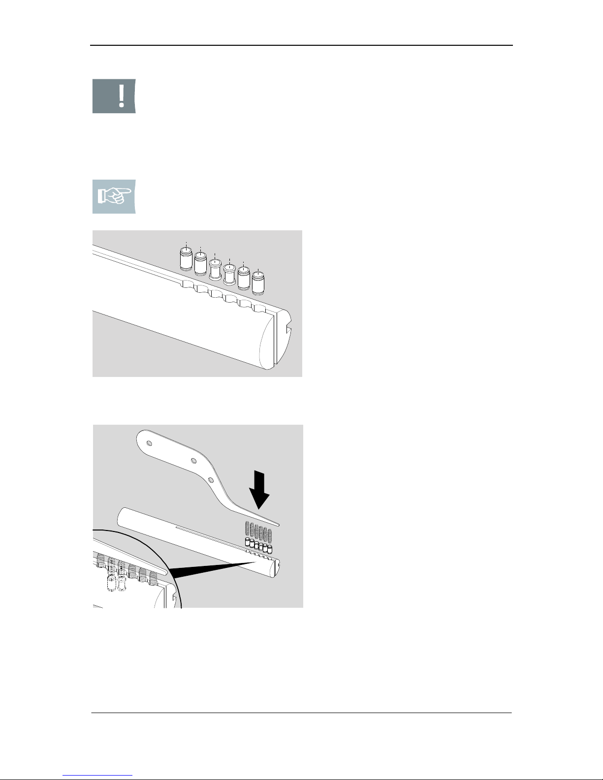
Fig. 3: Cylinder assembly superstructure
body pins
2. Please select the necessary body
pins.
Fig. 4: Filling of follower
3. Please insert the body pins into
follower correspondingly to the defined position.
4. Please apply compression springs
(242172) on the pins.
5. Using the loading knife, insert the
springs into the follower to such an
extent until the knife provides flush
fit with the follower.
Page 19
Sigma Plus Assembly / Filling of cylinder body
17
Caution! Material defects caused by improper insertion of the follower! If
the follower is inserted too far/not far enough into the cylinder body the
compression springs might be damaged.
Note! When mounting type KL you must assemble the long side,first.
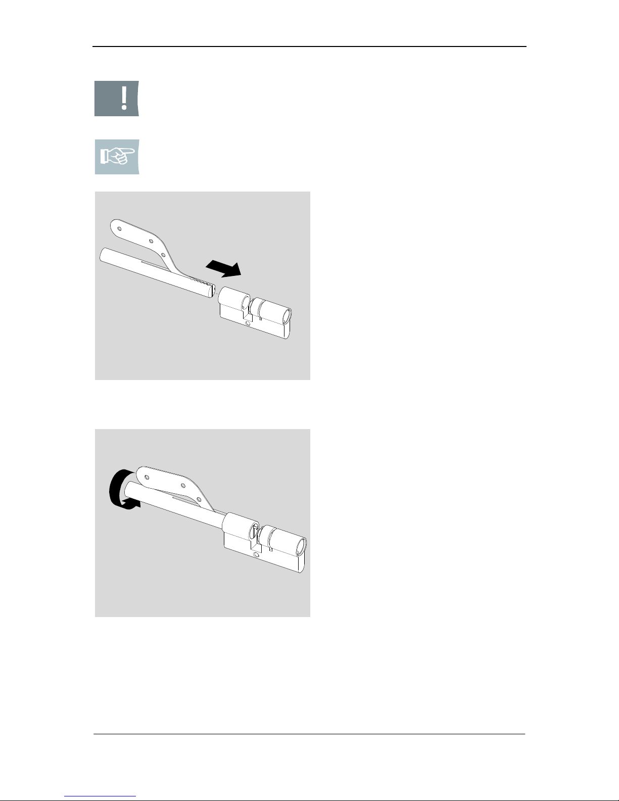
Fig. 5: Insert follower together with
loading knife into the cylinder body
6. Please insert the follower incl.
loading knife carefully into the cylinder body to such an extent until
the front edge of the follower provides approx. flush fit with the internal body edge (base length 30
mm) or the retainer ring device (extended version).
Springs and pins overlap the boring in
the cylinder body a little.
180°
Fig. 6: Turning follower together with load-
ing knife
7. Please turn follower incl. knife to
such an extent until the mounting
is positioned over the borings in
the cylinder body.
Page 20
Assembly / Filling of cylinder body
18
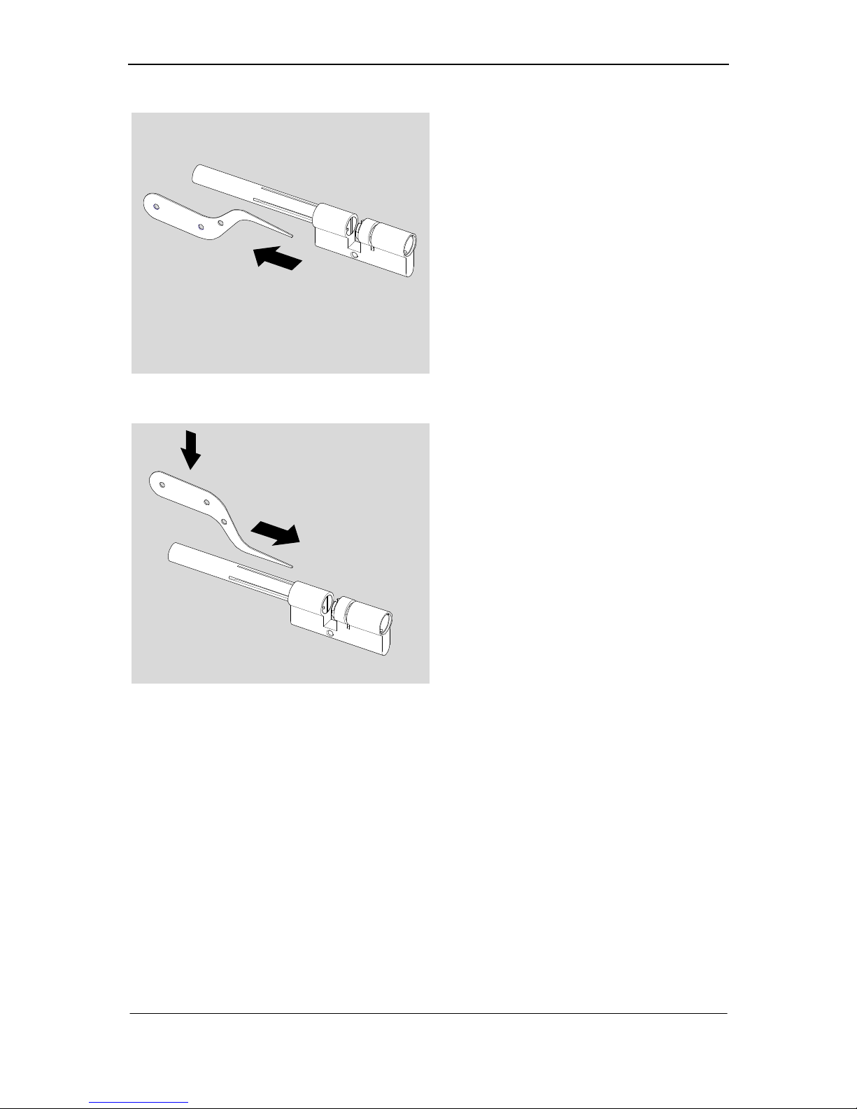
Fig. 7: Pulling out loading knife
8. Please pull out the loading knife.
9. Please turn follower carefully back
and forth until body pins are inserted into the respective core borings.
Fig. 8: Reinsertion of loading knife above
the pins
10. Please reinsert loading knife carefully above the pins.
Page 21
Sigma Plus Assembly / Filling of cylinder body
19
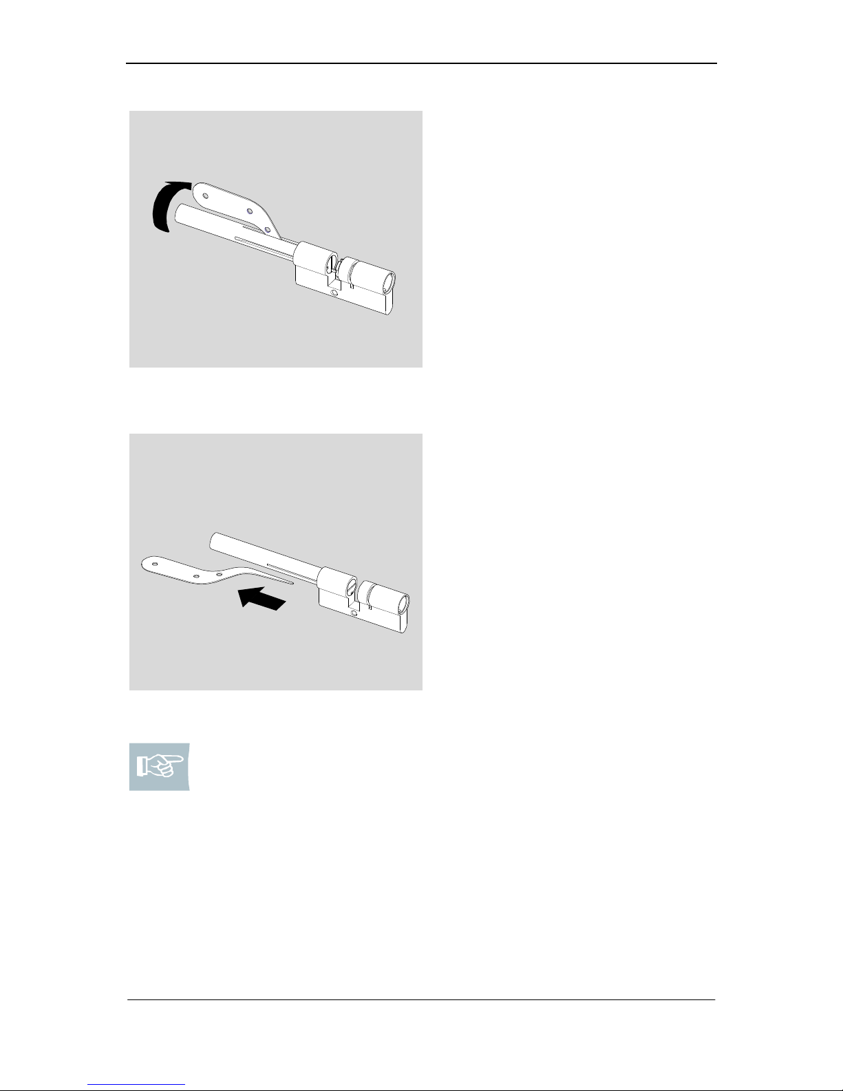
Fig. 9: Fixing of springs and pins in the
cylinder body
11. Please press the pins carefully
against the spring force into the
cylinder body until the follower may
be turned.
12. Please turn follower to such an
extent until the big groove is positioned over the borings in the cylinder body.
Fig. 10: Pull out loading knife
13. Please remove loading knife.
Note! If you install type KL (initially the longer side without assembly
bracket) or type 555 (without assembly bracket), you must leave the assembly bar in the cylinder body and go to page 21 and first fill the cylinder core.
If you assemble type 382 make sure you insert assembly clam from behind.
Page 22
Assembly / Filling of cylinder body
20
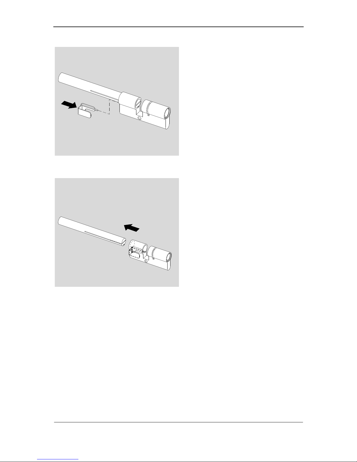
Fig. 11: Insert assembly clam
14. Please insert assembly clam accurately fitting.
Fig. 12: Pulling out follower
15. Please remove the follower without
pulling out the assembly clam. Now
the pins and springs are fixed within
the cylinder body.
16. Before continuing the assembly
please check whether all springs
and pins from the follower are fixed
in the body.
Page 23
Sigma Plus Assembly / Filling of cylinder core / Core pins
21
Filling of cylinder core
Note! The filling of cylinder core should be done on a soft pad, e.g. foam
rubber, in which you may press the core gently. Using a soft pad may
help you to insert the core into the body without problems. Thus the pins
do not fall out again. For assembling a cylinder with freewheel the core
511256 is needed.
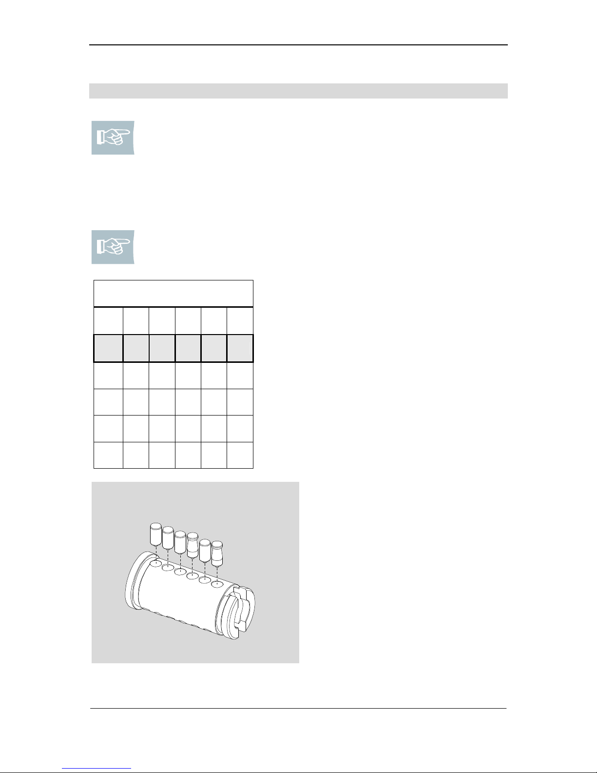
Core pins
Note! In the table of assembly superstructure you will find the core pins in
the upper row.
Core pins
N N N AB N AB
0 3 1 4 1 6
2 5
4
5
6
P1 P2 P3 P4 P5 P6
Core pin N: 0: 509254 112= 4,85 mm
1: 509255 112= 5,25 mm
2: 509256 112= 5,65 mm
3: 509257 112= 6,05 mm
Core pin AB 4: 509259 112 = 6,45 mm
5: 509260 112 = 6,85 mm
6: 509261 112 = 7,25 mm
7: 509262 112 = 7,65 mm
N
N
N
N
AB
AB
Fig. 13: Numbering of core pins
The pins mentioned in the table, read
from left to right, have to be inserted
from outside to inside on the cylinder
core.
1. Please insert core pins in the correct position.
Page 24
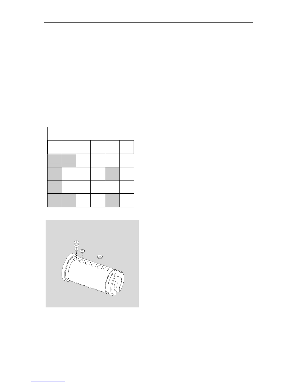
Assembly / Filling of cylinder core / Masterkey wafers
22
Masterkey wafers
MK wafers are used to permit locking variations in accordance with the specified
locking plan. A lock cylinder without MK wafers can only be locked by one key, while
a lock cylinder with MK wafers can be locked by different keys.
You can use the figures in the cylinder assembly fittings table to identify which and
how many MK wafers you must use. The figures that are listed vertically beneath a
core pin number (in grey) tell you which gradations are required for the relevant core
pin in the cylinder.
As can be seen from the table, a double gradation (MK gradation) is always allowed
for each pin position in locking systems. Once defined, the relevant even (0, 2, 4, 6)
or odd (1, 3, 5, 7) value for each pin position cannot be changed. The mounting direction of the MK wafers is not important.
MK wafers
0 3 1 4 1 6
2 5
4
5
6
P1 P2 P3 P4 P5 P6
Fig. 14: Masterkey wafers
MK wafers are
0.8 mm, 1.6 or 2.4 mm long.
One MK gradation corresponds to 0.8 mm.
Here:
You must place
3 MK wafers
(
2,4,6)
on the
first core pin (0).
As there is one MK gradation between
each of the figures (
0-2; 2-4; 4-6
), you
must insert
3 MK wafers
with a length of
0.8 mm
here.
On the second
core pin (3)
you must in-
sert
1 MK wafer
with a length of
0.8 mm
(one MK gradation
3-5
).
Do not place
any MK wafers
on the
third
(1) and fourth core pin (2)
in this case.
You must place
1 MK wafer 1.6 mm
long
on the
fifth core pin (1),
as there are two
MK gradations here (
1-5
).
Please do not add any
HS discs
to the
sixth core pin (6)
in this case.
Page 25
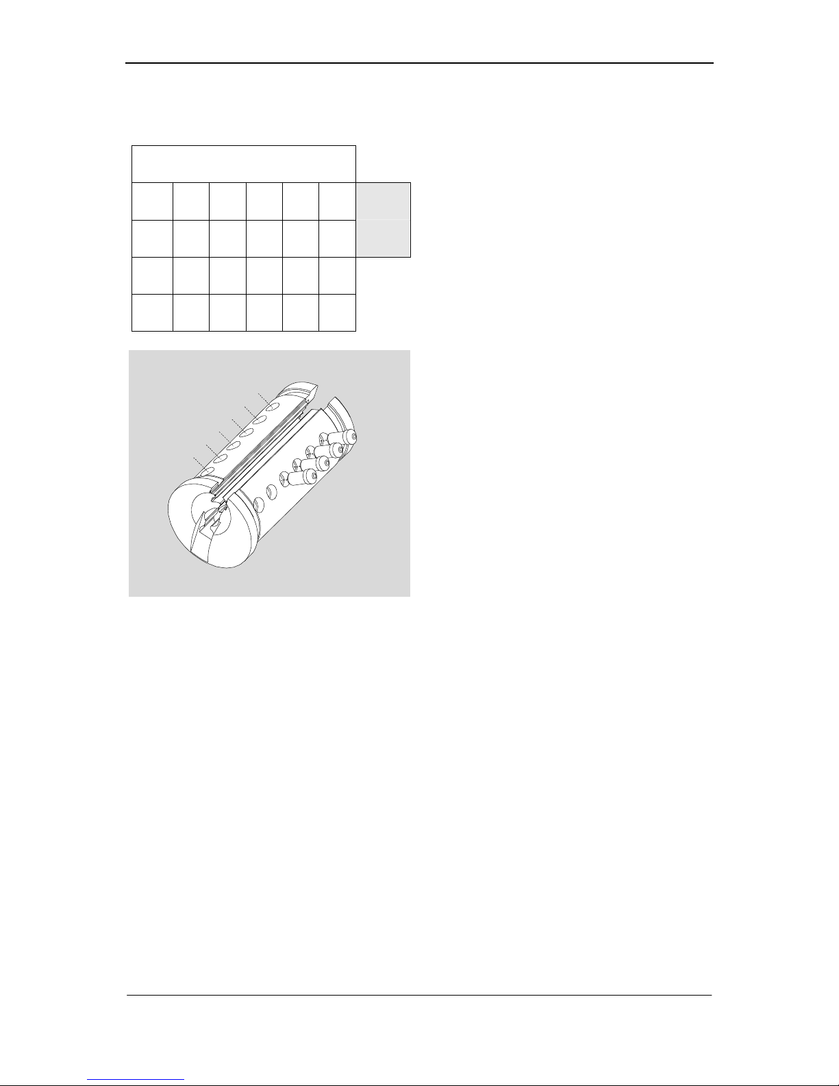
Sigma Plus Assembly / Filling of cylinder core / Profile control pins
23
Profile control pins
Profile control pins
0 3 1 4 1 6
Profile:
2 5 089B
4
5
6
Type and number of the profile control
pins can be identified from the specification of the profile in the assembly superstructure.
1
2
3
4
5
A
6
7
8
9
0
B
Fig. 15: Numbering of profile pins
Borings for profile control pins are numbered:
Left: 1, 2, 3, 4, 5, A
Right: 6, 7, 8, 9, 0, B
Sample: 0,8,9,B
1. Please insert the respective profile
control pins into the boring with tip
ahead and make sure they do not fall
out.
Page 26
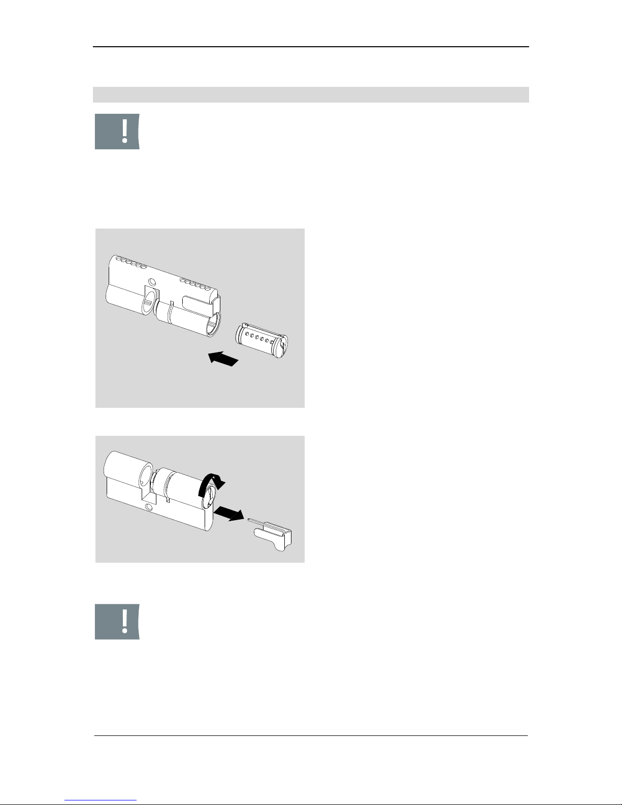
Assembly / Insertion of the cylinder core into cylinder body
24
Insertion of the cylinder core into cylinder body
Caution! Please make sure that the cylinder body is filled with the appropriate pins and springs before you insert the filled cylinder core into the
body. To prevent a fall out of core pins please use a soft pad. If necessary, rotate the body as illustrated in fig. 16 to avoid that the profile pins
will fall out of the core. When assembling
cylinder type KL
, please fol-
low the instructions beginning on page 34. When assembling
type 555
,
please follow the instructions beginning on page 39. When assembling
type 382
, please follow the instructions beginning on page 37.
Fig. 16: Core into body
1. Carefully insert the core with the key
channel upwards into the cylinder
body.
Fig. 17: Remove assembly clam and
turn core
2. Please protect the core from fall out
and remove the assembly clam.
3. Please turn the cylinder core until the
pins fall into the respective borings.
Caution! The cylinder core is not yet fixed by security rings. If you insert
the key the core may be pulled out from the body again and the pins will
fall out. In such an event core and body have to be completely re-filled.
Page 27
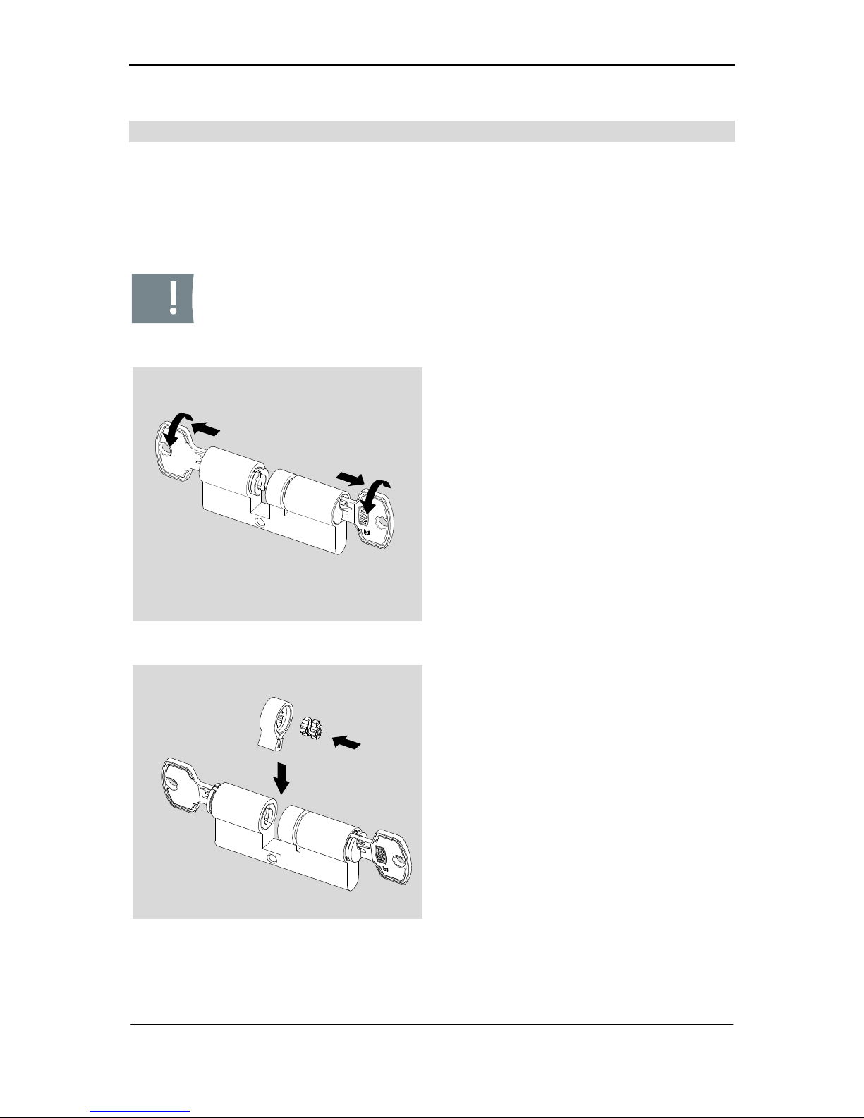
Sigma Plus Assembly / Type 333
25
Type 333
This chapter describes the assembly of the cam with coupling for type 333.
Requirements: 2 matching keys, 1 coupling (502154), cam (218228 008), 2 security
rings (202335F) for the cam, security ring (202335F) for each extended side (optional), 1 pliers (263629) for the cam, 1 pliers (261669) for the extension piece (optional).
Caution! The cylinder cores are not yet fixed by security rings. If you insert the keys the cores may be pulled out completely from body again
and the pins will fall out. In such an event cores and body have to be
completely re-filled.
Fig. 18: Placing cores
1. Please insert a matching key on both
sides.
2. Please turn key gently.
3. Please pull out cylinder cores to such
an extent until cores or core extension pieces provide a flush fit internally with the cylinder body.
Fig. 19: Insertion of cam with coupling
4. Please insert the coupling accurately
fitting into the cam.
5. Please insert the cam with coupling in
the centre of the cylinder body.
6. Please hold the cam in such a position that it provides flush fit with the
cylinder body at top and overlaps laterally a little at the bottom.
Page 28
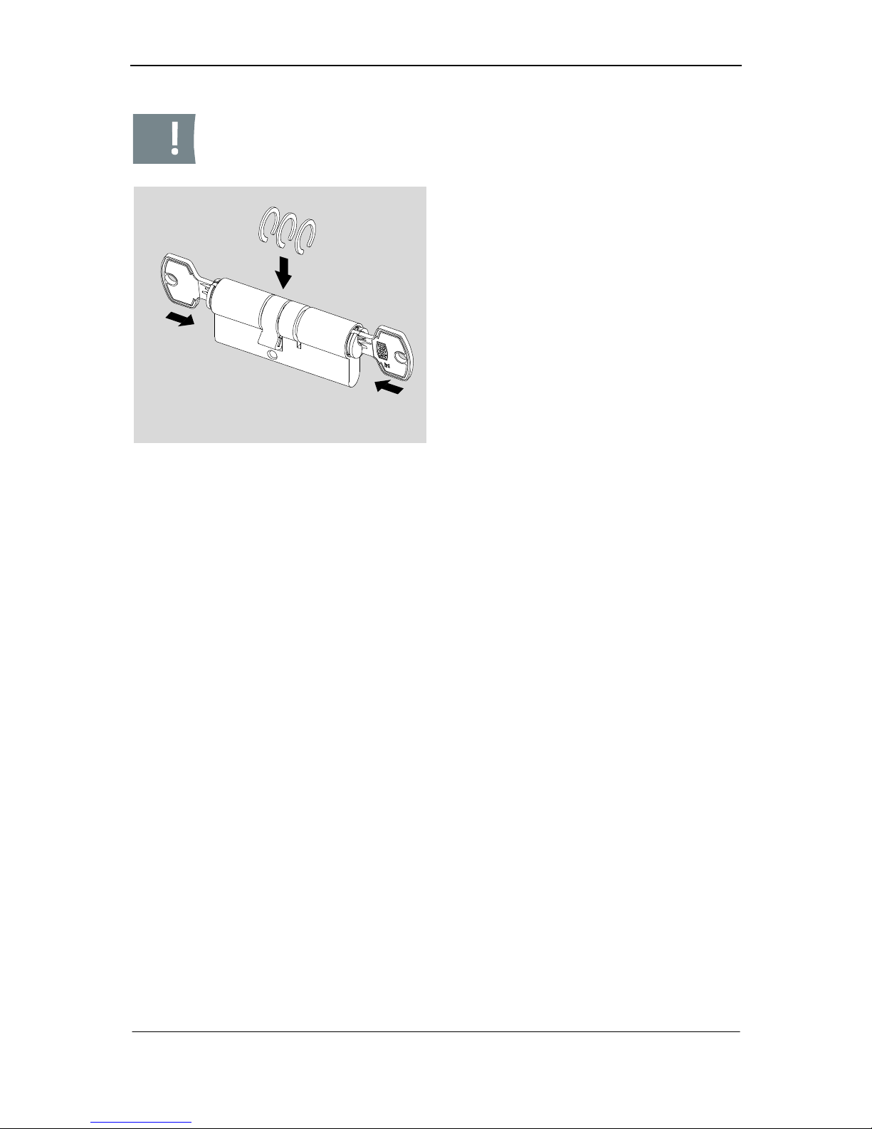
Assembly / Type 333
26
Caution! Please align security rings always in such a direction that the
flat side of the security rings point at the cam.
Fig. 20: Attaching security rings
7. Please push back the cores into the
cylinder body.
8. Please turn the cores into their initial
position and pull out keys while fastening the cores.
9. Please bend the security rings gently
apart.
10. Please insert the security rings in the
respective positions.
11. Please press the security rings together with the appropriate pincers.
Page 29
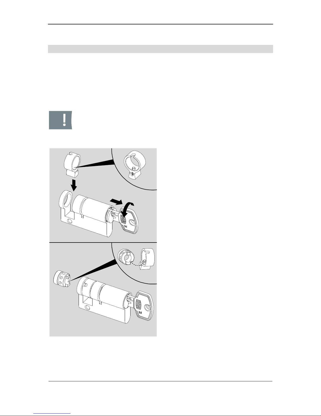
Sigma Plus Assembly / Type 333H
27
Type 333H
This chapter describes the assembly of the cam and the end piece as well as the positioning of the cam for type 333H.
Requirements: 1 matching key, 1 end piece (204217), 1 cam (218426 008), 2 security rings (202335F) for the cam, 1 security ring (202335F) for the extended side (optional), 1 pliers (263629) for the cam, 1 pliers (261669) for the extension piece (optional).
Caution! The cylinder core is not yet fixed by the security ring. If you insert the key the core may be pulled out completely from the body again
and the pins will fall out. In such an event core and body have to be
completely re-filled.
!
!
Fig. 21: Insertion of cam and end piece
1. Please insert a matching key.
2. Please turn key gently.
3. Please pull out the cylinder cores to
such an extent until core or core extension piece provides a flush fit internally with the cylinder body.
4. Please insert the cam into the cylinder body in such a way that the opening with the spring pin points towards
the end piece.
5. Please hold the cam in such a position that it provides flush fit with the
cylinder body at top and overlaps laterally a little at the bottom.
6. Please push the core back into the
cylinder body.
7. Please turn the core into its initial position and pull out the key while fastening the core.
8. Please insert the end piece into the
cylinder body in such a way the
spring pin of the cam slides over the
chamfered part of the end piece.
Page 30
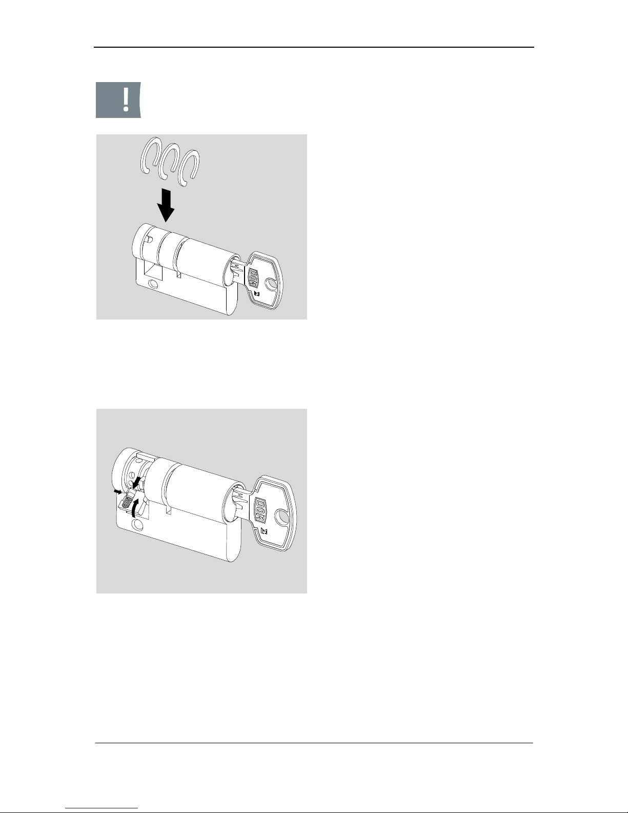
Assembly / Type 333H
28
Caution! Please always align security rings in such a position that the flat
side of the security rings points towards the cam.
Fig. 22: Attaching security rings
9. Please push the core back into the
cylinder body.
10. Please turn the core into its initial position and pull out the key while fastening the core.
11. Please bend security rings gently
apart.
12. Please insert security rings into the
respective positions.
13. Please press the security rings together with the appropriate pincers.
Adjusting cam
The cam may be adjusted in eight different positions as required.
Fig. 23: Adjustment of cam
14. Please pull down the spring pin of the
cam using a blunt object.
15. Please align cam at the required position.
Page 31
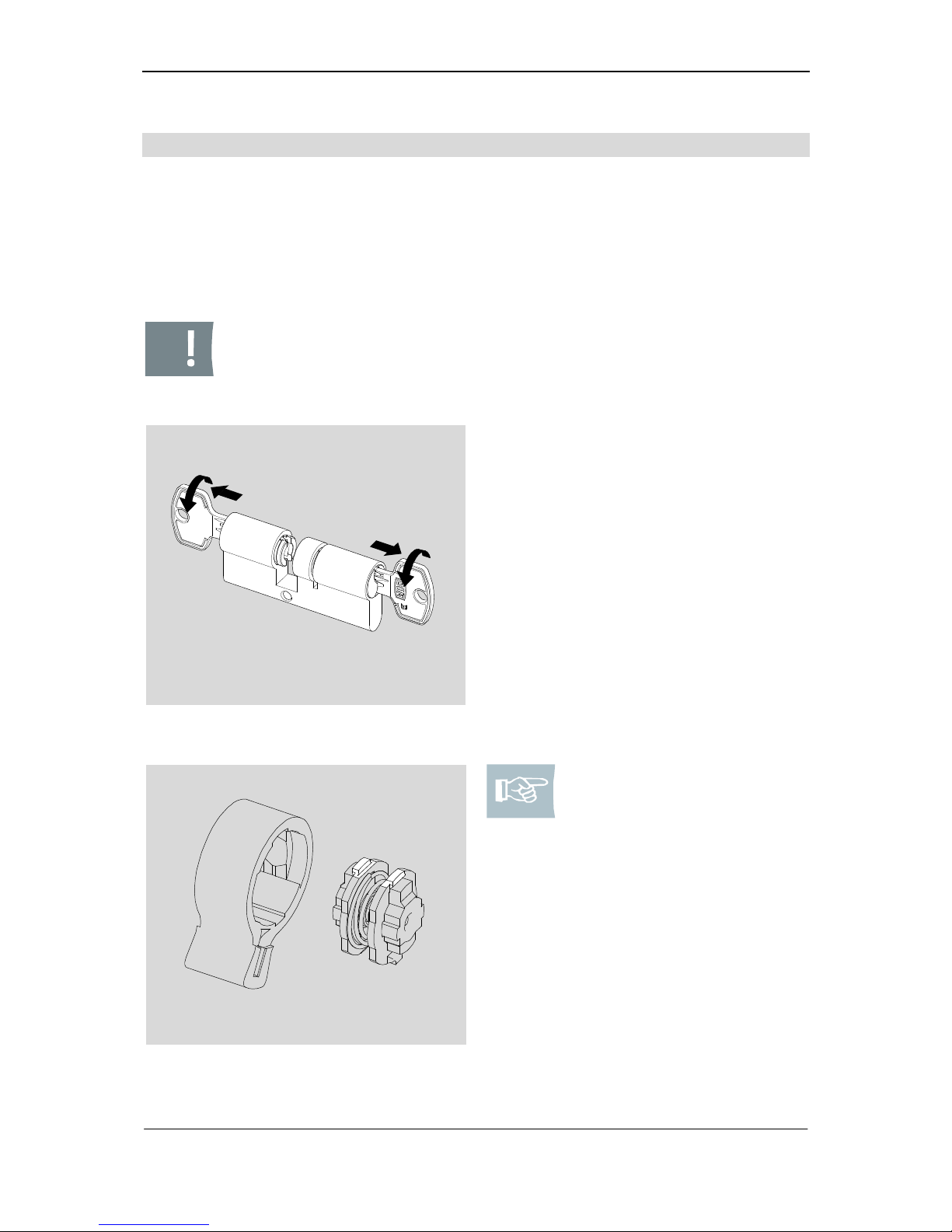
Sigma Plus Assembly / Type 333T
29
Type 333T
This chapter describes the assembly of cam with coupling for type 333T. (Lockable
with key inserted on both sides)
Requirements: 2 matching keys, 1 coupling (235860), 1 cam (235855 008), 2 security
rings (202335F) for the cam, security ring (202335F) for each extended side (optional), 1 pliers (263629) for the cam, 1 pliers (261669) for the extension piece (optional).
Caution! The cylinder cores are not yet fixed by security rings. If you insert the keys the cores may be pulled out completely from body again
and the pins will fall out. In such an event cores and body have to be
completely re-filled.
Fig. 24: Positioning cores
1. Please insert a matching key on both
sides.
2. Please turn the keys gently.
3. Please pull out cylinder cores to such
an extent until cores or core extension pieces in the cam groove provide
a flush fit with the cylinder body.
Fig. 25: Adjust coupling
Note! When assembling the
coupling (double entry) in
the lock stud you must take
care that both discs of the
coupling are congruent with
each other. At first, the coupling is inserted into the lock
stud together with the copper-coloured discs. The flat
side of the disc must point
upwards.
Page 32
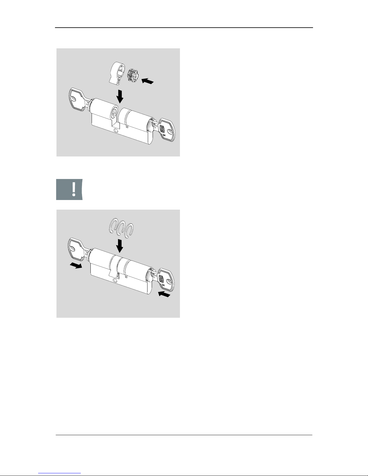
Assembly / Type 333T
30
Fig. 26: Insertion of cam and coupling
4. Please insert the coupling accurately
fitting into the cam.
5. Please insert the cam with the coupling into the centre of the cylinder
body.
6. Please hold the cam in such a position that it provides flush fit with the
cylinder body at top and overlaps laterally a little at the bottom.
Caution! Please always align security rings in such a way that the flat
side of the security rings point towards the cam.
Fig. 27: Insertion of security rings
7. Please push cores back into the cylinder body.
8. Please turn the cores into their initial
position and pull out the keys by fastening the cores.
9. Please bend security rings gently
apart.
10. Please insert security rings into the
respective positions.
11. Please press the security rings together with the appropriate pincers.
Page 33
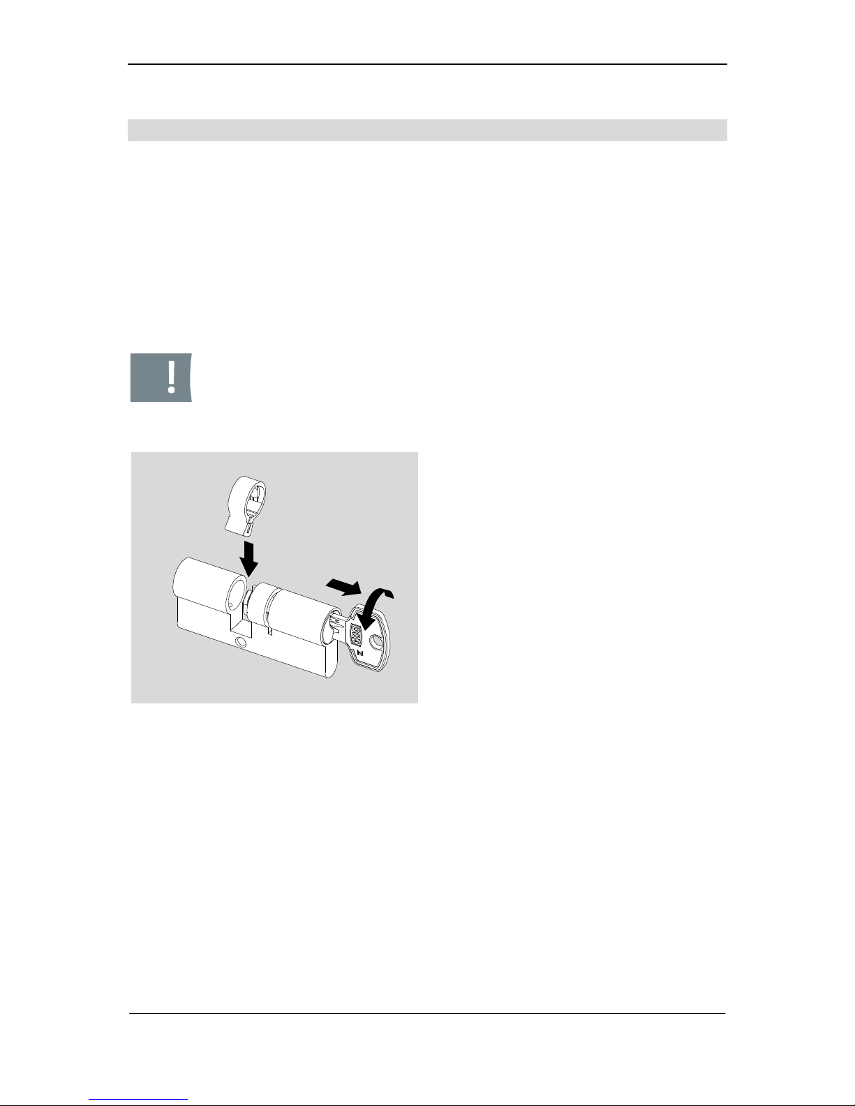
Sigma Plus Assembly / Type 333K
31
Type 333K
This chapter describes the assembly of the cam with stud for the type 333K. Type KL
with knob must be assembled in the same way.
Requirements: 1 matching key, 1 cam (235855), 2 security rings (202335F) for the
cam, 1 security ring (202335F) for each extended side (optional), 1 stud axis (depending on the length), 1 spiral pin (099434), 1 coupling (220895), 1 carrier plate
(220897F 002), 1 cone pin (236497) 1 compression spring (215230), 1 pliers
(261669) for the cam, 1 pliers (261669) for the extension piece (optional).
When mounting type KL with knob, you need the following:
1 cam (509293 008) and 1 stud axis (509393).
Caution! The cylinder core is not yet fixed by the security ring. If you insert the key the core may be pulled out completely from body again and
the pins will fall out. In such an event core and body have to be completely re-filled.
Fig. 28: Insertion of cam
1. Please insert a proper key.
2. Please turn key gently.
3. Please pull out the cylinder core to
such an extent until the core or the
core extension piece provides a flush
fit internally with the cylinder body.
4. Please insert cam into the cylinder
body.
Page 34
Assembly / Type 333K
32
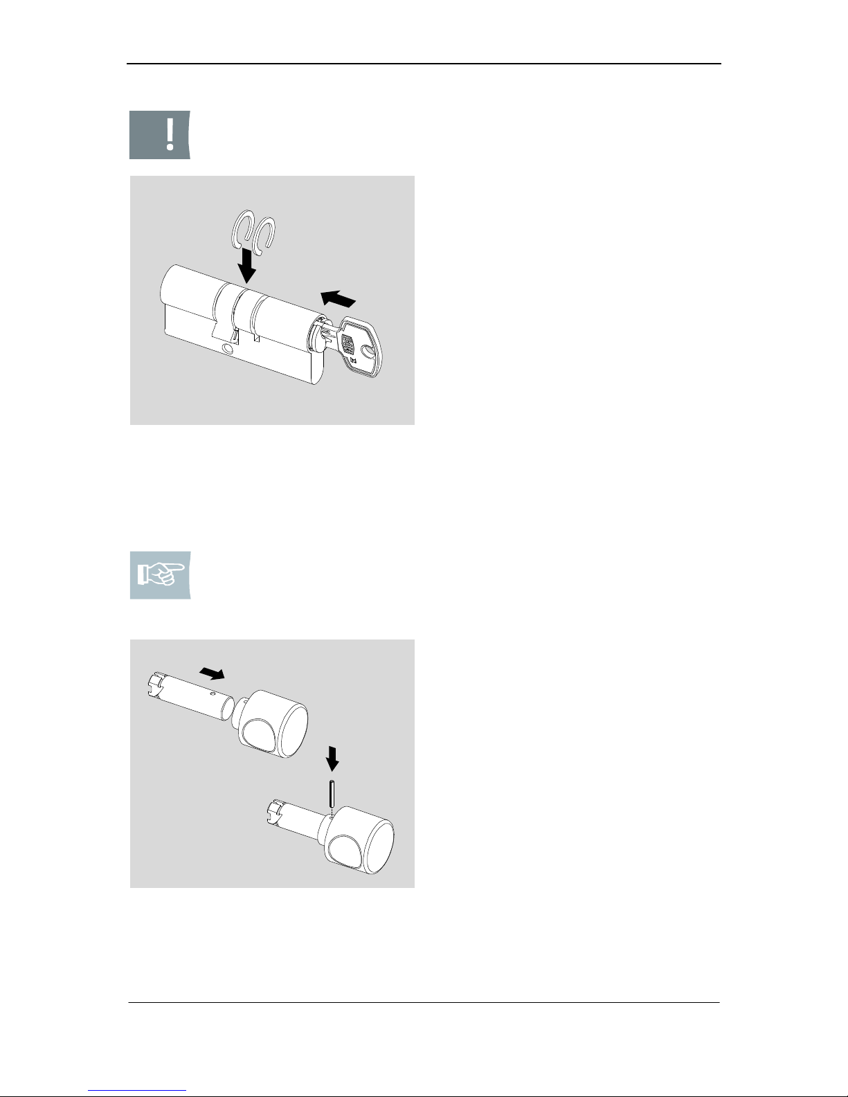
Caution! Please always align security rings so that the flat side of the security rings points towards the cam.
Fig. 29:
Attaching security rings for core
(with extension piece)
5. Please hold the cam in such a position that it provides flush fit with the
cylinder body at top and overlaps laterally a little at the bottom.
6. Please push the core back into the
cylinder body.
7. Please turn the core into its initial position and pull out the key while fastening the core.
8. Please bend the security rings gently
apart.
9. Please insert security rings in the respective positions.
10. Please protect the core against fall
out.
11. Please press security rings together
with the appropriate pincers.
Note! If you are not sure about the boring to fix the stud on a stud axis
with several borings, please measure directly at the cylinder body.
Please insert axis without stud into the cylinder body. Please use the first
boring you see that is outside.
Fig. 30: Fixing of knob
12. Please spray knob axis gently with
the service spray provided by DOM.
13. Please insert knob axis in such a way
that the boring on the axis provides
flush fit with the boring in the knob.
14. Please insert the spiral pin into the
boring of the knob.
15. Please beat the spiral pin completely
into the boring without producing any
damages of the knob.
Page 35
Sigma Plus Assembly / Type 333K
33
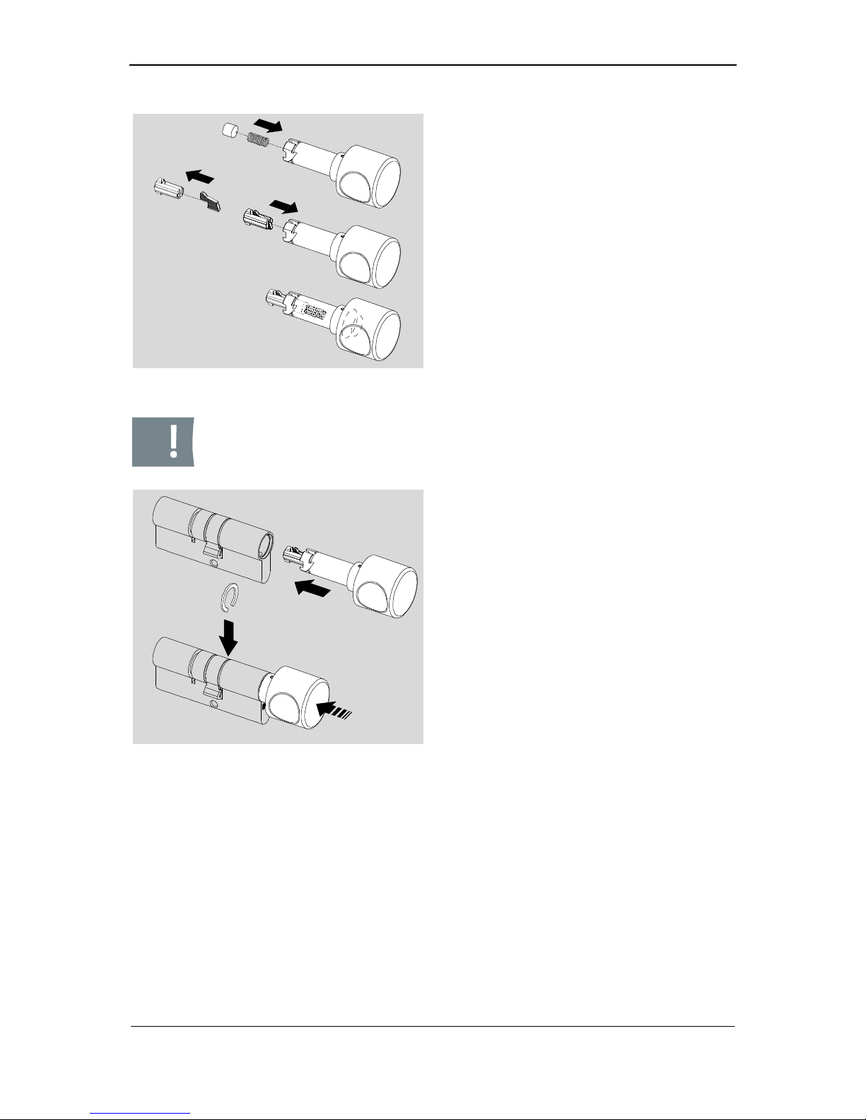
Fig. 31: Filling of knob axis
16. Please insert the compression spring
first into the knob axis before you insert the cone pin.
17. Please insert the carrier plate into the
coupling now.
18. Please carefully insert coupling and
carrier plate into the knob axis.
Caution! Please always align the security rings so that the flat side of the
security rings points towards the cam.
Fig. 32: Insertion of knob axis
19. Please insert the filled stud axis into
the cylinder body.
20. Please protect the stud against fall
out.
21. Please bend the security ring gently
apart.
22. Please insert the security ring in the
respective position.
23. Please press the security ring together with the appropriate pincers.
Page 36
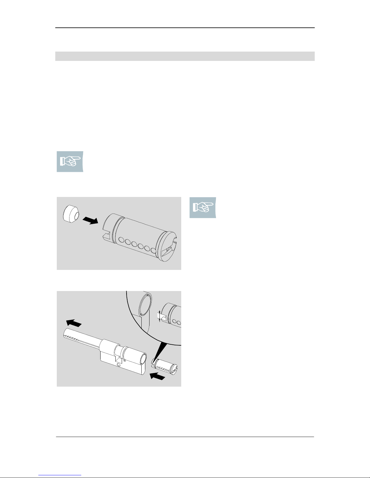
Assembly / Type 333KL
34
Type 333KL
This chapter describes the assembly of the cylinder cores and the lock stud with
coupling for type 333KL. When assembling type KL with knob, please follow the instructions on page 31.
Requirements: 2 filled cylinder cores, 1 follower (266009), 1 coupling (standard
502154 or double entry 235860), 1 cam (standard 509292 008 or double entry
509293 008), 1 cylinder pin (27/35: standard 207102 or double entry 510598 011;
27/40: standard 510361 or double entry 510599 011), 1 security ring (202335F) for
the longer side, 1 security ring (214340F) for the shorter side, 1 pliers (263629) for
the cam, 1 pliers (265776) for the security ring (214340F).
Note! First, you must assemble the long side. You have already filled the
cylinder core and inserted the cylinder pin (standard 207102 or double
entry 510598 011) into the cylinder core. When assembling an extended
cylinder (27/40), you have already inserted the cylinder pin (standard
510361 or double entry 510599 011).
Fig. 33: Cylinder pin double entry 27/35
Note! Cylinder 27/35 double
entry: Insert the cylinder pin
510598 011 into the core,
the flat side pointing in the
direction of the coupling.
4 mm
Fig. 34: Insert core on the long side
1. Apply the cylinder core to the as-
sembly bar in a way that the larger
cut-out (4 mm) shows to the front.
2. Please insert the cylinder core into
the cylinder body pressing out the
assembly bar backwards.
3. Leave the cylinder core in this posi-
tion (do not rotate).
Page 37
Sigma Plus Assembly / Type 333KL
35
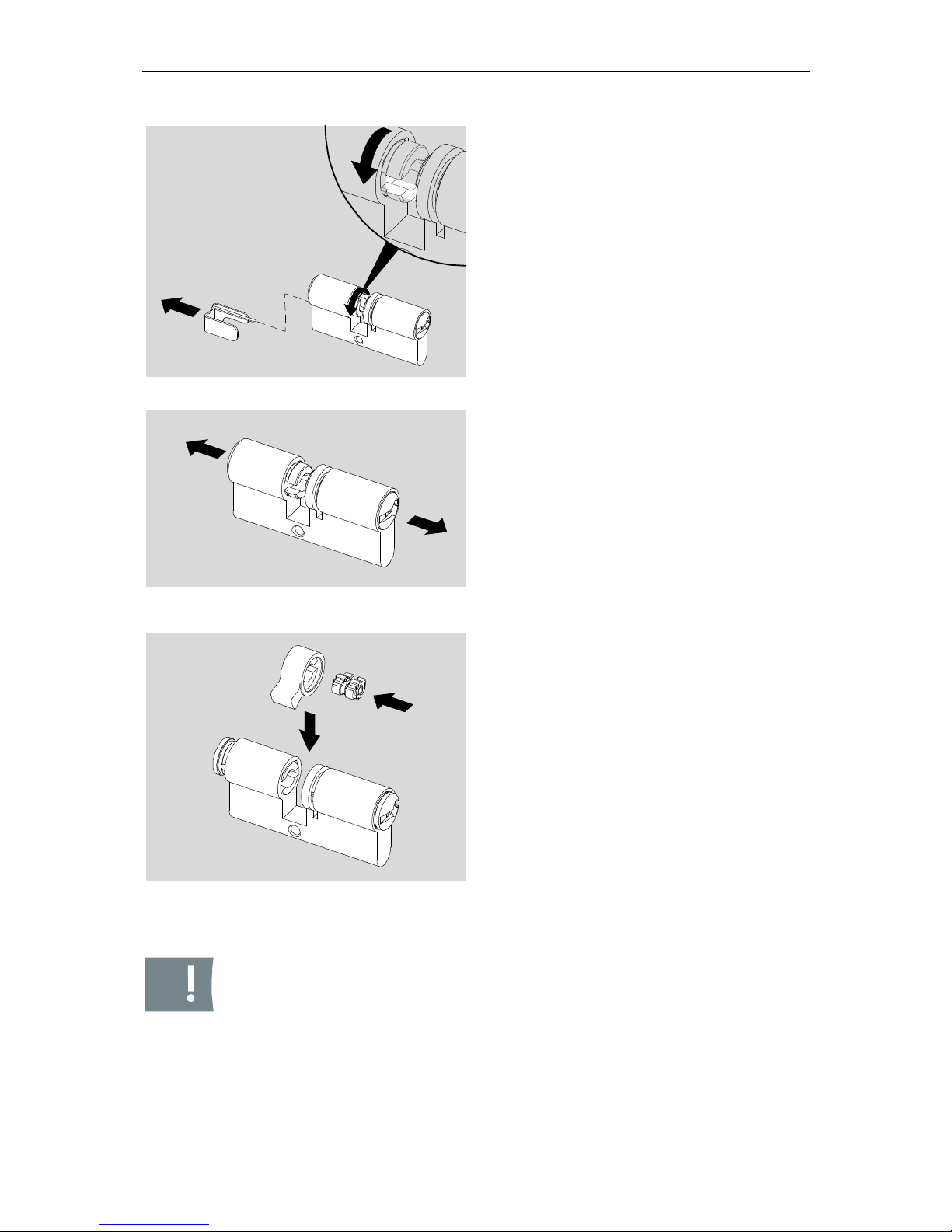
Fig. 35: Rotate short core
4. Now fill the short side of the body according to the instructions on page 13
and insert the filled core according to
the instructions on page 24ff.
5. Remove the assembly bracket.
6. Now adjust the short core in a way
that the larger cut-out is flush with the
cut-out of the long core.
Fig. 36: Positioning cores
7. Please pull out cylinder cores to such
an extent until cores in the cam
groove provide a flush fit with the cylinder body.
Fig. 37: Insertion of cam
8. Please insert the coupling accurately
fitting into the cam.
9. Please insert the cam with the coupling into the centre of the cylinder
body.
10. Please hold the cam in such a position that it provides flush fit with the
cylinder body at top and overlaps laterally a little at the bottom.
11. Please push cores back into the cylinder body.
12. Rotate the lock stud until the coupling
engages with the lock stud.
Caution! Please always align security rings in such a way that the flat
side of the security rings point towards the cam.
Page 38
Assembly / Type 333KL
36
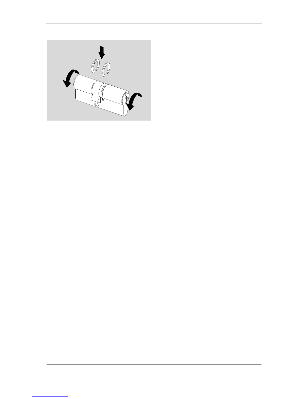
Fig. 38: Insertion of security rings
13. After having assembled the lock stud,
please rotate the long core counterclockwise and the short core clockwise into removing position.
14. Please bend security rings gently
apart.
15. Insert the security ring (202335F) at
the longer side.
16. Insert the security ring (214340F) at
the shorter side in a way that the stud
will engage with the groove (4 mm).
17. Please press the security rings together with the appropriate pincers.
Page 39
Sigma Plus Assembly / Type 382
37
Type 382
This chapter describes the assembly of the knurled pin and the lever.
Requirements: 1 filled cylinder core with assembly bushing (266674), 1 matching
key, 1 lever (200013), 1 knurled pin (242081), 2 hexagon nuts core (201306), 1
hexagon nut body (201320), 2 open-jawed wrenches SW14 and SW30.
Note! You have already filled the core and an assembly bushing secures
the core pins. The assembly bracket is still at the body and secures the
body pins.
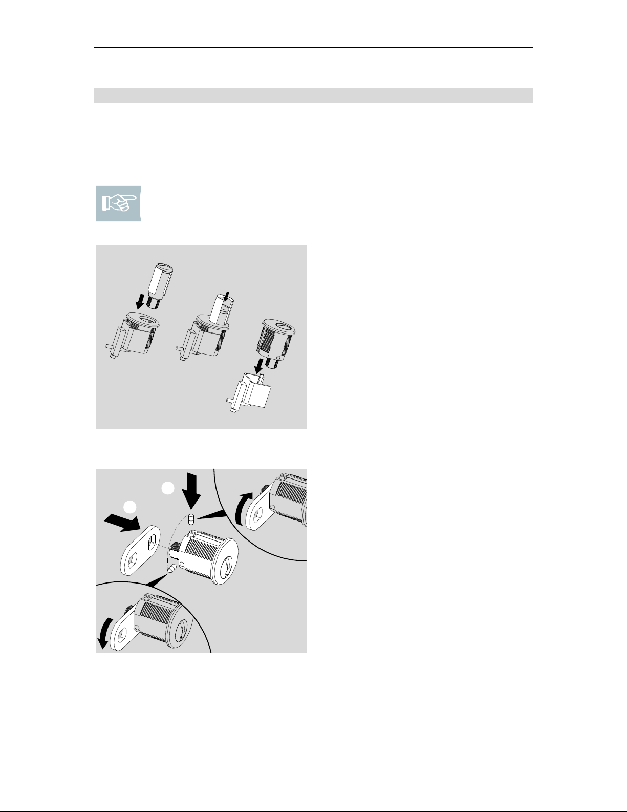
Fig. 39: Insert core
1. Apply the core to the cylinder body.
2. Insert the cylinder core into the cylinder body that it is precisely fitting. The
assembly bushing is stripped off.
3. Remove the assembly bracket and
rotate the cylinder core clockwise until the pins fall into the provided bores.
A
B
Fig. 40: Adjust closing direction and
attach lever
4. Please set the required closing
direction with the knurled pin.
closing clockwise
: Please insert the
knurled pin into the vertical boring
above.
closing anti-clockwise
: Please
insert the knurled pin on the left side
whilst facing the DOM-logo.
5. Please push the lever on the cylinder
core from behind in the position
required.
Page 40
Assembly / Type 382
38
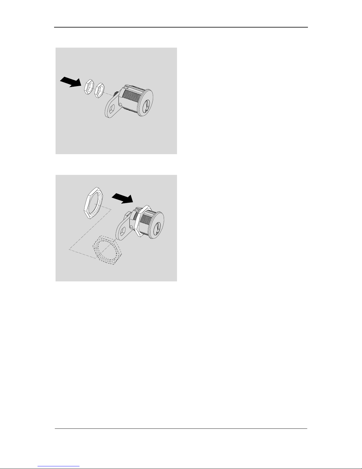
Fig. 41: Fastening and fixing lever
6. Please fasten the lever with a hexagonal nut SW 14 (hand-tight).
7. Please fix the hexagonal nut by a
second hexagonal nut SW 14 (handtight).
Fig. 42: Assembling cylinder
8. Please insert the cylinder at the respective position and fasten it with a
hexagonal nut SW 30 (hand-tight)
Page 41
Sigma Plus Assembly / Type 555
39
Type 555
This chapter describes the final assembly of the body as well as the assembly of the
engaging bar.
Requirements: 1 filled cylinder core with assembly bushing (266674), 1 follower
(260009), 1 rosette 555P (233617); 1 rosette 555R: (200928), 1 barrel 555R
(201695), 1 compression spring (202076), 1 pin (227698), 1 engaging bar (227690),
1 engaging disc (227603), 1 round nut (237599), 1 attaching plate (201624), 2 countersunk screws (200927),
Note! You did already fill the core and An assembly bushing secures the
core pins. The follower is still inside the cylinder body. An assembly with
assembly clam cannot be performed due to the cylinder form.
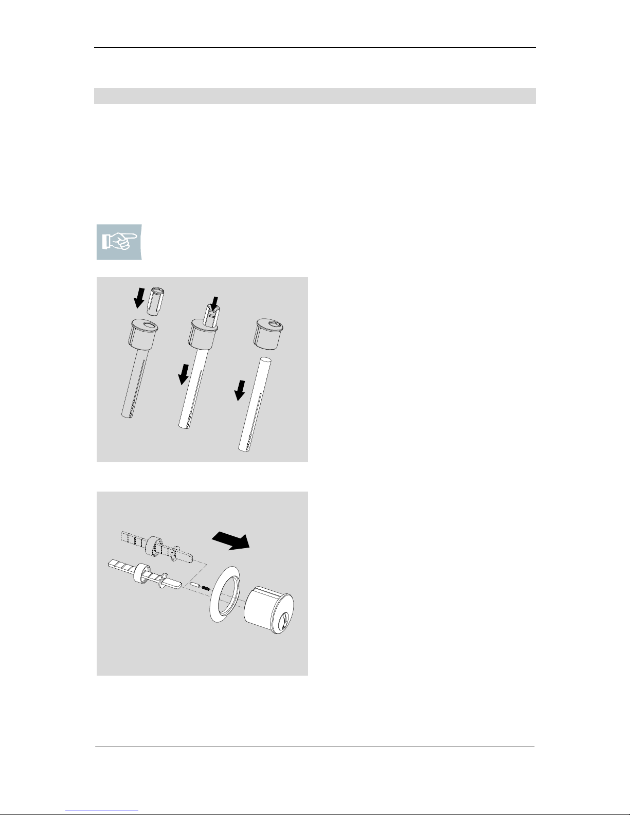
Fig. 43: Insert core
1. Please put the threaded side of the
cylinder core into position on the follower.
2. Insert the cylinder core into the cylinder body. The assembly bushing is
stripped off and the assembly bar is
pressed out backwards.
3. Please turn the cylinder core until the
body pins will be pushed into the respective borings.
Fig. 44: Fastening engaging bar
4. Please push the rosette (with barrel
at 555R) over the cylinder body.
5. Please insert the compressing spring
and the pin into the boring of the cylinder core.
6. Please push the engaging disc and
the round nut on the engaging bar.
7. Please fasten the engaging bar
using a round nut at the cylinder core
either horizontally or vertically depending on its use. The pin will be
pushed into the recess of the engaging disk by the compression spring.
Page 42
Assembly / Type 555
40
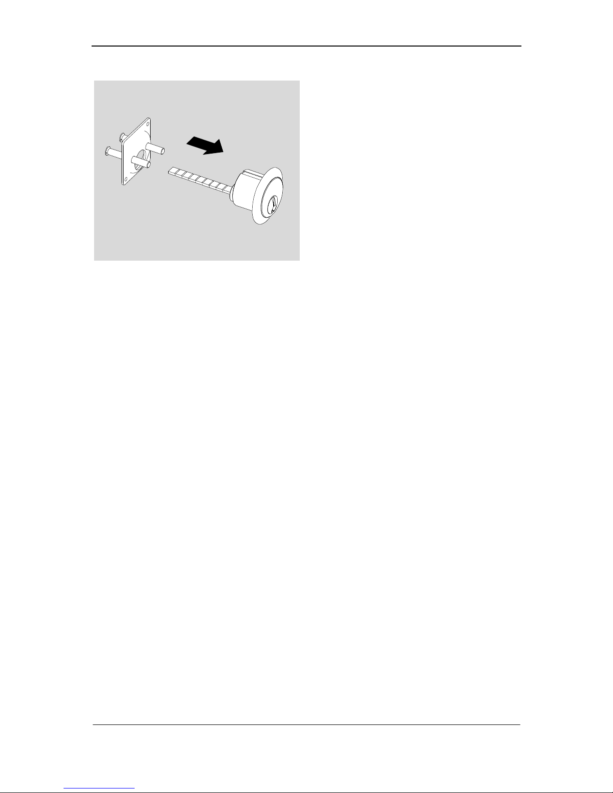
Fig. 45: Assembling cylinder
8. Please insert cylinder body in the respective position and fasten it to the
attaching plate by using countersunk
screws (hand-tight).
Page 43
Sigma Plus Assembly / Type 777
41
Type 777
This chapter describes the final assembly of the padlock.
Requirements: 1 matching key, 1 engaging piece (229303), 1 bolt (217102), 1
screwdriver for recessed head screws.
Note! You did already insert the core in the body and fastened it with a
security ring (202335F).
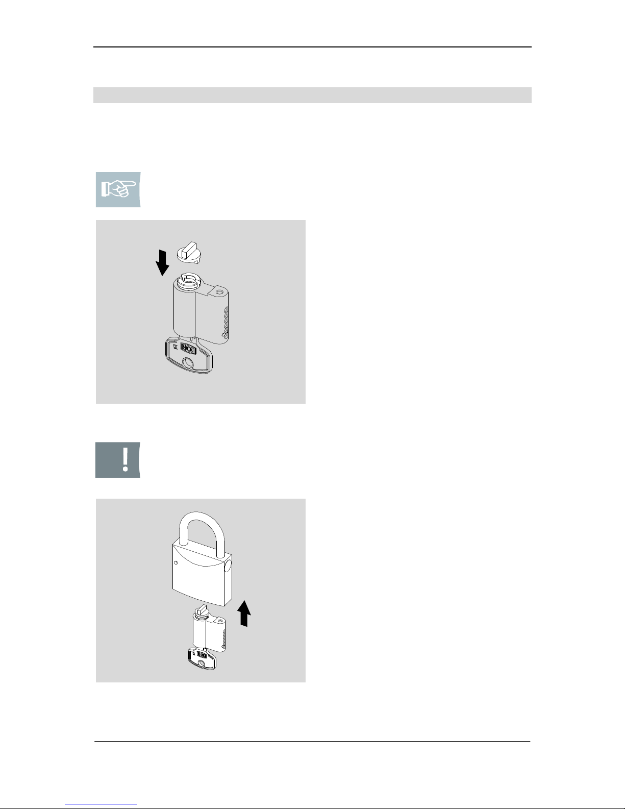
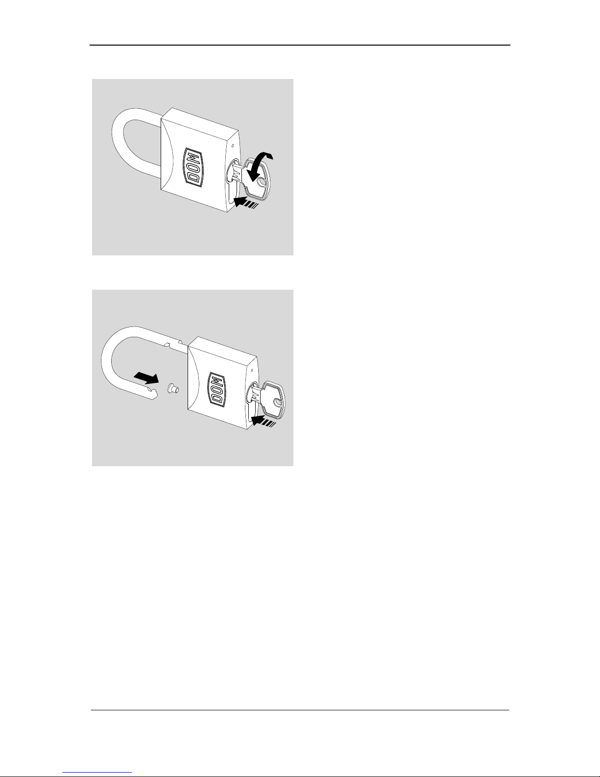
Fig. 46: Positioning engaging piece
1. Please insert a matching key into the
cylinder core.
2. Please hold the core body as shown
in Fig. 45 and insert engaging piece
accurately fitting from behind into the
cylinder core.
Caution! The shackle always has to be closed if the core body is not inside the padlock. Otherwise the fixed spring elements may get disengaged and have to be re-assembled.
Fig. 47: Insert lock barrel
3. Please insert the core body into the
padlock with closed shackle.
Page 44
Assembly / Type 777
42
Fig. 48: Positioning lock barrel
4. Please move the key gently until the
lock barrel can be inserted completely
into the padlock.
5. Please permanently protect the lock
barrel against fall out and open the
shackle.
Fig. 49: Fastening lock barrel
6. Please keep protecting the lock barrel
against fall out.
7. Please put on the screw in the
shackle opening and fix the lock barrel with the screw (hand-tight).
Page 45

Sigma Plus Maintenance/Storage/Disposal
43
Maintenance
Please refresh lubrication of the lock cylinder periodically using DOM service-spray.
Storage/Maintenance
If the DOM locking cylinders or several components are to be stored for a prolonged
period of time before assembly or after use, store it dry and dust-free in the original
packaging.
Caution! Material defect because of improper lubricants! Please periodically lubricate and maintain the lock cylinder using DOM service-spray
exclusively.
Disposal
Please note that DOM locking cylinders partially consists of high quality metallic
components that have to be disposed of in a specific way. Always comply with all
customary provisions for the protection of the environment when disposing of them.
You can also send the components of your DOM locking cylinder back to the manufacturer.
Page 46

Technical data
44
Technical data Sigma Plus
•
6 spring mounted, massive tumblers in axial order at each lock side
•
Consisting of 12 sectionally graded core and body pins
•
Massive pin tumblers with a minimum diameter of 2.7 mm, made of hard bronze /
steel, hardened and chemically nickel-plated
•
Smallest lock unit with the pin tumblers, massive solid pin with a minimum height
of 0.8 mm
•
Waisted core and body pins
•
Truncated conical pin heads for securing the block and lock function of the clo-
sure mechanism
•
One-piece cylinder body made of massive brass, surface electro-plated in sev-
eral steps, high protection against corrosion, optional modular design
•
Cylinder core made of massive brass, one-piece, with a minimum diameter of 13
mm
•
Curved core head with guide funnel and core head groove for the positive trans-
mission of torque during opening and closing.
•
Paracentric core and key profile in two parts
•
One-piece key bit made of sintered steel
•
Key made of nickel silver, free of corrosion
•
Vertical keyway
•
Up to 18-fold lock authorisation query for each individual key
•
Uniform surface of the key with optimised angled cuts of the flank angles
•
Trademark protection
•
Resistant against impact picking by modified shape of the tumbler pins
Page 47

Sigma Plus
Technical data
45
Standard locking units
•
Locking security category 6 according to DIN EN 1303 04/2005
•
Waisted core and body pins
•
6 massive pin tumblers with a minimum diameter of 2.7 mm
Optionally available additional locking units
•
Increased bore and core pull protection by hard metal pins which are arranged
on several levels in cylinder bodies and cylinder core
•
Modular technology with increased separation protection
•
Drilling resistance category 2 according to DIN EN 1303 04/2005
Page 48

Warranty
46
Warranty
The limitation period for the customer’s rights is twelve months after the delivery of
the delivery item to the customer. The statutory periods of limitation shall remain valid
for claims for damages on the part of the customer for other reasons than defects of
the delivery item as well as with regard to the customer’s rights in the case of a
fraudulent concealment of defects or wilfully caused defects. The limitation provisions
of § 479 German Civil Code shall remain unaffected.
Page 49
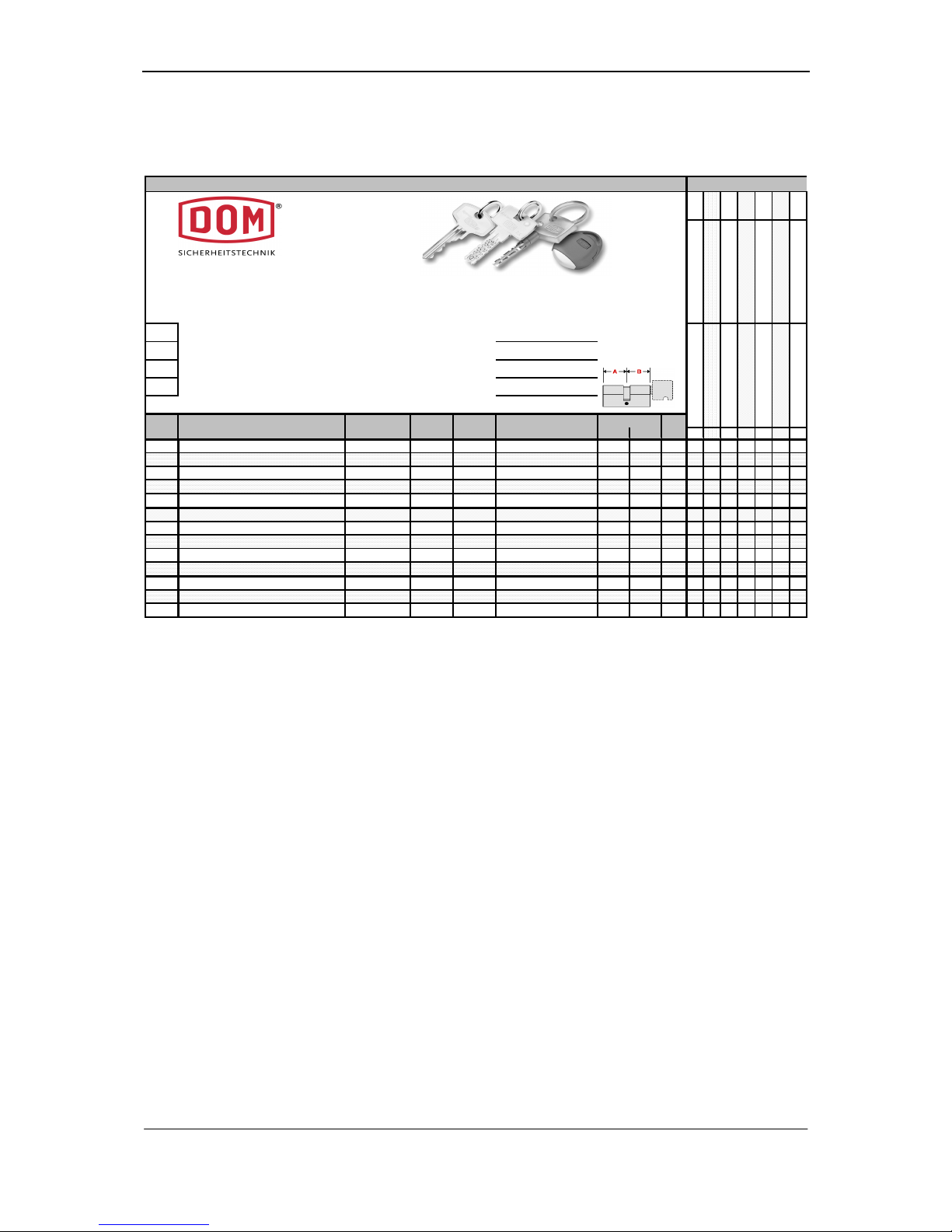
Sigma Plus
Worksheet
47
Worksheet
Pro ject: Date: 15 .07 .02
Anzahl
Worksheet
ce ntr al loc kin g sys tem s
clie nt :
ma st er key sy ste m s
com m iss ion :
ce ntr al ma ste r k ey syste ms
key sy ste m:
ce ntr al loc kin g sys tem s
sys tem :
A B
1
2
3
4
5
6
7
8
9
10
11
12
13
X = Gruppen schließt, I schließt Z bzw M, G = Gleichschließung
Pos.
Fb.TypeKe y
qua nti ty
Cyl.
Qua ntity
Ke y Nu mb er.Doo r-or ro om de script ion Len gth
All relevant information to this system, keys and its orders is provided in the work
sheet included.
Page 50

Branches
48
Should you have any questions that are not answered by the information contained in
these assembly instructions, please contact one of the branch offices in your country
directly.
Published by
DOM Sicherheitstechnik GmbH & Co. KG, 50301 Brühl
This documentation may not be reproduced, stored, transmitted or translated in any
form or via any medium, in whole or in part, without the prior permission in writing of
DOM Sicherheitstechnik GmbH & Co. KG.
Important information
This documentation is updated at regular intervals. The publisher will always be
grateful for the communication of possible errors or suggestions for this documentation.
© DOM Sicherheitstechnik GmbH & Co. KG, 50301 Brühl
 Loading...