

Page 1

Dolphin DXS410 Switch
Quick Start Guide
Revision Information: Revision 1.0
Dolphin Interconnect Solutions, 225 Cedar Hill Street, Marlborough, MA 01752
www.dolphinics.com
Page 2

April 2008
Dolphin Interconnect Solutions believes the information in this publication is correct; however, the information
is subject to change without notice.
Dolphin Interconnect Solutions does not claim that the use of its products in the manner described in this publication will not infringe on any existing or future patent rights, nor do the descriptions contained in this publication imply the granting of licenses to make, use, or sell equipment or software in accordance with the description.
If the equipment outlined in this document is used in a manner not specified by Dolphin, the protection provided
by the equipment may be impaired.
©Dolphin Interconnect Solutions. 2008. All rights reserved. Printed in U.S.A.
Page 3

Overview
Preface
This manual describes how to configure and install the DXS410 Switch.
If additional information is required, send email to Dolphin at pci-support@dolphin-
ics.com.
Refer to the DXS410 Switch Release Notes for any release specific updates.The release
notes can be downloaded from our customer support section of www.dolphinics.com.
Comments about (and corrections to) this manual can also be sent to pci-support@dol-
phinics.com.
This manual contains the following chapters and an appendix:
Chapter 1 Installation
Preface iii
Page 4
This chapter describes how to initially setup the DXS410 Switch.
1.1 Kit Contents
• DXS410 Switch
• One US Standard 3-Prong AC Power Cord
• Handling Instruction Document
1.2 Minimum Hardware Requirements
• Two DXH510 PCI Express Host Adapter
• High speed data cables
1.2.1 Cable Requirements
1
Installation
A high speed data cable is required to connect the DXS410. Dolphin provides the following cables to support the DX products (See Table 1–1).
Table 1–1 Dolphin Cable Offering
Part Number Description
DXC1M-A 1 Meter copper cable
DXC3M-A 3 Meter copper cable
FCDX10M-A 10 Meter fiber optic cable
FCDX50M-A 50 Meter fiber optic cable
FCDX100M-A 100 Meter fiber optic cable
April 2008 Installation 1
Page 5
1.3 Software Required
The DXS410 DX Switch can be used in a number of applications. Dolphin provides
specific application software to support these various applications. This software is necessary to use the DXS410. Application software can be downloaded from the Dolphin
website at http://www .dolphinics.com/support/. Software install ation instruction can be
found on the Dolphin website.
1.4 Hardware Installation Procedure
1. Remove the chassis from the box
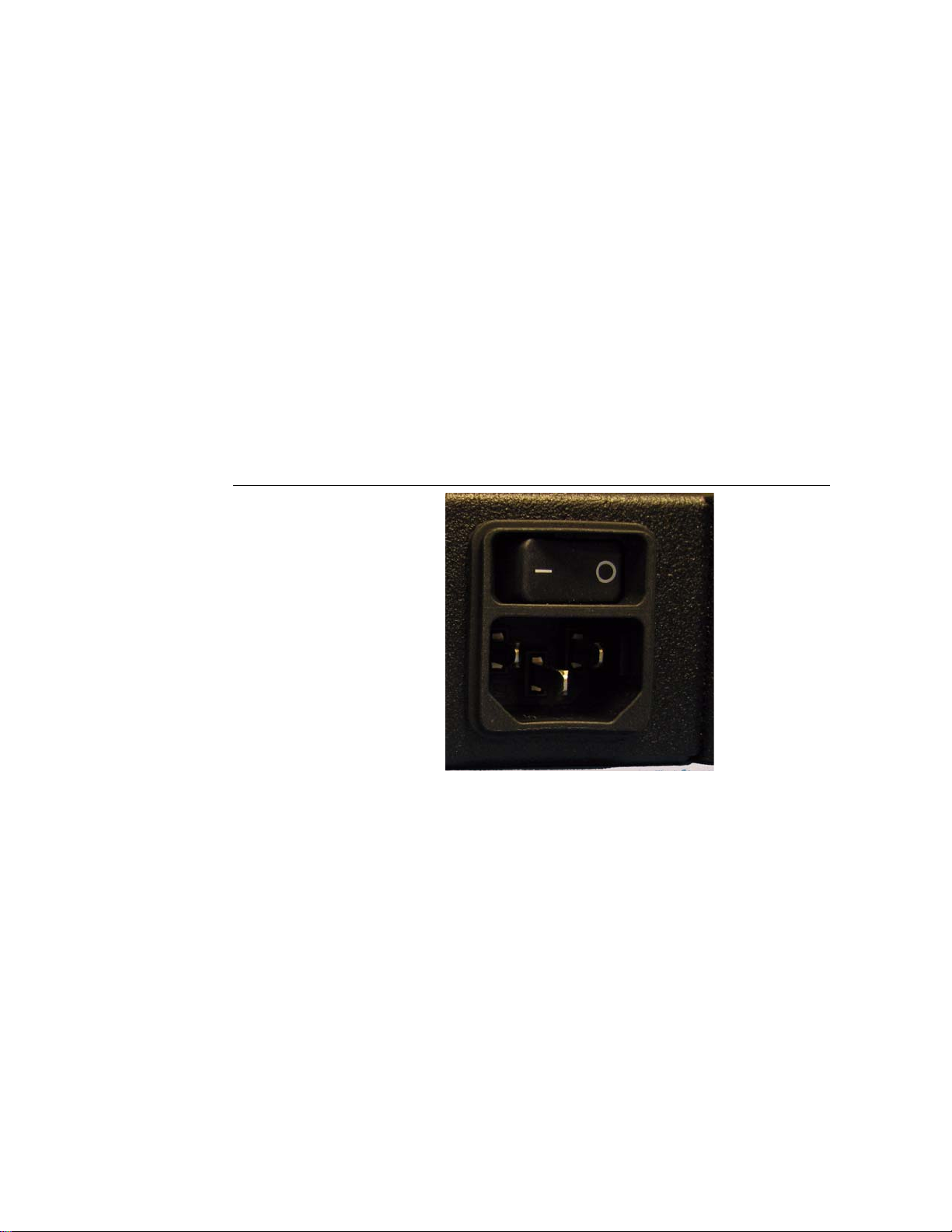
2. Connect main power (100-240VAC) using the provided AC power cord or a region ally appropriate AC power cord to the DXS410 power connector, which is located
on the front of the chassis see Figure 1–1. The power supply will accept any voltage
from 100V to 240VAC at frequency of 50-60Hz.
Figure 1–1 AC Power Inlet
3. Turn on the AC power switch on the front of the DXS410. This will apply AC
power to the chassis.
4. The DXS410 switch will go through a self test. You will observe that for 0.5 seconds the 10 Port LEDs turn green and that the red alarm LED along with the green
power LED turn on. Then for 0.5 seconds, the 10 Port LEDs turn yellow while the
other 2 LEDs stay on. The 10 Port LEDs and the Alarm LED will then turn off
while the power LED is kept on.
5. Insert one or more cables into the connectors on the front of the switch box. The
connectors are labeled for x4 or x8 operation as show in Figure 1–2.
April 2008 Installation 2
Page 6
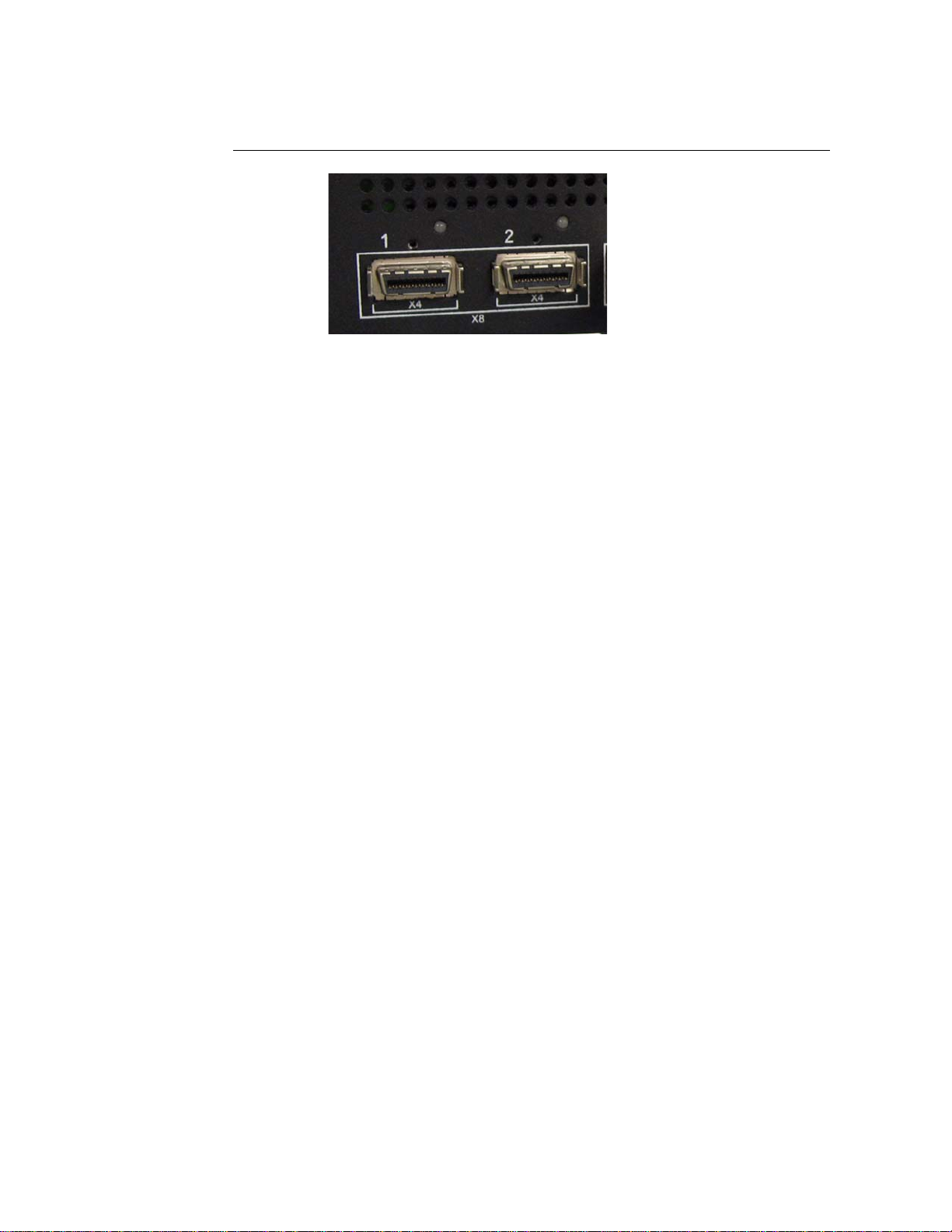
Figure 1–2 Front Panel connectors
Connecting cables
Note:
For x4 operation connect a cable to one or mor e of the ten DXS410 fr ont ports. Connect
the other end of the cable to each targeted device, such as a DXH510 host adapter
board. A single cable is required to connect to each device you intend to connect at x4
speeds. For examples, you can connect port 1 on the switch box to port 0 on a DXH510
HBA board.
For x8 operation two cables are necessary to form a x8 connection. When connecting
ports make sure you ar e connecting lower ports to lower ports and upper ports to upper
ports. The lower ports of the DXS410 ar e ports 1,3 ,5,7 and 9. T he upper ports are ports
2,4,6,8 and 10. The silk screen outlines the connection ports for a x8 connection. For
example to create a x8 connection to a host, connect ports 1 and 2 on the switch box to
the corresponding ports 0 and 1 on a DXH510 HBA, with port 1 on the switch connected to port 0 on the HBA and port 2 on the switch connected to port 1 on the HBA.
6. For clustering applications, install at least one DXH510 HBAs in two or more host
PCs using a PCIe slot that support x8 or x16 peripheral cards. Follow PC manufacturer’s instructions for installing peripheral cards.
7. Install the appropriate application software depending on your application. See
software installation guide on Dolphin’s website
8. Connect the cable or cables as outlined above.
9. Follow the instruction in the software installation guide for configuring the system.
When the configuration is completed. The LEDs on the DXS410 should tu rn a solid
green as shown in Figure 1–3. In the case of a x4 connection, each LED will be lit
April 2008 Installation 3
Page 7
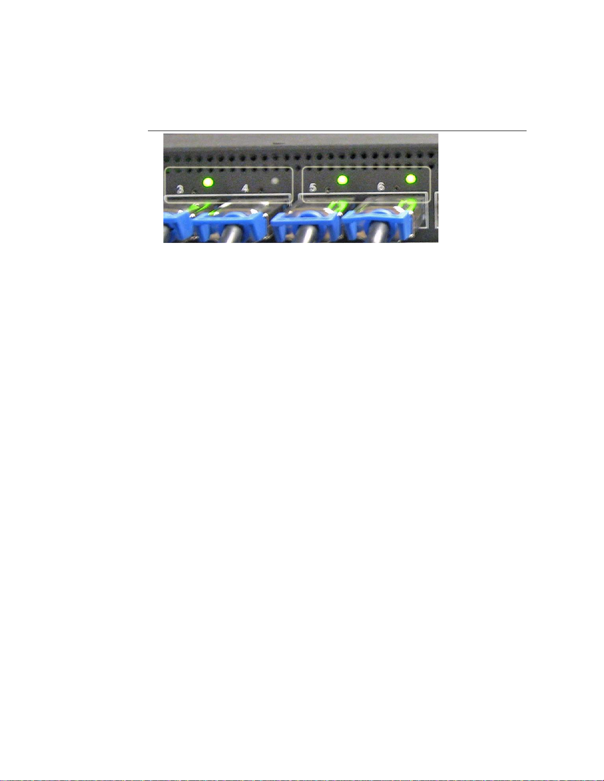
for the associated link. For a x8 connection, only one LED will be lit over the lower
port.
Figure 1–3 Switch LEDs
Ports 3 and 4 illustrate a x8 connection with a single LED lit while Ports 5 and 6 illus-
Note:
trate two independent x4 connections with a LED lit for each port.
10. The switch is now ready to use
April 2008 Installation 4
 Loading...