

Page 1

Dolby Vision CMU
User Manual
Version 3.0
November 1, 2018
Confidential information
Page 2

Confidential Information
Copyright
©
2018 Dolby Laboratories. All rights reserved. For information,
contact:
Dolby Laboratories, Inc.
1275 Market Street
San Francisco, CA 94103-4810
Telephone 415-558-0200
Fax 415-863-1373
http://www.dolby.com
Confidential information
Confidential information for Dolby Laboratories Licensees only. Unauthorized use, sale, or duplication is
prohibited.
Confidential information for OEM customers of Dolby Laboratories only. Unauthorized use, sale, or duplication
is prohibited.
Patents
This product is protected by one or more patents in the United States and elsewhere. For more
information, including a specific list of patents protecting this product, please visit
http://www.dolby.com/patents.
Trademarks
Dolby and the double-D symbol are registered trademarks of Dolby Laboratories. Following are trademarks of
Dolby Laboratories:
®
Dolby
Dolby Atmos
Dolby Audio
Dolby Cinema
Dolby Theatre
Dolby® Vision
Dolby Voice
Feel Every Dimension in Dolby
Feel Every Dimension
Feel Every Dimension in Dolby Atmos
Dolby Digital Plus
Dolby Advanced Audio
Dolby Home Theater
Dialogue Intelligence
Dolby Digital Plus Home Theater
MLP Lossless
Pro Logic® Surround EX
Dolby Digital Plus Advanced Audio
All other trademarks remain the property of their respective owners.
®
™
™
®
™
®
™
™
™
®
™
™
™
™
™
™
™
Dolby Vision CMU user manual Page 2
Page 3

Confidential Information
Table of Contents
1 INTRODUCTION ................................................................................................................................. 5
2 SETUP .................................................................................................................................................... 6
INITIAL CONNECTIVITY ................................................................................................................... 6
NETWORK SETUP ............................................................................................................................. 7
DHCP network configuration .................................................................................................. 7
Static DHCP network configuration ........................................................................................ 7
Static IP address configuration ............................................................................................... 8
Network verification ................................................................................................................. 8
SINGLE CARD AJA KONA 4 SETUP FOR 2K/HD .............................................................................. 8
Single-link 3G Level A/B Setup ................................................................................................ 9
Dual-link 1.5G HDSDI Setup .................................................................................................. 9
SINGLE CARD AJA CORVID 88 SDI SETUP FOR 2K/HD/4K/UHD ................................................ 10
Single-link 3G Level A/B Setup .............................................................................................. 10
Dual-link 1.5G HDSDI Setup ................................................................................................ 10
Quad-link 1.5G/3G Level A/B Setup ...................................................................................... 10
DUAL CARD AJA KONA 4 SETUP FOR HD/2K/UHD/4K ............................................................... 11
Single-link 3G Level A/B Setup .............................................................................................. 12
Dual-link 1.5G HDSDI Setup ................................................................................................ 13
Quad-link SDI Level A/B Setup .............................................................................................. 13
Quad-link HD Split-Quadrant Configuration for Dual Kona 4 ............................................ 14
SIGNAL VERIFICATION ................................................................................................................... 14
3 LICENSE ACTIVATION .................................................................................................................. 15
LICENSING STATUS ........................................................................................................................ 15
OBTAINING THE CMU HOSTID ..................................................................................................... 16
INSTALLING THE CMU LICENSE .................................................................................................... 17
4 CMU OPERATION ............................................................................................................................ 18
CMU HOME PAGE ......................................................................................................................... 18
CMU CONFIGURATION PAGE ........................................................................................................ 20
CMU LOG PAGE ............................................................................................................................ 22
CMU USER MANUAL ..................................................................................................................... 22
5 TROUBLESHOOTING ..................................................................................................................... 23
ERROR MESSAGES THAT CAN BE DISPLAYED ON THE CMU HOME PAGE ..................................... 23
WEB BROWSER SUPPORT ............................................................................................................... 23
Enabling JavaScript in Safari ................................................................................................ 24
Enabling JavaScript in Chrome ............................................................................................. 24
6 SPECIFICATIONS ............................................................................................................................. 25
7 FORMAT AND SIGNAL COMPATIBILITY ................................................................................. 26
Dolby Vision CMU user manual Page 3
Page 4

Confidential Information
Table of figures
Figure 1: Dolby Vision CMU workflow diagram ......................................................................................... 5
Figure 2: Dolby Vision CMU front panel ...................................................................................................... 6
Figure 3: Dolby Vision CMU rear panel ....................................................................................................... 6
Figure 4: Single AJA Kona 4 interfaces ........................................................................................................ 8
Figure 5: AJA Corvid 88 SDI interfaces ..................................................................................................... 10
Figure 6 Corvid 88 SDI HD Split-Quadrant window configuration ........................................................... 11
Figure 7: Dual AJA Kona 4 interfaces ......................................................................................................... 12
Figure 8 CMU Home page, no license ........................................................................................................ 15
Figure 9 CMU License page - no license .................................................................................................... 16
Figure 10 CMU License page - valid license .............................................................................................. 17
Figure 11: CMU Home page ....................................................................................................................... 18
Figure 12: CMU Configuration page ........................................................................................................... 20
Figure 13: CMU Log page ........................................................................................................................... 22
Figure 14: CMU User manual ..................................................................................................................... 22
Dolby Vision CMU user manual Page 4
Page 5
Confidential Information
1 Introduction
The Dolby Vision Content Mapping Unit (CMU) is an external processing box provided by Dolby that
enables the following Dolby Vision functionality:
• Enables the GUI and controls for Dolby Vision in a Dolby Vision-enabled color grading or
mastering system
• Contains the master database for Dolby Vision Mastering Monitors and output Target displays
• Real-time Content Mapping (CM) processing
The CMU performs the content mapping function from content with embedded Dolby Vision metadata
through a SDI interface for a selected target display. The applications enabled with Dolby Vision must
also communicate with the CMU via a network; either connected directly or as part of a larger house
network. This traffic is minimal and generally only occurs at startup or project initialization time. The
following CMU setup procedure shows how to setup and test the network and briefly describes SDI
connectivity.
Alternatively, you can send content with embedded Dolby Vision metadata through HDMI tunneling for
quality control.
Note:
• HDMI tunneling with a consumer TV should not be used for mastering.
• HDMI tunneling output only supports HD resolution. This signal will be upscaled in the TV.
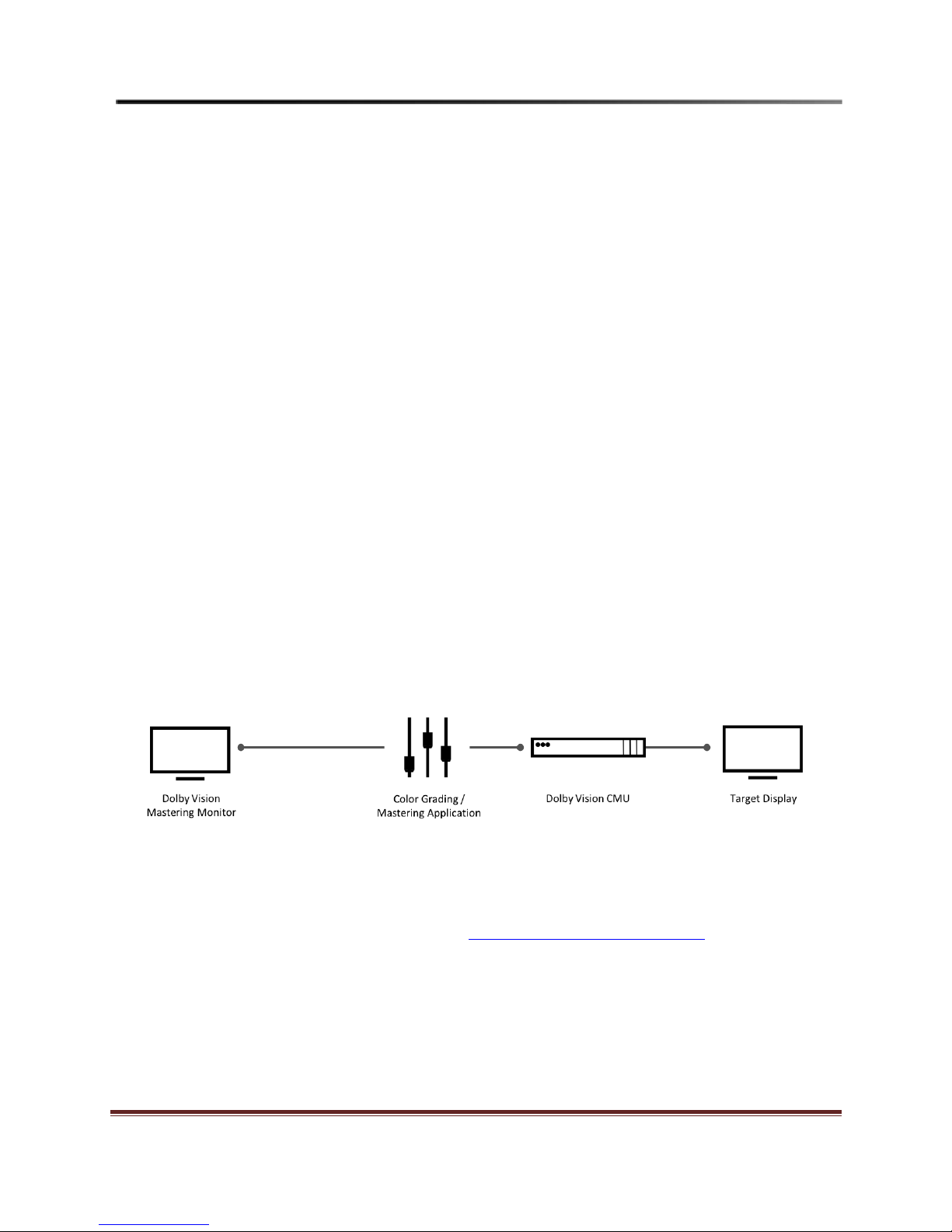
The following diagram shows the most common configuration for the CMU in an operating environment.
Figure 1: Dolby Vision CMU workflow diagram
For support and questions, send a detailed email to: dolbyvisionmastering@dolby.com
Dolby Vision CMU user manual Page 5
Page 6

Confidential Information
2 Setup
Initial connectivity
The CMU is a head-less box designed to reside in a rack in the server room with no GUI explicitly
running. This is only an issue when the network has not been configured to work for the environment in
which it is installed. Therefore, it is advisable to setup the machine with a VGA monitor and USB
keyboard before you begin operations.
Follow these steps to connect to the network.
1. Unbox the CMU and connect power, making sure there is sufficient ventilation top and bottom.
2. For SDI connection, locate the included mini-SDI-to-SDI cable harness that connects the CMU to
the color grading or mastering system.
3. For connecting a display to the CMU, either use the included mini-SDI-to-SDI cable harness to
connect to a reference monitor or the included mini-HDMI cable to a Dolby Vision TV.
4. Connect a network cable to the first port (nearest the USB ports) and plug it into the switch or
other networking infrastructure in which the color grading or mastering system is also connected
to.
5. Plug a USB keyboard into a USB slot. You do not need a mouse, as there is no graphical user
interface.
6. Connect a monitor to the VGA port. Do not connect the monitor to the graphics card.
7. Plug in the power cable and turn on the machine; all the services will automatically start.
The following figures show the front and back of the Dolby Vision CMU.
Figure 2: Dolby Vision CMU front panel
Dolby Vision CMU user manual Page 6
Figure 3: Dolby Vision CMU rear panel
Page 7

Confidential Information
Network setup
Configure the default network for DHCP. If the installation site has a DHCP server, it automatically
negotiates an address. However, many networks either use static DHCP, or manually assigned addresses.
In these environments, it is necessary to assign a static IP address.
Once you have determined the type of network to use, log in to the CMU using the following user name
and password:
User name: admin
Password: Dolby1234!
DHCP network configuration
For a DHCP network, make sure that the CMU has connected and successfully obtained an IP address. To
obtain the IP address, run the following command once logged in:
/sbin/ifconfig
Example Output:
[admin@dlb-cmu-06 ~]$ ifconfig
enp5s0f0: flags=4163<UP,BROADCAST,RUNNING,MULTICAST> mtu 1500
inet 10.204.189.27 netmask 255.255.192.0 broadcast 10.204.191.255
inet6 fe80::ec4:7aff:fe02:8196 prefixlen 64 scopeid 0x20<link>
ether 0c:c4:7a:02:81:96 txqueuelen 1000 (Ethernet)
RX packets 606 bytes 60305 (58.8 KiB)
RX errors 0 dropped 0 overruns 0 frame 0
TX packets 126 bytes 20113 (19.6 KiB)
TX errors 0 dropped 0 overruns 0 carrier 0 collisions 0
device memory 0xfb220000-fb240000
Note: It may take 30 to 60 seconds to bind to a DHCP server if the DHCP servers have churn processing
turned on.
Static DHCP network configuration
For a static DHCP network in which the network addresses are served based on the MAC address, log in
and run the following command to display the CMU’s MAC address:
/sbin/ifconfig
There may be multiple network devices on the CMU. Depending on the physical setup, the MAC address
you want should be attached to network device enp5s0f0 or en0 depending on the CMU’s generation.
Provide this MAC address the networking administrator. Once the MAC address is entered to their
Dolby Vision CMU user manual Page 7
Page 8
Confidential Information
system, simply reboot, and make sure the network automatically picked up as occurs in a normal DHCP
network.
Static IP address configuration
The most complicated setup configuring for a static IP address. Contact your Linux administrator to setup
the CMU for a static IP configuration.
Network verification
After configuring the network settings on the CMU, access the built-in web application by opening a web
browser on Chrome, Firefox or Safari on a computer that is connected to the same network.
Navigate to the CMU IP address you assigned for the CMU to display the CMU web page. For future
access, create a bookmark. It is useful to check the SDI status and other log pages during operation.
Single Card AJA Kona 4 setup for 2K/HD
The CMU with a single AJA Kona 4 SDI card is compatible with a dual-link 1.5G HDSDI, single-link 3G
Level A/B SDI or quad-link 3G Level A/B SDI, depending on the hardware configuration of the CMU.
The CMU automatically configures the output SDI interface to match the input SDI interface. If needed,
the CMU can be set to force a 3G SDI output, even if the input SDI is dual-link HDSDI, see the CMU
Configuration page.
Additionally, the CMU with Kona 4 supports HDMI output to a Dolby Vision television.We
recommend that you use 3G connectivity, because of the reduced wiring necessary. Additionally, there
are fewer timing and VPID identification issues when using 3G connectivity. The CMU is designed to
process 12-bit RGB 4:4:4 content; therefore, the supported frame rates are only those in which a 4:4:4
RGB signal can be displayed (23.976, 24, 25, 29.976, 30 are all possible). The CMU examines the input
signal and adapts based on the VPID and connection state it detects on the wire. If the application does
not output a VPID, it assumes 24fps 4:4:4 RGB 12-bit.
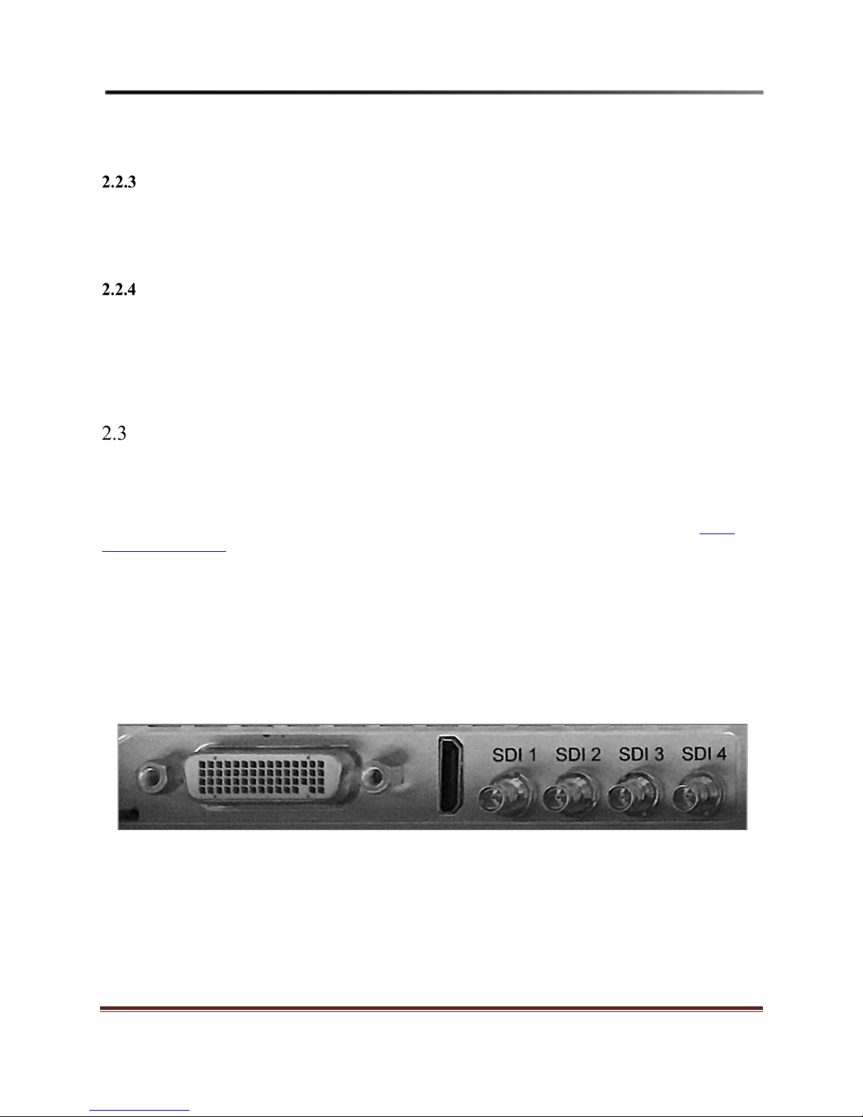
Figure 4: Single AJA Kona 4 interfaces
Dolby Vision CMU user manual Page 8
Page 9

Confidential Information
Single-link 3G Level A/B Setup
2.3.1.1 SDI output
Use the following SDI configuration to connect using single-link 3G SDI. See Figure 4 for SDI connector
configuration.
SDI 1 = input from application
SDI 3 = output to target monitor
SDI 2, 4 = not used
2.3.1.2 HDMI output
Use the following HDMI configuration to connect using single-link 3G SDI. See Figure 4 for SDI
connector configuration.
HDMI = output to Dolby Vision television
SDI 1 = input from application
SDI 2, 3,4 = not used
Dual-link 1.5G HDSDI Setup
2.3.2.1 SDI output
Use the following SDI configuration to connect using dual-link 1.5G HDSDI. See Figure 4 for the SDI
connector configuration.
SDI 1 = A side of dual-link input from application
SDI 2 = B side of dual-link input from application
SDI 3 = A side of dual-link output to target monitor
SDI 4 = B side of dual-link output to target monitor
2.3.2.2 HDMI output
Use the following HDMI configuration to connect using dual-link 1.5G HDSDI. See Figure 4 for the SDI
connector configuration.
HDMI = output to Dolby Vision television
SDI 1 = A side of dual-link input from application
SDI 2 = B side of dual-link input from application
SDI 3, 4 = not used
Dolby Vision CMU user manual Page 9
Page 10

Confidential Information
Single Card AJA Corvid 88 SDI setup for 2K/HD/4K/UHD
The CMU with a single AJA Corvid 88 SDI card is compatible with dual-link 1.5G HDSDI, single-link
3G Level A/B and quad-link 3G Level A/B.
Figure 5: AJA Corvid 88 SDI interfaces
NOTE: The Corvid 88 does not support HDMI tunneling as there is no HDMI interface using this card.
Single-link 3G Level A/B Setup
Use the following SDI configuration to connect using single-link 3G SDI. See Figure 5 for SDI connector
configuration.
SDI 1 = input from application
SDI 5 = output to target monitor
SDI 2, 3, 4, 6, 7, 8 = not used
Dual-link 1.5G HDSDI Setup
Use the following SDI configuration to connect using dual-link 1.5G HDSDI. See Figure 5 for SDI
connector configuration.
SDI 1 = A side of dual-link input from application
SDI 2 = B side of dual-link input from application
SDI 5 = A side of dual-link output to target monitor
SDI 6 = B side of dual-link output to target monitor
SDI 3, 4, 7, 8 = not used
Quad-link 1.5G/3G Level A/B Setup
Use the following SDI configuration to connect using single-link 3G SDI. See Figure 5 for SDI connector
configuration.
SDI 1, 2, 3, 4 = input from application
SDI 5, 6, 7, 8 = output to target monitor
Dolby Vision CMU user manual Page 10
Page 11

Confidential Information
2.4.3.1 Quad-link HD Split-Quadrant Configuration for Corvid 88
The following diagram shows the SDI HD Split-Quadrant window configuration for the Corvid 88.
Figure 6 Corvid 88 SDI HD Split-Quadrant window configuration
Dual Card AJA Kona 4 setup for HD/2K/UHD/4K
The CMU with dual AJA Kona 4 SDI cards is compatible with dual-link 1.5G HDSDI, single-link 3G
Level A/B and quad-link 3G Level A/B. The cards are configured individually as primary and secondary.
The Primary AJA Kona 4 card is always the input and the Secondary AJA Kona 4 card is always the
output.
Usually, the bottom card is the Primary SDI card (input) and the top card is the Secondary SDI card
(output) but this is not always the case. If the source device cannot communicate with the CMU or there is
no video output, try switching between cards.
Additionally, the CMU with Kona 4 supports HDMI output to a Dolby Vision television.
The following sections describes the various SDI configurations.
Dolby Vision CMU user manual Page 11
Page 12

Confidential Information
Figure 7: Dual AJA Kona 4 interfaces
Single-link 3G Level A/B Setup
2.5.1.1 SDI
Use the following SDI configuration to connect using single-link 3G SDI. See Figure 7 for connector
configuration.
Primary Card SDI 1 = input from application
Primary Card SDI 2, 3, 4 = not used
Secondary Card SDI 1 = output to target monitor
Secondary Card SDI 2, 3, 4 = not used
2.5.1.2 HDMI
Use the following HDMI configuration to connect using single-link 3G SDI. See Figure 7 for connector
configuration.
Primary Card SDI 1 = input from application
Primary Card SDI 2, 3, 4 = not used
Secondary HDMI = output to Dolby Vision television
Secondary Card SDI 1, 2, 3, 4 = not used
Dolby Vision CMU user manual Page 12
Page 13

Confidential Information
Dual-link 1.5G HDSDI Setup
2.5.2.1 SDI
Use the following SDI configuration to connect using dual-link 1.5G HDSDI. See Figure 7 for connector
configuration.
Primary Card SDI 1 = A side of dual-link input from application
Primary Card SDI 2 = B side of dual-link input from application
Secondary Card SDI 1 = A side of dual-link output to target monitor
Secondary Card SDI 2 = B side of dual-link output to target monitor
Primary Card SDI 3, 4 = not used
Secondary Card SDI 3, 4 = not used
2.5.2.2 HDMI
Use the following HDMI configuration to connect using dual-link 1.5G HDSDI. See Figure 7 for
connector configuration.
Primary Card SDI 1 = A side of dual-link input from application
Primary Card SDI 2 = B side of dual-link input from application
Primary Card SDI 3, 4 = not used
Secondary Card HDMI = output to Dolby Vision television
Secondary Card SDI 1, 2, 3, 4 = not used
Quad-link SDI Level A/B Setup
2.5.3.1 SDI
Use the following SDI configuration to connect using quad-link SDI. See Figure 5 for connector
configuration.
Primary Card SDI 1, 2, 3, 4 = input from application
Secondary Card SDI 5, 6, 7, 8 = output to target monitor
2.5.3.2 HDMI
Use the following HDMI configuration to connect using quad-link SDI. See Figure 5 for connector
configuration.
NOTE: HDMI tunneling output will be HD resolution. This signal will be upscaled in the TV.
Primary Card SDI 1, 2, 3, 4 = input from application
Secondary Card HDMI = output to a Dolby Vision television
Secondary Card SDI 5, 6, 7, 8 = not used
Dolby Vision CMU user manual Page 13
Page 14

Confidential Information
Quad-link HD Split-Quadrant Configuration for Dual Kona 4
The following diagram shows the SDI HD Split-Quadrant window configuration for dual Kona 4s.
Signal verification
Once the application is running and providing a signal to the CMU with the embedded Dolby Vision
metadata, connect to the CMU’s web page, and check the status information. If everything is working
correctly, the host application populates the user interface menus with available displays for targeting, and
the status is Processing Normally. If another status appears, it may mean further debugging is necessary.
See Troubleshooting for further information.
Dolby Vision CMU user manual Page 14
Page 15

Confidential Information
3 License activation
The CMU requires a valid license to function and enable certain Dolby Vision features that are supported
on partner tools that support Dolby Vision workflows. Without a valid license, the CMU does not
communicate to a connected third party tool, and will not perform the Content Mapping functions.
To activate the CMU, you must install a valid license. Contact your sales or support person at Dolby
Laboratories to submit the CMU’s required HostID and to receive a valid license to activate the CMU.
Once you receive a valid license, install it on the CMU. The license is only valid for a single CMU, and
cannot be transferred to other CMU machines. If there are multiple CMUs in the facility, each CMU
requires a unique license.
Follow the steps in the following sections for license activation.
Licensing status
When the CMU license is not installed, or has expired, the CMU stops processing and displays the video
with the No license message. The CMU home screen displays the following message:
Process State: No Dolby Vision CMU License
Figure 8 CMU Home page, no license
Dolby Vision CMU user manual Page 15
Page 16

Confidential Information
Obtaining the CMU HostID
On the Licensing tab of the CMU, copy the HostID information, send it to Dolby along with your
company and contact information to receive a license.
Figure 9 CMU License page - no license
Dolby Vision CMU user manual Page 16
Page 17

Confidential Information
Installing the CMU license
To install the license file, select Upload License File and install the license.bin file you received
from Dolby. Once the license file is installed, the CMU is active and the web page displays the license
expiration date.
Figure 10 CMU License page - valid license
Dolby Vision CMU user manual Page 17
Page 18

Confidential Information
4 CMU Operation
The CMU has a web page user interface that can be accessed using most web browsers that are connected
on the same network. See Web browser support for supported browsers. In a web browser enter or
navigate to the CMU web application IP address. The CMU web application provides valuable
information, such as Operation Status, Configuration Status and troubleshooting logs.
CMU Home page
The Home Page displays the operational status of the CMU and provides some basic controls.
Dolby Vision CMU user manual Page 18
Figure 11: CMU Home page
Page 19

Confidential Information
Parameter
Description
Process State
Appears if the application and CMU are communicating, and
if and metadata is transported through SDI.
Active Profile
Displays the selected active profile. The active profile
renders to the target display.
Input
Displays the video input format sent by the application.
Output
Displays the video output format sent out by the CMU.
Parameter
Description
Normal
The normal CMU operating mode.
Pass-Thru
Enables the signal from the application to pass through the
CMU to the connected target display without Content
Mapping processing.
Black-Out
Outputs a full-screen black frame to the target display.
Bars
Forces the CMU to output a colorbar test pattern.
Ramp
Forces the CMU to output a ramp test pattern.
Restart
Restarts the SDI capture card.
Refresh
Refreshes the CMU status information.
The Home menu displays the operational status for the CMU. It also includes options to view the Process
State, Active Profile, software version, and input and output format.
When the CMU is functioning correctly, the Process State is, Processing normally and no error messages
should appear. If there is an issue, an error message appears and that can help when troubleshooting. For
more information, see Troubleshooting.
These are following controls are available for the CMU. When using the CMU to create or playback
Dolby Vision content, set the CMU to Normal mode.
Dolby Vision CMU user manual Page 19
Page 20

Confidential Information
CMU Configuration page
Use this page to configure the CMU Unique ID, Machine Name, Video Input and Output configuration.
When setting the source output for HD or UHD resolutions, the user will need to manually set the
appropriate resolution on the CMU webpage.
When setting up multiple CMUs on a network, each CMU requires a unique ID Number and Name to
avoid machine conflicts and easily identify each CMU. Use this configuration page to set the CMU’s
unique ID and Name.
Dolby Vision CMU user manual Page 20
Figure 12: CMU Configuration page
Page 21

Confidential Information
Parameter
Description
ID
Enter a new CMU Identification number.
1-4 are valid; only use when connecting to multiple
CMUs.
New Name
Enter a unique CMU machine name to identify the
CMU if there are multiple CMUs on the network.
Input
HD/2K
Configures the CMU for HD video resolutions.
UHD/4K
Configures the CMU for UHD video resolutions.
Output
SDI
Sends the image through SDI (default).
HDMI tunneling
Sends the image through HDMI to a Dolby Vision
television
L5 ON/OFF
Enables or disables sending the active area metadata
(Level 5) to the connected Dolby Vision TV.
NOTE: Disabling this function will cause the
letterboxed areas in the TV to lift when positive lift
trim is applied.
Edit the following parameters for each CMU.
NOTE: The CMU does not support simultaneous HDMI and SDI video output.
Dolby Vision CMU user manual Page 21
Page 22

Confidential Information
CMU Log page
The CMU Log page displays any CMU configuration updates, warnings, or errors. Use this page for
debugging purposes. Use the Download field to select the date range for the logs you want to download.
The default download period is one week prior from the current date.
Figure 13: CMU Log page
CMU user manual
To view the manual at any time, select the Manual tab on the top bar and it will display the PDF user
manual.
Figure 14: CMU User manual
Dolby Vision CMU user manual Page 22
Page 23

Confidential Information
5 Troubleshooting
Error messages that can be displayed on the CMU Home page
Processing Normally: The system is connected to the application and working
properly.
No Dolby Vision CMU License: The CMU license is missing or expired.
Unexpected CMU Input: The CMU is only compatible with RGB input signal
format. Confirm the application is outputting in RGB
format and not YCbCr or XYZ formats.
No metadata: The application is not sending Dolby Vision metadata
over SDI. Confirm the application and project are
configured properly to work in Dolby Vision. Also
check the SDI is routed correctly from the application to
the CMU.
The video output will also display the No metadata
error message.
Invalid L1 Metadata: The application may have corrupted Dolby Vision
metadata. Rerun Analysis on the application for the
shot.
Web browser support
The CMU web UI supports most popular web browsers, such as Chrome, Safari and Firefox. You must
enable JavaScript to ensure that the CMU web UI functions correctly.
Dolby Vision CMU user manual Page 23
Page 24

Confidential Information
Enabling JavaScript in Safari
Navigate to Preferences > Security and enable JavaScript.
Enabling JavaScript in Chrome
Navigate to Preferences > Show Advanced Settings > Privacy > Content Settings and select, Allow all
sites to run JavaScript.
Dolby Vision CMU user manual Page 24
Page 25

Confidential Information
6 Specifications
The CMU has the following specifications.
• Chassis Type - 1RU Rackmount
• Dimensions
o 17.2 inch (W) x 28.2 inch (D) x 1.7 inch (H)
o 437 mm (W) x 716 mm (D) x 43 mm (H)
• Weight
o 42 lbs / 19.1 kg
• Power
o 100VAC ~ 240VAC, 50/60Hz, 1200W Max
o 300W Nominal, 1400W Max
Dolby Vision CMU user manual Page 25
Page 26

Confidential Information
SDI interface
Compatible signal
10-bit and 12-bit RGB
Dual-link 1.5G
1920x1080
p23.98
1920x1080
p24
1920x1080
p25
1920x1080
p29.97
1920x1080
p30
Single-link 3G Level B
1920x1080
p23.98
1920x1080
p24
1920x1080
p25
1920x1080
p29.97
1920x1080
p30
Quad-link 3G
Level B
3840x2160
p23.98
3840x2160
p24
3840x2160
p25
3840x2160
p29.97
3840x2160
p30
HDMI Output
Output Signal
1920x1080
p23.98
1920x1080
p24
1920x1080
p25
1920x1080
p29.97
1920x1080
p30
7 Format and signal compatibility
Dolby Vision CMU user manual Page 26
 Loading...