

Page 1
[](I
DolbY
SR
Cat.
Spectral
User
No. 280
Information
Recording
Module
Page 2
USER
INFORMATION
FOR
SPECTRAL
RECORDING MODULE
CAT. NO. 280
Dolby
U.S.A. 100
Tel: (415) 558-0200; Telex: 34409;
U.K.
Tel: 01 720-1111; Telex: 919109;
Laboratories
Potrero
346
Clapham
Avenue,
Road,
San
Incorporated
Francisco,
Fax:
London
(415) 863-1373
SW9
Fax:
01 720-4118
CA
9AP
94103
WARRANTY
defects
01'
warranty
defective,
distributor.
inadequate
Dolby
circumstances
All
ill1986
in
implied
Laboratories'
requests
Dolby
materials
warranties
period
provided
packing
INFORMATION:
and
workmanship
and
Dolby
Defects
shall
for
repairs
Laboratories
Laboratories
the
unit
caused
for
service
obligation
Dolby
or
information
Inc.
Equipment
no
warranty
is
shipped,
by
modifications,
return,
is
restricted
Laboratories
manufactured
for
one
year
of
merchantability
will
repair
prepaid,
are
not
covered
to
the
be
liable
should
include
from
or,
at
to
misuse
repair
for
any
its
the
or
by
other
the
the
accidents,
this
or
unit
by
Dolby
date
of
purchase.
or
fitness
option,
manufacturer
warranty.
replacement
damage,
serial
for a
replace
and any
number
Laboratories
There
particular
components
directly
further
of
defective
either
direct
to
ensure
is
warranted
are
no
other
purpose.
which
or
via
an
damage
parts
and
or
consequential.
rapid
service.
against
express
During
prove
authorized
caused
S871741717493
the
to
under
be
by
no
Page 3
This
Cat.
basic
familiarity
information
No. 280
principles
spectral
of
with
Dolby
is
intended
recording
audio
A-type
to
serve
module.
recording,
noise
as
an
introductory
It
assumes
complementary
reduction
and
previous
signal
interface
user's
processing,
frames.
guide
knowledge
for
and
the
of
the
some
The
both
Cat.
Dolby
Cat.
Cat.
pin
No.
A-type
No.
No.
22
22
module
established
the
rear
of
appropriate
280
and
A-type
module
and
studio
the
frame
Important
spectral
level
module.
user
can
with
continue
procedures.
Cat.
No.
type.)
Note
recording
compatible
In
most
simply
the
recording
(A
280
must
module
with
cases,
replace
Cat.
switch
be
set
No.
using
to
is
the
the
the
280
on
the
Page 4
Dolby®
Cat.
No.
280
Spectral
Recording
Module
Co",pare
DOlbY
••
Noise
Ref Tape
Auto
DD
DoibySR
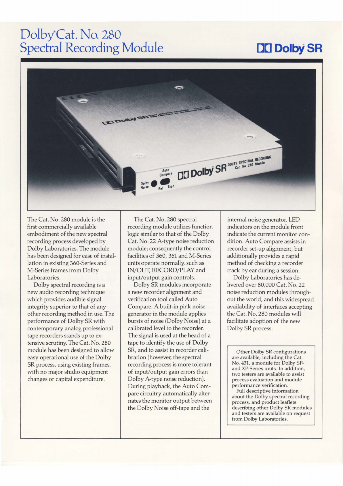
The
Cat.
No.
280 module is the
first commercially available
embodiment
recording process developed
Dolby
has been designed for ease of installation
M-Series frames from
Laboratories.
Dolby
new
audio recording technique
which provides audible signal
integrity superior to
other
recording
performance of
contemporary
tape recorders stands
tensive scrutiny.
module has been designed to allow
easy operational use of the
SR process, using existing frames,
with
no
changes
of the
new
Laboratories.
in
existing 360-Series
spectral recording
major
or
capital expenditure.
The
that
method
Dolby
analog professional
The
Cat. No. 280
studio equipment
spectral
module
Dolby
of
in use.
SR
up
to ex-
by
and
is
a
any
The
with
Dolby
The
Cat.
No.
280 spectral
recording
logic similar to
Cat. No. 22 A-type noise reduction
module; consequently the control
facilities of 360, 361
units operate normally, such as
IN/OUT, RECORD/PLAY
input
Dolby
a
new
verification tool called
Compare
generator in the module applies
bursts of noise (Dolby Noise) at a
calibrated level to the recorder.
The signal is used
tape to identify the use of
SRI
bration
recording process
of
input/output
Dolby
During playback, the
pare
nates the
the
module
/output
SR modules incorporate
recorder alignment
. A built-in
and
to assist in recorder cali-
(however, the spectral
A-type noise reduction).
circuitry automatically alter-
monitor
Dolby
Noise off-tape
utilizes function
that
of the
and
M-Series
gain controls.
Auto
pink
at
the
head
is
more tolerant
gain errors
Auto
output
between
and
Dolby
and
and
noise
Dolby
than
Com-
of a
the
internal noise generator. LED
indicators
indicate the current
dition.
recorder set-up alignment,
additionally provides a
method
track
Dolby
livered over 80,000 Cat. No. 22
noise reduction modules throughout
availability of interfaces accepting
the Cat. No. 280 modules will
facilitate
Dolby
are available, including
No.
and
two testers are available to as sist
process evaluation
performance verification.
about
process,
describing other Dolby
and
from Dolby Laboratories.
on
the module front
monitor
Auto
Compare
of checking a recorder
by
ear
during a session.
Laboratories
the
world, and
adoption
SR process.
Other
Dolby SR configurations
431
, a module for Dolby SP-
XP-Series units.
Full descriptive information
the
Dolby spectral recording
and
product
testers are available
assists in
but
rapid
has
de-
this widespread
of the
new
the
Cat.
In
addition,
and
module
leaflets
SR
modules
on
request
con-
Page 5
Dolby®
Cat.
No. 280
Specifications
INTERFACES:
The
Cat. No. 280 module can be installed
in the following frames:
Models 360 and 365
All
module
functions available, including
simultaneous
if
two
Model
and
Record
Model
Auto
361
Compare
record/play
360s are used in dedicated
Play
modes.
functional
Auto
durin
Compare
g
tape-playback following recording,
not
during
simultaneous recording.
M-Series Units
Simultaneous
The
Cat. 280 requires a special top cover
No
(Cat.
18 of M-Series interface.
CAT.
record/play
Auto
. 359) to fit in Channels 2, 10,
NO.
280 MODULE
Compare
SPEGFICATIONS:
Layout:
A
pair
of printed circuit cards
togeth
er
output
form the module. Signal
and
control functions compatible
with Cat. No. 22 noise reduction
mounted
input/
modul
Input Circuit:
680 k
ohms
unbalanced, 300 mV rms for
reference leve
l.
Peak Encode Input Level:
3.0 V rms (20
Peak
3.0 V rms from
5.0 V
Decode
rms
from
dB
above
reference level).
Output Level:
Output
1,
Output
2.
Line Amplifier:
When
mounted
output
+ 22
into 600
(0
dB = 0.775 V rms).
in interface,
dB
into bridging load, +
ohms
maximum
(A 6 dB higher level is possible using
V line-amplifier supply voltage.)
+ 36
Overall Frequency Response:
± 1 dB, 20
Hz-20
kHz
(encode/decode).
but
21
and
e.
dB
Bandwidth Limitation:
Internal filters: 10
Hz-50
kHz.
Overall Harmonic Distortion:
2nd & 3rd
below
Negligible higher
ponents
Overall
SR
105
noise level.
93
weighted noise level.
105
A- weighted noise
.
95 dB - clipping level to unweighted noise
level, 20
peak
harmonic
level, 20
each 0.3%
Hz-20
order
at
any
level.
Dynamic
System (typical}:l
dB-clipping
dB-clipping
dB
- clipping level to NAB
Hz-20
level to
level to CCIR Rec. 468-2
leve
kHz.3
distortion com-
Range
CCIR/ARM
}2
Typical Obtainable Dynamic
Range,
90-95 dB.
15
ips:
Matching Between Units:
±1
dB
at
any
level
20
Hz-20 kHz.
and any
Signal Delay:
Approximately
J.l.S
overall, encode/decode, plus delay
14
of interfaces used.
7.0
J.l.s
per channel,
Calibration Facilities:
Dolby
Noise
generator
correct levels
and
built-in meter amplifier
Output
meter.
signal
external analysis facilities.
audible
Auto
comparison
with
internally generated reference
pink
noise.
Compare
of
for establishing
frequency response, via
and
can
also be fed to
Automatic
function, allowing
Dolby
Noise from tape
Status Indicators:
Yellow LED
Dolby
Auto
status indicated
on
front of module.
(LED control signal available for remotely
situated LEDs
on
front of module indicates
Noise mode,
Compare
or
Reference/Tape function
by
red
and
lamps.)
at
3 dB
kHz.
of
frequency,
interface
green LEDs
Control Inputs:
External + 18 to +
mode
(provided in interface).
External single pole switch for process
in/out
(provided in interface).
External single pole switch for
mode
Noise
Internal three position switch to adjust
operating logic to
Model 361,
30 V to actuate record
Dolby
(provided in interface).
Models
360
or
M-Series interfaces.
and
365,
Stability:
System
is
highly stable - does
not
require
routine alignment (no adjustable internal
controls).
Operating Temperature:
Up to 45 degrees
C.
Construction:
Fiberglass printed circuits, solid state
devices
throughout;
aluminum
covers, black characters.
clear anodized
Size:
192 x 155 x
20
mm
(7.6
x 6.1 x 0.8 inches).
Weight:
500 gm
(18
oz.).
Power Requirements:
SR
circuit:
+20
V to
+28
V,
Line amplifier:
+18
V to
100-140 mA.
+36
V,
13-17 mA.
D[] Dolby
Dolby
Laboratories
San
Francisco,
Teleph
one
346
Clapham
Teleph
one
"Dolby"
and
Dolby
Laboratories
5871741717493
Specifications
CA
94103-4813,
(415)
558-0200,
Road,
(01)
720
-1111, Telex 919109.
the
double
subject
Inc.,
100
London
-D
licensing
to change
Potrero
Telex
34409.
SW9
symbo
Corporation.
without
Avenue
9Ap,
l are
,
trademarks
notice.
of
1.
Processor alon
l
evels use
2.
Weighting
pass
filter
3.
Rms
or
d.
filter
to
ensure
average
e; in interfaces,
supplemented
that
only
audible
responding
may
by
meter,
depend
25
kHz 4-pole
nois
e is
4-pole
on
line
low
measured.
filters.
-
Page 6
II
SECTION
SECTION
SECTION
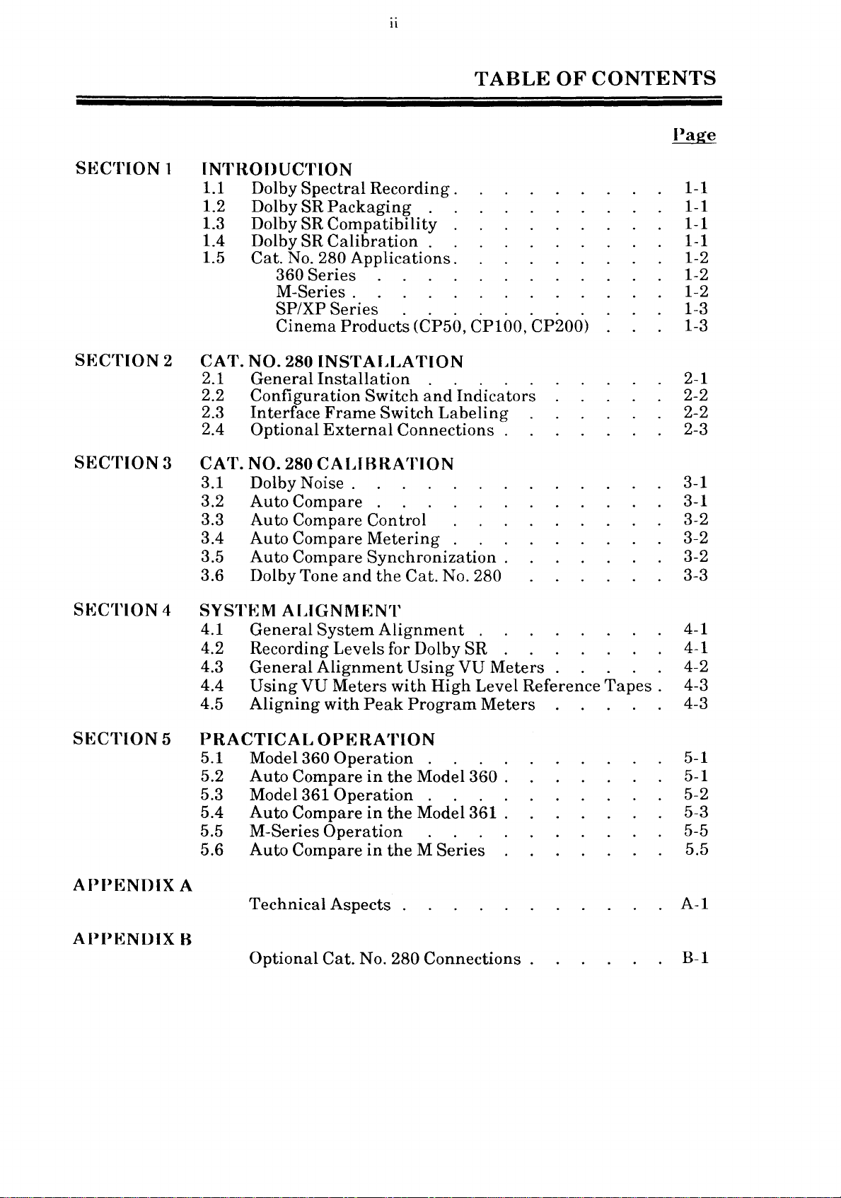
1
INTRODUCTION
1.1 Dolby
1.2 Dolby
1.3 Dolby
Spectral
SR
SR
1.4 Dolby SR
Cat.
1.5
No. 280
360
M-Series .
SP/XP
Cinema
2 CAT. NO. 280
2.1
2.2
2.3
2.4
General
Configuration
Interface
Optional
3 CAT. NO. 280
3.1 Dolby
3.2
3.3
3.4
3.5
Auto
Auto
Auto
Auto
Noise.
Compare
Compare
Compare
Compare
3.6 Dolby Tone
Recording.
Packaging
. .
Compatibility
Calibration.
Applications.
Series
Series
Products
. . . . . . . .
(CP50,
INSTALLATION
Installation
Switch
Frame
Switch
External
. . . . .
and
Connections
CALIBRATION
. 3-1
Control
Metering
Synchronization.
and
the
Cat.
TABLE
OF
CONTENTS
Page
1-1
1-1
.
.
1-1
1-1
1-2
1-2
1-2
1-3
CP100,
CP200)
1-3
2-1
Indicators
Labeling
2-2
2-2
2-3
3-1
3-2
3-2
3-2
No. 280 3-3
SECTION
SECTION
APp(i~NnIX
APP(i~NUIX
4
5
A
B
SYSTEM
4.1
ALIGNM(i:N'I'
General
System
4.2 Recording
4.3
4.4
4.5
PRACTICAL
General
Using
VU
Aligning
Alignment
OP~:RA'I'ION
5.1 Model 360
5.2
Auto
Compare
5.3 Model 361
5.4
5.5
5.6
Auto
M-Series
Auto
Compare
Compare
Technical
Optional
Alignment
Levels
Meters
with
for Dolby
with
Peak
Operation
in
the
Operation.
in
the
Operation
in
the M Series
Aspects
Cat.
No. 280
SR
Using
VU
High
Level
Program
. . . .
Model
360
. . .
Model 361 .
.
Connections.
. 4-1
4-1
Meters
Reference
Meters
Tapes.
4-2
4-3
4-3
5-1
.
5-1
5-2
5-3
5-5
5.5
A-I
B-1
Page 7
1-1
SECTION 1
INTRODUCTION
1.1
Dolby
modern
implementation
frames
widespread
1.2
To
facilitate
same
This
will
Series
unit
due
SR
module,
multi-track
While
is
one
(about
existing
cards
packaging
This
long
panel
used
in
Dolby
spectral
professional
manufactured
introduction
Dolby
easy
card
profile
allow
and
M-Series
to
incompatibilities
the
frames.
the
Cat.
major
.15
have
by
close-pitch
difference:
inch, 3 mm)
Cat.
No. 22
been
adaptation
but
thin
about 7 112
Spectral
recording,
recording.
of
this
new
by
SR
Packaging
interchange,
and
pin
the
process to be
interface
Cat.
No. 431,
No. 280
is
applications.
mounted
of
adaptation
inches,
situations.
Recording
or
Dolby SR,
recording
Dolby
ofthis
generally
the
than
the
out
as
frames.
with
will
standard
the
close
Cat.
extends
or
new
190
has
The
Laboratories
high-quality
the
the
conveniently
the
be
compatible
Cat.
To
together,
No. 280
mm,
Cat.
process.
Dolby
familiar
The
Cat.
available
Cat.
No. 22,
address
has
the
thereby
been
developed to
No. 280
It
can
recording
SR
circuit
Cat.
used
Cat.
No. 280
No.
230
for
with
No. 280
and
situations
such
Dolby
as
been
allowing
SR
module
be
used
and
the
SR
will,
format.
has
been
No. 22 noise
in
commonly
cannot
carrier
the
module
therefore
in
developed,
circuits
card.
existing
Cat.
is
where
the
Model
Dolby
answer
in
existing
therefore,
reduction
be
SP-
No. 22
physically
will
the
forward
the
is
packaged
available
used
A specific Dolby
and
XP-Series
module,
not
fit
the
Cat.
362, a special
Cat.
No. 280-L.
of
SR
modules
needs
the
first
interface
allow
in
the
module.
360-
in
the
SP
there
thicker
in
some
No. 22
the
front
to be
of
a
The
increased
in
a few
and
modules
18,
special
channels
used
1.3
Electrically,
Both
decoded
noise
or
compatible--Dolby
cards
Dolby
properly,
reduction
transmission
and
1.4
As
with
correctly
accomplished
new,
easily
DN,
is
always
thickness
module
in
these
Dolby
the
Dolby
A-type
systems
channel.
vice
versa.
Dolby
A-type
set
identifiable
noise
in
level
using
used
of
the
of
the
M-Series
covers
channels
SR
Compatibility
SR
process
NR
and
give
excellent
in
its
Dolby
SR
encoded
SR
Calibration
reduction,
with
Dolby Tone;
alignment
to
establish
Cat.
frame.
(Cat.
only.
Dolby
ability
A-type
tapes
respect
with
correct
No. 280
No. 359)
is
very
SR
are
results.
to
improve
should
Dolby
to
the
the
signal:
decode
will
not
allow
To
accommodate
must
different
complementary
Dolby
and
SR
encode
Dolby
Dolby
be
SR,
the
Dolby
not
be decoded
requires
module.
SR
Noise.
level.
process,
standard
M-series
installed
from
A-type
however,
overall
SR
are
the
Dolby
modules
channels
on
the
noise
processes
goes
quality
not
with
decode
With
it
of a recording
considered
Dolby
module
A-type,
is
achieved
Noise,
to fit
1,10
Cat.
No. 280
reduction.
that,
far
abbreviated
when
beyond
cross-
A-type
to be
this
using
is
a
Page 8
In
addition
generator,
The
Auto
gain
and
Compare
signal
verify
noise
fully
and
the
with
in
Section 3 --
to
the
the
Cat.
No. 280
Compare
frequency
mode
the
performance
the
circuit,
response
allows
internally
Dolby Noise from
Calibration.
Dolby
an
automatic
of
the
spectral
contains
using
generated
Dolby Noise
information
recording
the
1-2
recording
an
important
about
aural
pink
system
tape.
comparison
The
circuits
as a signal,
the
noise.
by
Auto
and
new
feature--Auto
gives
recording
of
the
The
user
comparing
Compare
the
Dolby
Compare.
the
user
valuable
channel.
recorded Dolby
can
quickly,
the
feature
The
by
reference
is
discussed
Noise
Auto
Noise
ear,
pink
1.5
The
following
interface
covered
Cat.
No. 280
is a summary
frames.
in
Section 5 -360
Series
Model
The
encode
two
simultaneous
Compare
record
Model 361
The
single
Cat.
playback
Auto
back
360
Model
Cat.
and
Model
No. 280
Compare
previously
Applications
A
full
Practical
360
or
decode
No.
280
feature
playback.
361
module
module
signal
of
how
discussion
Operation.
is
intended
operation.
modules
record
is
sequence
and
can
designed
for
both
is
paths
recorded
the
Cat.
of
Cat.
for
single-channel,
Two
are
required
playback
be
fully
switched
just
is
Dolby Noise.
operational
for
changeover
record
as
with
available
No. 280
No. 280
interface
for
operation.
and
playback.
into
the
the
Cat.
only
can
be
used
operation
dedicated
frames
one
channel
The
during
operation
record
No. 22.
when
playing
in
specific Dolby
in
these
and
of
Auto
both
of
a
The
and
The
units
is
Model
The
modules,
Due
modules
the
must
circuit
module,
results
length,
7t
M-Series
The
A-type
accommodate
Dolby
362
Model
to
height
cannot
Model
be
cards
with
in a module
therefore
inches
M-Series
modules.
SR
362
and
362, a special
used.
(190
in
is
designed
functions
restrictions,
be
installed.
The
that
make
one
mounted
that
extending
mm).
chassis
24
all
was
Two
or
32
channels,
to
hold
two
as a dual-channel
two
standard
To
incorporate
adaptation,
Cat.
No. 280-L
up
the
behind
is
of
single
forward
designed
chassis
channels.
provided
the
standard
thickness
of
to
can
It
that
Cat.
No. 22
Cat.
Cat.
contains
Cat.
the
other.
the
front
hold
16
be
is
possible
special
A-type
Model 360.
No. 280
Dolby
Cat.
SR
in
No. 280-L,
the
two
No. 280
This
but
double
panel
linked
by
No. 22
to
use
covers
to
Page 9
are
installed
channels
Cat.
No. 280
in
all
other
referred
Dolby
product
1, 10
to
as
on
the
and,
modules
M-series
the
distributors.
with
Cat.
No. 359, will be
Cat.
No. 280
in
the
standard
channels.
M-24
modules
unit,
covers
The
special
available
used
channel
can
be
cover,
through
in
18.
used
SP/XP
The
use
electrical
card.
SP
plug-in
combination
Cat.
Cinema
The
within
however,
CP50,
Laboratories
Series
greater
in
the
incompatibilities
The
Cat.
and
XP
replacement
No. 331 A-type
Products
Cat.
No. 280
cinema
it
CP100
thickness
SP
Series.
No. 431,
multi-track
in
existing
module
(CP50,
requires
units.
may
be
necessary
or
a CP200.
for
more
of
the
Cat.
Additionally,
with
the
due
in
late
units.
for
the
SP
in
This
entire
the
CPI00,
minor
In
a few
to
use a Cat.
In
this
information.
No. 280
Cat.
1986,
module
units
newer
prohibits
there
No. 230
will
fit
Cat.
and
XP
frames.
CP200)
modification
special
No. 280
case,
contact
its
are
some
carrier
both
the
will be a
No. 230/22
for
the
for
use
situations,
in
Dolby
a
Page 10
2-1
2.1
If
the
Cat.
No. 22 A-type module,
therefore,
interface
plugging
For
optimum
recording
and
is
installed
information
The
Cat.
Cat.
No. 22 A-type
is
important
particularly
and
below
General
Dolby
interface
simply a matter
frame,
in
the
module.
performance
system
covered
at
in
the
same
regarding
No. 280
that
the
the
chassis.
Installation
frame
setting
and
interface
Section 4.
time,
connections, etc.
module
module
adequate
M-Series
has
the
system
of
removing
the
configuration
of
the
Dolby SR circuits, however,
frame
If
the
interface
refer
to
consumes
and,
therefore,
free
air
be provided
unit,
which
CAT.
been
the
roughly
previously
is
basically
the
input
frame
appropriate
has
should
NO.
ready
existing
switch
and
output
(360
the
same
the
same
around
always
280
INSTALLATION
aligned
for use
for use.
Cat.
No. 22 from
on
the
Cat.
calibration
levels
Series
interface
or
M Series)
frame
amount
cooling
the
Dolby
requirements.
have a blank
SECTION
with
Installation
the
No. 280,
is
recommended
is
manual
of
power
interface
panel
as
frame,
2
the
is,
Dolby
and
of
the
being
for
the
It
above
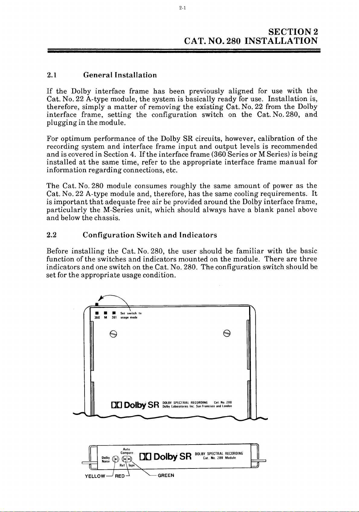
2.2
Before
function
installing
of
indicators
set
for
the
Configuration
the
Cat.
the
switches
and
one
switch
appropriate
• • • Set
360 M 361
usage
usage
n 0 II-i
U 0
O
Switch
and
No. 280,
and
indicators
on
the
Cat.
condition.
s~itCh
to
mode
SR
1.17
DOLBY
Dolby
Indicators
the
user
mounted
No. 280.
SPECTRAL
laboratories
Inc.
should
The
RECORDING
San
francIsco
be
familiar
on
the
module.
configuration
Cat.
No.
280
and
London
with
There
switch
the
basic
are
three
should
be
~~--~~~---,--~------~~--------~--------~---------~---~~-~~~-
·
SR
DOLBY
SPECTRAL
D(]
o
D
GREEN
lb
ry
Cat. No.
RECORDING
280
Module
Page 11
Cat.
No.
280
Configuration
2-2
Switch
Selects
This
usage
switch
module.
correct
operation
general,
frame
exists,
an
decode
this
"360"
Since
360,
should
If
this
may
the
The
containing
however,
M-Series
operation,
case,
position.
the
the
be
the
Cat.
switch
not
Dolby
tape
regardless
mode.
is
found
It
selects
of
it
should
be
the
when
unit)
as
the
configuration
Model
362
configuration
set
to
the
"360"
No.
280
module
incorrectly
operate
SR
will
of
correctly. No
circuits
always
the
position
(360,361, M Series)
on
the
rear
of
the
appropriate
the
Auto
set
to
Cat.
No. 280
Model 361
are
used
if
they
functions
swith
match
for
were
switch
as a dual-channel
internal
Compare
the
module.
frames
dedicated
Model
should
on
the
position.
is
set,
plugged
the
into a frame
Auto
damage
will
continue
be
properly
ofthe
to
operate
encoded
configuration
the
Cat.
circuits.
type
of
An
exception
(or
channels
encode
360
units.
be
set
Cat.
No. 280-L
Compare
will
occur,
correctly.
or
switch.
No. 280
logic for
In
interface
of
or
In
to
the
Model
with
circuit
and
decoded
Cat.
No.
YELLOW
RED
and
2.3
280
Indicators
indicator.
The
Tone/Cal
Dolby
of
Dolby
GREEN
These
audio.
noise.
played
Compare
Interface
yellow
indicator
button
Tone/CAL
Noise
Indicators.
two
LEDs
RED
ON
GREEN
off
the
is
inactive.
Frame
on
the
button
and
to
enable
indicate
indicates
ON
recorder.
Switch
is
ON
interface
is
used
the
the
the
indicates
Neither
and
whenever
frame
to
control
Auto
Reference
source
internal
the
Dolby
LED
Meter
the
is
pressed.
the
generation
Compare
(R~~n)
of
Auto
reference
Noise
is
ON
Labeling
Dolby
Dolby
The
mode.
ITape
Compare
pink
being
if
Auto
Noise
ON
(GREEN)
The
Cat.
originally
switches
installed,
the
switch
No. 280
designed
are
labeled
the
switch
labeled
card
has
for
the
inappropriately.
labeled
NR
ON/OFF
been
Cat.
Dolby
is
designed
No. 22
Tone/CAL
used
to
to be
A-type
For
is
switch
installed
NR
module;
example,
used
to
ON
or
OFF
in
with
select
the
interface
therefore,
the
Cat.
several
No. 280
Dolby Noise,
Dolby
SR
process.
frames
and
Page 12
2.4
The
main
remote
available
provided
encouraged
Auto
these
edge
display
at
that
Compare
options.
Optional
connector
of
the
the
edge
will allow
to use
more
(i:xternal
on
Auto
these
convenient.
Compare
connector
Auto
optional
Connections
the
Cat.
No. 280
status
for
other
Compare
connections
Appendix B gives
has
indicators.
uses.
circuits
Additionally, a terminal
to
terminals
The
to
be
synchronized.
make
the
specific
which
reference
use
information
can
of
pink
Dolby
be
has
The
on
used
noise
been
user
SR
using
for
is
is
and
Page 13

3-1
This
calibration.
interface
3.1
Dolby Noise
The
internal
silence.
positively
also
playback.
The
Tone"
the
section
frames
pink
signal
provide
Cat.
No. 280
or
"Cal"
front
of
noise
These
distinguish
CAT.
describes
Alignment
is covered
Dolby
is
the
the
Noise
an
alignment
is
generated
levels
periodic
synchronization
is
switched
button
Dolby
NO. 280
Dolby Noise,
and
in
Section 5 --
signal
at
an
and
then
interruptions
Dolby
on
SR
Noise
into
the
interface
module
CALIBRATION --DOLBY
Auto
operation
derived
accurate
interrupted
from
signal
will
for
the
Dolby Noise mode
frame
be
ON.
Compare
of
the
Cat.
Practical
from
internally
level
(sometimes
other
every
the
is
with
pink
Auto
pressed.
and
No. 280
Operation.
generated
respect
two seconds
called
noise.
Compare
to
These
whenever
The
SECTION
their
in
the
by
"nicks")
circuit
YELLOW
use
specific Dolby
pink
Cat.
a 20
interruptions
used
the
NOISE
during
noise.
No.
280's
ms
gap
serve
during
"Dolby
LED
3
of
to
on
When
record a
with
recording
reference
"Cal"
recorder
the
dot
Noise
will
3.2
The
verifying
reference
monitor
A/B
off
The
identification
equalization
making a recording
short
Dolby
calibration
in
read
Auto
comparison
the
Auto
tone
as
for
button
at
15 dB below Dolby Level.
the
center
on
the
Dolby
Auto
Compare
the
pink
output
tape.
Compare
section
for A-type
being
the
on
meter
calibration
recording
noise
of
settings),
Dolby
decoder.
the
interface
of
the
Level--the
Compare
feature
and
on
four-second
between
errors
using
of
Dolby Noise
recordings).
SR
When
frame
amplifier
calibration
meter
center
provides a simple
channel.
the
recorded
the
reference
feature
in
level,
azimuth,
the
Dolby
at
encoded,
Dolby
is
This
so
that
meter.
will
read
dot--when
During
Dolby
intervals.
pink
in
the
high
and
or
any
other
SR
the
beginning
This
Dolby
and
Noise
pressed),
lower
Dolby
Cat.
low
Noise
In
other
very
the
the
Auto
Noise
This
noise
No. 280
frequency
audible
process,
of
Noise
provides
is
recorded
the
Dolby Noise
level
will
words,
low
during
Dolby
provides,
Tone/Cal
and
convenient
Compare
are
alternately
generator
module
conditions.
the
user
each
reel
positively
an
accurate
(the
is
compensated
read
on
the
level
normal
button
mode,
in
effect, a
and
allows
response
(including
should
(just
identifies
"Dolby
is
sent
the
Dolby
of
playback,
way
the
switched
continuous
the
Dolby
always
as
is
done
the
alignment
Tone"
by
the
is
pressed.
of
internal
the
or
to
the
gain
in
Level
Dolby
but
quickly
to
the
Noise
easy
wrong
The
Dolby
internal
interruptions.
continuous
Noise.
is
easily
sound
properly.
Noise
reference
reference
After
identified
identical--
Two
recorded
noise,
This
several
as a tape/reference
which
LEDs
on
leads
noise
initial
they
on
the
on
the
the
other
to
an
and
four
alignment
will,
front
of
tape
hand,
easily
seconds
if
the
the
has
interruptions
is
identifiable
of
sessions,
pattern,
recorder
Cat.
No. 280
continuous
pattern
the
interrupted
the
"nicked/continuous"
even
and
Dolby
indicate
though
every
and
the
SR
whether
two seconds.
does
not
have
of
four
or
levels
seconds
"nicked"
two
noises
are
the
The
the
of
Dolby
pattern
may
aligned
monitor
Page 14

is
receiving
the
internal
recorder (GREEN).
reference
3-2
nOIse (RED)
or
the
Dolby
Noise
from
the
3.3
Auto
and
the
Auto
Compare
status
automatically
Tone/Cal
Dolby
Dolby Noise
automatically
When a Cat.
association
material.
material,
button
Tone/Cal
at
begin.
No. 280
with
If
the
the
occasionally be
reference noise
released,
The
interface
frames
of
operation
differences
exact
are
the
situation
operation
frame
used
is
are
Compare
is
controlled
of
the
begin
on
IF
the
button
its
input;
is
Dolby
Noise
button
tape
will
triggered
being
sent
returns
of
the
Cat.
for
dedicated
selected
discussed
Control
by
the
tape
the
recorder
interface
is
pressed,
the
four- second
installed,
and
is
inadvertently
not
be
by
transient
to
the
to
the
Auto
No. 280
encode/decode
by
the
in
Section 5 --
Dolby
recorder.
is
frame
the
the
Dolby
has
no
decoded
program
monitor.
normal
Compare
has
been
rear
switch
Practical
Tone/Cal
An
Auto
playing
is
pressed.
Cat.
Dolby Noise
No. 280
alternating
Tone/Cal
application
left
pressed
and
the
material,
If
the
and
the
tape
feature
installed
or
changeover
on
Operation.
button
on
the
Compare
In
other
automatically
reference/tape
button
with
other
while
Auto
Compare
resulting
Dolby
will be
Tone/Cal
correctly
depends
in
and
whether
operation.
the
module.
interface
sequence
AND
words,
sequence
is
used
tones
or
playing
circuit
in
decoded.
on
which
the
These
frame
will
the
Dolby
when
the
recognizes
will
only
in
program
program
may
bursts
button
of
is
Dolby
interface
The
mode
specific
3.4
The
calibration
designed
Level.
reading,
effects
signal
Auto
to
In
the
of
recorder
is
then
calibration
functions
normally,
An
important
Although
to
the
calibration
3.5
In
currently
circui
interface
and
XP
channels.
ts
are
Series,
frame
Auto
Regardless
remember
information.
Compare
meters
read
order
correctly
for Dolby Noise to
Dolby Noise
frequency
amplified
meter.
When
as
point
the
Dolby
established
meter
Compare
available
not
synchronized
as
suggested
the
Cat.
to
listen
Metering
in
the
on
is
band
response
so
that
the
with a Cat.
to
remember:
Noise
Dolby
whenever
Synchronization
Dolby
between
in
No.
431,
of
whether
to
only
interface
sine
waves
produce
limited
errors
Dolby
Dolby
Noise
Tone/Cal
No. 22
is
always
Level,
the
it
Dolby
interface
channels,
Appendix
Ref/Tape
synchronization
one
channel
frames
(360
at a single
an
to
reduce
at
extreme
reads
button
installed.
recorded
is
metered
Tone/Cal
frames,
unless
1.
In
the
switching
at a time
Series
level--specifically Dolby
accurate
meter
Dolby
is
at
-15
at
Dolby
button
the
Auto
the
Dolby
will
be
is
provided,
for
and M Series)
and
reliable
bounce
and
frequencies.
Level--the
not
pressed,
dB
with
Level
is
pressed.
Compare
user
has
SR
module
synchronized
it
is
valid
Auto
were
meter
reduce
The
meter
dot--on
the
meter
respect
on
the
switching
modified
for
the
between
important
Compare
the
the
the
SP
to
Page 15

3.6
Dolby
Tone
and
the
Cat.
No.
280
Dolby
application
button
Dolby
limiting
meter
gain
If
using
during
when
recorded
"Play
and
the
external
the
Tone
is
in
is
pressed
frame
and
functions
band
Dolby
playback.
Dolby
with
Cal"
on
potentiometer
Level
button
reading
is
depressed.
Note:
As a safeguard,
established
and
using
tapes
processing
interface
alignment
Tone/Cal
user
frequency
always
recording
nOise.
used
to
setting
cannot
gain
normally
establish
with
be
used.
the
decode level for Dolby SR.
the
used
When
the
Cat.
for
the
as
if a Cat.
decode level for Dolby A-type
No. 280
reading
Dolby
limiting.
interface
frame
and
the
tones, Dolby Noise will be
(Dolby Noise
Tone/Cal
the
tape
the
recorder
on
the
interface
while
the
button
recorder
Dolby Noise
will
is
pressed.)
set
(or,
frame) will
Dolby
overall
tones.
in
the
frame).
button
with
attempt
on
using
switched
is
an
response
Dolby Noise,
system
System
may
levels
conventional
off
Following
checked
using
pressed.
accurate
and
to
get
the
the
tape
to
reference
decode level,
installed,
external
Tone/Cal
No. 22
tape
recorder
correctly
read
Dolby Level
up
for a
sometimes
have
is
being
SR
levels
even
have
are
been
set
manner
(NR
OFF
that,
Dolby Noise
As
Auto
Compare
Dolby
audibly
the
is
were
installed,
set
If
tapes
different
more
to
be
played
should
though
carefully
using
with
on
the
the
Dolby
with
for
setting
the
Noise
that
match
When
the
calibration
tones
not
have
pressed,
been
for
the
on
are
played
because
proper
the
reference
conveniently,
adjusted
AND
to
the
always
the
recorder
aligned
tones
the
and
Dolby
associated
SR
level
the
Dolby
provides
playback
user
should
has
the
reference
NR
and
Dolby
meter
of
the
calibration
without
properly
decode level
calibration
that
have
flux
the
obtain
the
Dolby
be
test
SR
the
been
has
no
Tone/Cal
on
the
the
band
the
extra
aligned
meter
been
level,
the
input
Dolby
Tone/Cal
Page 16

4-1
SECTION 4
SYSTEM ALIGNMENT
4.1
This
section
SR.
As
should
(NR
OFF
4.2
Dolby Level
region,
situations.
recording
the
185 n
measured
The
Dolby
extraordinarily
1I4-inch
bench
associated
interface
most
recording
noise level
is
unwarranted.
General
covers
covered
be
set
using
on
the
Recording
can
and
the
Because
tapes,
Wblm
signal-to-noise
SR
tape.
conditions),
electronic
frame
real
recording
system
found
System
general
in
Section
external
interface
be
established
Dolby
however,
or
200 n
process
high
dynamic
In
order
the
and
the
situations
is
limited
at
the
Alignment
recording
3,
the
tones
frame).
Levels
SR
system
of
the
it
is
Wblm
ratio
is
capable
to
measure
noise
circuits
Cat.
by
recording
levels
signal
and
for
Dolby
anywhere
will
overload
recommended
region
performance.
of
range,
and
in
No. 280
with
the
location, so
levels
test
give good
characteristics
giving
in
some
such a high
overload
the
recording
module)
Dolby SR,
microphone
for
tapes
SR
in
the
that
in
order
magnetic
cases
points
such
optimum
through
with
100 n
results
signal-to-noise
must
the
the
the
Dolby
Wblm
in
associated
Dolby
to
of
system
pre-amplifiers
attention
Level be
achieve
recording
as
high
the
be
reasonably
overall
performance
Dolby
all
as
tape
(including
interface
SR
switched
through
practical
the
100
performance
to
precise
500
with
established
very
the
capacity
dB for 15
ratio
and
that
matched.
or
the
of
Dolby
frame
OFF
n
Wblm
recording
modern
highest
(under
of
the
Dolby
of
ambient
matching
in
for
IPS
test
the
In
the
The
basic
window
electronics,
and
about
tape
Wblm
n
before
of
the
n
Wblm
procedures,
Cat.
of
85 dB
has a saturation
or
the
Cat.
tape --the
as
No. 280
approximately
or
Dolby Level,
above
200 n
Note:
While
about
through
the
adjusted.
installed
level
Dolby Level.
that
output
headroom
Wblm
No.
a
reference
and
obtain
interface
is
Dolby
based
the
point
280
clips,
desired
maximum
the
clip
21 dB
the
system
in
the
+ 21
Level
level for
will
Dolby
107 dB.
is
electronic
around
is
the
and
effect.
can
point
above
frame,
For
example,
Model
dBm
into
If
the
is
be
limited
SR
The
set
to
be
chosen
the
Recording
continue
benefits
of
the
Dolby
may
be
and
how
360
600
output
equal
U.S.
system
internal
about
noise
15
dB
reference,
noise floor
SR
level,
limited
the
when
Series,
ohms --that
potentiometer
to + 8
broadcast
to 13 dB
(encode-decode)
20
dB
floor
of
above 185 n Wb/m;
measured
studios
to record
of
Dolby SR.
circuits
the
by
the
output
the
the
dBm,
applications),
above
reference
below
the
tape
that
using
themselves
actual
line
level
Cat.
maximum
is, 17 dB
has
(a
common 0 VU
the
system.
saturation
will be
use
headroom
amplifier,
has
No.
been
Dolby Level.
has
level
internal
Modern
therefore,
185 n
already
been
280
output
above
set
the
a clip-to-noise
of
the
Dolby
clip
recording
if
will
occur
essentially
Wblm
is
is
so
or
established
SR
point
185
just
that
200
Page 17

4-2
4.3
The
and
1.
2.
3.
Listed
interface
General
following
reference
Switch
interface
Play
the
Adjust
the
interface
below
frames
Alignment
is a general
tapes
the
reference
the
with
Dolby
frame).
Dolby
frame
are
with
360
Series
M
Series
alignment
a 185 n
SR
level
frame
reads
the
maximum
the
Using
Wblm
process
tape
on
"input"
the
dot
output
Cat.
No. 280
+ 20
dEm
+ 21
dEm
+ 22
dEm
+ 21
dEm
+ 22
dEm
+ 23
dEm
VU
Meters
procedure
or
200 n
Wblm
OFF
the
potentiometer
in
(NR
recorder.
the
center --Dolby Level.
levels
module
into
into
into
in
to 200
into
into
for
use
test
OFF
so
of
installed:
200
ohms
600
ohms
10 K
ohms
ohms
600
ohms
10 K
ohms
with
tape:
on
the
the
calibration
Dolby
(bridging)
(bridging)
external
associated
VU
meter
meters
Dolby
on
Adjust
4.
5.
Send a tone
the
Adjust
6.
the
7.
With
Noise.
calibration
the
"output"
interface
accomplished
Dolby
frame's
at
Dolby
Note:
The
to
region.
will
without
frequency
adjustments
switched
outside
switched
to be
the
frame
the
Dolby
Play
Dolby
have
make
consistent,
interface
record
meter.
output.
reference
with
the
sensitivity
calibration
Tone/CAL
this
section
SR
unity
If
the
the
no
the
Dolby
response
off,
700 - 1
off
for
gain
external
difference
should
potentiometer
level from
frame.
steps
circuits
SR
as
there
kHz
alignment,
and
(With
above.)
of
the
meter.
button
back
at
and
in
the
Dolby
tone
if
process
measurements
always
will
region.
turn
Dolby
to
the
the
recorder
depressed,
verify
Cat.
Level
is
in
the
alignment
switched
be
be
As
it
is
probably
SR
restore
console to
Model 361,
No.
within
this
done
noticeable
Dolby A-type
off
reference
align
to give a Dolby
record a
that
it
reads
280
have
the
frequency
is
done
in.
Tape
and
as
equalization
with
a good
well.
level
the
this
has
Level
short
Dolby
been
set
700 - 1
Dolby
deviations
kHz
band,
with
recorder
SR
must
practice
at
record
been
section
Level
it
or
be
the
Dolby
aspects
already
reading
of
Dolby
on
of
on
the
Page 18

4-3
4.4
It
has
of
250 n Wblm, 261 n
reference
have
level"
a
high
headroom
that
of
not
will
Dolby
the
suggested
either
a.
Using
become common
level for Dolby
established
and
can
flux
level
of
Cat.
the
Dolby
be
obtained.
SR
when
of
which
Establish a secondary
fixed
secondary
at
Dolby
alignment
calibration
b.
Always
reference
calibration
above Dolby Level
may
will
VU
Meters
practice
Wblm
an
alignment
be
as
high
is
set
to
No. 280
SR
processing
In
using
such a high
alignment
will
give
amount,
tone
Level--the
tone
meter.
align
tone
meter.
be
labeled
still
be
generated
with
for
or
320
SR
with
good
tone
as
1000
n
equal
will
Dolby Level
go
unused
electronics;
order
to
get
procedure.
acceptable
that
will
will
read
center
will
read
the
Dolby
to
the
The
on
the
"32"
or
and
High
many
n
Wblm,
results.
that
Wblm,
the
flux
level
The
results:
tone,
serve
lower
dot--on
interface
"DIN"
"DIN"
Dolby
not
have
metered
Level
U.S.
Reference
studios
any
of
which
Some
is closely
a few dB below
in
the
and
the
noise floor
the
full
maximum
reference
following
lower
high,
as
on
than
the
the
the
or
Dolby
recorder
interface
even
frame
dot
on
the
indication
calibration
any
upper
at
Dolby
to use a
can
European
related
tape
interface
effect
of
measured
tape,
the
it
are
two possible
reference
calibration
and
frame.
off scale,
with
upper
is
placed
meter.
mark
Level--the
Tapes
reference
be
established
studios,
to
"peak
saturation.
frame,
will
be
the
Dolby
performance
is
necessary
flux
level
however,
recording
If
such
much
of
influenced
SR
process
from
to
alter
solutions,
flux
level
tone.
console
the
part
The
on
high
of
meters
reference
the
Dolby
flux
level
the
Dolby
approximately 5 dB
(Some
at
older
all.) Dolby
center
dot.
meters
Noise
as
the
by
by
The
but
a
a
Regardless
interface
the
Dolby
Noise
The
frame,
calibration
is
pre-set
Dolby Noise
TonelCAL
Noise,
Cal"
4.5
Like
Dolby
Europe,
complex
Studios
100%
when
below
studios.
Cat.
Dolby
SR
the
on
the
VU
meters,
interface
because
program
using
reference
aligning
the
In
No. 280
SR
processing
process
Dolby TonelCAL
Aligning
100%,
established
should,
in
most
Dolby Level.
of
the
specific
Dolby Noise
to 15 dB
is
button
recorder
peak
frame.
their
material,
peak
level
Cat.
or
the
case
will
go
when
at
roughly
cases,
procedure
must
meter.
It
below
automatically
is
pressed.
button
adjusted
with
so
Peak
program
Peak
faster
rise
while
reading
and
No. 22
"peak
unused
of
the
Dolby
Dolby
and
meters,
clipping
reference"
electronics.
aligning
result
10 -
with
15
in a flux
used
be
set
is
important
the
established
restored
When
should
the
Dolby
Program
meters
can
program
times
more
VU
therefore,
or
A-type
SR,
much
the
measured
In
order
peak
dB below
level
to
set
reference
to
read
to
remember
Dolby
to
read
playing
be
pressed
calibration
Meters
be
used
meters
accurately
meters
read
need
overload
modules
alignment
of
noise
to
obtain
reading
the
peak
of
around
Dolby
Level
Dolby
back
previously
and,
meter
to
set
are
widely
indicate
the
less
point
to
set
tone,
the
available
floor
the
meters,
indications
200 n
level
through
Level--the
that
the
at
the
Level
if
when
necessary,
reads
signal
levels
used,
the
average
headroom
on
the
tape.
Dolby
Level
normally
headroom
will
be
influenced
full
benefits
Dolby
Wblm
on
Level
the
being
the
center
level
tape
of
recorder.
the
recorded
the
Dolby
level.
through
especially
peak
program
between
It
is
about
used
of
by
the
should
meters.
chosen
Dolby
dot--on
Dolby
Dolby
Dolby
"Play
the
in
level
of
level.
their
typical
5 dB
some
in
the
by
the
Dolby
be
This
for
Page 19

The
following
aligning
1.
Switch
interface
2.
Send a tone
100%)
3.
Adjust
meter
4.
Adjust
interface
5.
Send a tone
the
accomplished
Dolby
the
or
the
reads
the
Dolby
is a general
SR
using
Dolby
external
SR
frame).
from
the
if
adjusting
Dolby
the
interface
dot
in
"output"
frame.
at
reference
interface
with
the
4-4
alignment
peak
process
console
the
playback
frame
the
center --Dolby Level.
potentiometer
level from
frame.
steps
above.)
procedure
program
OFF
at
the
(With
side,
"input"
to
the
(NR
chosen
playa
restore
console to
the
Model
that
should
be followed
meters:
OFF
on
the
associated
Dolby Level (10 to 15
tape
recorded
potentiometer
unity
gain
align
361,
this
at
so
the
through
the
record
has
this
been
when
Dolby
dB
below
level.
calibration
the
Dolby
aspects
of
already
6.
7.
Adjust
the
With
Noise.
the
Dolby
the
When
Dolby Tone/CAL
calibration
Note:
Various
characteristics
aligning
reading
corresponds
indicates
optimum
which
calibration
maximum
meter.
record
frame
sensitivity
calibration
it
meter.
peak
a Dolby
meters,
to a
the
performance
corresponds
meter
program
is
replayed,
reading
and
interface
remember
numerical
studio's
should
of
meter.
button
meters
scales
standard
of
to
the
level
the
recorder
depressed,
verify
use
to
indicate
frame
that
reference
indication
the
Dolby
center
be
about
indicated
to
give
a Dolby Level
record a
that
it
reads
different
peak
with
level.
external
level
on
the
scale
operating
SR
dot
level.
circuit,
on
the
10-15 dB below
on
the
peak
short
section
Dolby
dynamic
When
peak
actually
that
For
the
level
Dolby
the
reading
reading
Level
of
Dolby
on
on
the
Page 20

5-1
There
Auto
therefore, a
appropriate
are
differences
Compare
circuit
separate
section on
in
the
detailed
between
procedure
the
following pages.
PRACTICAL
alignment
the
Model 360, Model 361
is
provided for
procedure
each.
and
Please
SECTION
OPERATION
the
operation
and
M-Series
refer
ofthe
units;
to
the
5
Page 21

5-2
5.1
Model
Two Model
and
record
playback
record (REC
button
set
The
to
the
Dolby
pressed).
"360"
connecting
allows
Dolby
The
switched
the
Tone/Cal
units
are
off (Dolby
user
alignment
installed;
playback
that
unit
calibration
restore
record
the
reference
unit
"input"
calibration
to
obtain
reference
360
Operation
360
units
and
operation
button
pressed),
The
configuration
position.
Tone/Cal
the
frames
to
buttons
with
engage
button.
initially
NR
is done
meter.
is, a
is
adjusted
The
in
the
reference
level to
is
adjusted
by
potentiometer
meter.
The
level
two
Cat.
No. 280
without
while
the
switch
on
the
a 1I4-inch
the
Dolby Noise
aligned
and
with
Dolby
phone
external
Tone
conventional
tape
is
played
to
"output"
the
obtain
potentiometer
console.
Dolby
sending a reference
on
the
record
"output"
at
the
potentiometer
recorder.
modules
repatching.
other
two
is
on
both
units
plug
mode
tones
OFF
manner
and
the
Level--the
on
Following
tone
unit
on
are
One
dedicated
Cat.
should
on
the
in
both
with
on
the
as
if
Cat.
"input"
the
playback
playback
from
to
the
the
obtain
record
required
Model
No. 280
rear
units
be
the
360
to
playback
cards
linked
of
the
by
Dolby
interface
No. 22
potentiometer
dot
in
the
unit
unit
console
Dolby
unit
per
channel
is
dedicated
(PLAY
should
together
chassis.
pressing
SR
and
frames).
modules
center
is
adjusted
alignment,
and
adjusting
Level
is
then
on
adjusted
for
to
be
by
This
either
DN
The
were
on
the
of
the
the
the
to
5.2
When
been
the
record
read
Cat.
No. 280 modules).
will be
Cat.
No. 280
Cat.
No. 280
Auto
the
Dolby
linked;
unit
the
"Line
ON.
otherwise
is
will
following cases:
1.
The
recorder
the
encode
2.
The
recorder
unit's
3.
The
The
YELLOW
GREEN
RED
The
LED
Cat.
No. 280
calibration
the
tape.
Dolby
recorder
LEDs
will
and
Compare
Tone/Cal
both
will
send
In"
signal
The
Neither
not
the
in
automatically
is
recording
Cat.
No. 280.
is
stopped
Noise
is
to
playing
indicator
will
indicate
indicate
the
meter
the
GREEN
on
in
the
Model
button
buttons
is
pressed
will
Dolby Noise to
(see
note
YELLOW
RED
the
Auto
nor
Compare
begin
and
playing
but
switched
its
output.
back
previously
on
the
playback
the
source
reference
the
LED
playback
indicates
360
on
have
the
recorder.
on
calibration
LED
on
GREEN
the
Auto
back
to
"INPUT,"
recorded
Cat.
of
the
noise
unit
being
will
either
unit
to be pressed),
The
meters
the
record
LED
mode.
will
The
Compare
the
Dolby Noise
thereby
Dolby
No. 280
noise
will
being
generated
the
Dolby
Noise from
indicate
(assuming
the
calibration
reading
or
encode
be ON,
playback
sequence
feeding
Noise.
be
ON
and
fed to
the
inside
the
replay
they
Cat.
No. 280
meter
on
Cat.
as
the
or
in
any
generated
the
the
monitor.
the
playback
the
recorder.
signal
have
in
will
early
No. 280
record
decode
of
the
by
record
RED
or
The
from
Page 22

RECORD/PLAY:
360
Meter
In
"REC
TAPE
5-3
360
RECORDER
360
Meter
In
"PLAY"
C?
..
,.
before
generation
serial
Cat.
when
SR
Encode
360
switch
an
while
In
"REC
~
Dulby
N()I'k
('c'n
modules
early
generation
with
later
Boards <;tamped
Input
DOLBY NOISE/CAL, RECORD/PLAY:
Input
Note
A:
the
result
Noise sequence,
recorder
Cat No 280
Auto
Compare
IS
that
Q~O
TAPE
RECORDER
Dolby
NOise
number
456
No
boards,
Q
456 have
and
above
280
IS
used,
the
0
~,~
the
have
the
calibration
calibration
playback
the
calibration
meter
Dolby
N""
meter
meter
will
signal
meter
will
always
360 In " PLAY"
connected
connected
read
the
read
the
C?
SR
Decode
PlIlk
NOI<'p
((('n.
to
as
reference
Dolby
the
output
drawn
nOise/Dolby
NOise
from
Output
Auto-
CompMP
)("'quencp
The
the
of
Page 23

5-4
5.3
The
Model 361
the
interface
signal
the
front
RECORD
under
Initial
as
when a Cat.
"input"
Model
paths
ofthe
and
control from
alignment
potentiometer
Dolby Level.
level to
Unlike
and
This
the
rest
the
M-Series, SP-
one
"output"
generally
automatically
provided
Monitor"
impedance
that
levels
matching
361
Operation
is
designed
frame
place
of a recorder
Model 361
PLAY
No. 22
the
of
the
modes.
recorder.
module
on
The
"output"
of
the
system.
potentiometer
simplifies
be
correct
the
recorder
are
expected
conditions.
for
changeover
the
Cat.
or
the
output
allows
the
Typically,
Model 361
is
the
Model 361
potentiometer
and
XP-Series
(and,
alignment,
if
the
playback
is
set
to be
operation
No. 280
(PLAY)
module
the
is
done
installed.
is
units,
therefore,
in
that
alignment
for
unity
identical,
module
signal
to be
manually
Model 361
with
Dolby
A
reference
adjusted
is
then
the
Model 361
only
the
gain,
and
there
of
one
module.
either
in
the
paths. A selector
switched
is
automatically
SR
and
DN
tape
is
so
the
calibration
adjusted
to
has
one
output
record
has
that
been
are
side
the
no
done.
"Line
unusual
Relays
input
(RECORD)
switch
between
switched
switched
played
and
meter
restore
only
line
reference
one
"input"
amplifier).
adjustments
This
is
In"
and
loading
inside
on
the
OFF,
the
reads
will
true
"To
or
that
it
is
Note
operation
on
the
rear
alignment
through
record
to
unit
playback
Monitor"
5.4
The
"automatic"
previously
Monitor"
the
Dolby Noise from
(reference)
sent
to
the
With
while
drive
the
the
recording
the
monitor
possible to use two Model 361
as
if
they
of
the
procedure
the
recorder
and
unit,
connections
Auto
recorded
output
and
monitor.
Model
recorder
will
NORMAL mode
recorder
NORMAL
achieved.
will
the
will
whether
in
the
and
The
not
be
pink
switching
indicate
the
interface
CHECK
reference
will
the
were
Cat.
No. 280
for
the
using
the
REC
the
recorder
and
Compare
Auto
Compare
Dolby Noise.
while
the
the
GREEN
361,
Dolby
(the
(tape)
the
Noise
"To Recorder" send).
receive
and
will
CHECK
TAPE, a useful
noise
not
but
be
Dolby Noise
frame
Model
the
360
should
360
Series
the
and
NORMAL
is
connected
PLAY
in
the
units.
be
"Line
and
Model
sequence
In
playback,
Auto
recorder
Compare
and
LEDs
will
"automatic"
because
the
Dolby
receive
TAPE
signal
the
interrupted
the
mode.
heard
synchronized.
being
switch
is
in
units
In
put
in
followed.
In"
and
buttons
through
NORMAL
361
is
available
circuit
the
internal
indicate
Auto
the
Compare
output
While
Noise
direct
Dolby
By
switching
"manual"
in
the
NORMAL
or
"nicked"
The
calibration
returned
the
NORMAL
for
this
case,
the
"360"
The
"To
the
the
alternately
the
line
Dolby
Noise
Auto
from
simultaneous
the
configuration
position
console
should
Recorder"
should
be
"From
buttons
line
pressed.
only
when
amplifier
reference
source
of
sequence
amplifier
Noise
from
the
being
back
returned
and
Compare
switch
Dolby
Noise
meter
the
recorder
or
CHECK
encode/decode
and
the
be
connected
connections
pressed.
Recorder"
playing
drives
switches
noise.
the
is
is
is
being
The
signal
not
available
being
recorded,
generator
from
forth
function
position,
on
however,
and,
of
the
Model 361
regardless
TAPE
switch
general
on
the
On
the
and
"To
back
the
"To
between
RED
being
used
in
to
the
the
between
can
be
course,
of
position.
Page 24

RECORD:
55
361
TAPE RECORDER
361
1 Check
l'lpe
Line
Input
Encode
~
Meter
PLAY:
Line
Input
DOLBY NOISEICAL,
Line
Input
SR
PLAY:
~
To
Recorder
To
Recorder
To
Recorder
Q.-'O
TAPE RECORDER
Q.-'O
TAPE RECORDER
Q.-'O
From
Recorder
From
Recorder
From
Recorder
-
Norm,11
361
1 Check
l,lpe
f--.
-
Norm,ll
,R
Decode
~
Meter
361
1
Che,~k
1
dPf"
,..----...,
I
-
~
~_~
:-1
/~
Nurmli
To
Monitor
..
To
Monitor
To
Monitor
Pink
Noise
Gen
DOLBY NOISE/CAL RECORD:
Dolby
NOise
an
Cat
,witch
early
while
-
Gen
Pink
NOise
Gen.
No
280
Boards
generation
With
modules
,tamped
Cat~
later
generation
Line
Input
Note
A:
Compare
when
sequence,
recorder
before
456
No
Oolby
NOI,ez
..
To
Recorder
serial
and
280
I~
boards,
TAPE
RECORDER
Q.-'O
number
above
used,
have
the
the
456
have
the
calibration
l"l,bratlon
calibration
the
meter
meter
meter
meter
will
will
Dolby
N olse
From
Tapez
--.,.
From
Recorder
connected
connected
read
always
~
Mptn
to
the
as
reference
read
drawn
the
the
~
361
1
r-----e
Nnrm,ll
output
The
no"e/Dolby
Dolby
NOise
~
Chf~('
Tclpe
-
To
Monitor
of
the
Auto
result"
from
that
No"e
the
Page 25

5-6
5.5
Like
the
one module.
Cat.
No. 280
(PLAY)
playback
interface
individual
(The
older
"To Recorder"
Alignment
adjusting
Cat.
No. 44
restore
by
sending a reference
the
record mode. (The
module
Level
adjusted
Note
encode/decode
configuration
position
console
Recorder"
that
the
"To Rec" (on
path
input
M-Series
Model 361,
module
signal
modes
module
level
Cat.
of
the
calibration
reference
will
be ON.)
on
the
to
restore
that
and
it
the
should
connections
channel
the
and
Solid-state
paths.
outputs,
the M Series
"From
calibration
is possible to
operation
switch
be
output
Operation
the M Series
switches
either
in
the
The M Series
under
control from
contains a dedicated
trims
No. 44
level to
for
the
modules
while
is
Recorder"
meter.
the
level
"meter
The
meter
reference
"From
have
the
done
input
output
signal
reads
"Line
level
Cat.
The
and
use
as
if
they
on
the
rear
general
connected
is
locked
Cat.
alignment
on
No.
44H
through
the
record
into
version
encode
levels.
has
been
designed
in
the
Cat.
No. 44
input
is
(RECORD)
typically
the
recorder.
switched
input
Recorder"
and
a fixed level
No.
44H
cards
by
playing a reference
potentiometer
"To
Monitor"
of
the
M-Series.
in
to
the
"Line
Line
In"
the
at
the
two
were
of
the
procedure
to
channels
In"
LED
potentiometer
"To Recorder"
recorder.
M-Series
Model
Cat.
No. 280
for
the
recorder
and
or
record
only)
operation.
potentiometers
for
changeover
interface
signal
between
Additionally,
buffer
of
"To
+4
have
and
Recorder"
dBm
an
tape
to
obtain
potentiometer
The
record
In"
inputs
on
the
is
adjusted
output
channels
360
units.
should
the
360
using
"Rec
Rem"
module
paths
the
the
line
amplifier
or
1.23
adjustable
on
the
Dolby
side
with
the
Cat.
No.
to
potentiometer
for
It
this
be
put
Series
the
followed.
"Line
triggers
The
"Line
are
used
operation
or
place
the
record
Cat.
the
output
and
No.
and
signal
volts
lines.
at
the
output.)
recorder
Level
is
adjusted
is
and
on
the
adjusted
M-Series
44
interface
obtain
Dolby
simultaneous
in
case,
the
the
"360"
The
In"
and
"To
linked
In"
and
the
to
set
record
of
44
to
in
is
so
On
the
channels
Recorder"
or
decode,
set
playback
specific
5.6
The
Auto
Cat.
No. 280
facilities
units,
for
Auto
In
record, Dolby Noise
the
"To Recorder"
recorder
"SYNC,"
circuit
internal
indicate
PLA
Y,
not
sent
When
calibration
monitor-select
the
signal
Compare
and
"To
operation.
path
information
Auto
Compare
is
used
module,
the
button
Compare
returns
or
"PLAY")
alternately
reference
the
source
the
function
to
the
recorder.
the
monitor-select
nleter
switch
from
the
circuit.
used
for
Monitor"
The
input
regarding
Compare
sequence
in
the M Series.
Cat.
No. 45,
labeled
to
operate.
generated
line
the
Dolby
via
switches
noise.
of
the
of
the
and
the
is
in
recorder.
playback,
connections
"From
and
output
the
in
the M Series
is
available
are
"Dolby
amplifier
Noise
the
"From
between
The
RED
signal
Auto
switch
being
Compare
on
monitor
the
CHECK
This
the
recorder
and
Rec"
and
"To Mon"
levels. (Refer to
remote
record/play
in
The
monitor-select
left
in
the
NORMAL
Tone"
on
the
on
to
on
Cat.
the
the
the
Recorder"
the
Dolby Noise from
(reference)
sent
is
the
Cat.
No. 45 is
will
always
position,
will
be
true
is
connected
"Rec
Rem"
both
record
Cat.
No. 45
No. 280 is
Cat.
No.
M-Series
input
and
to
the
monitor.
identical,
receive
the
regardless
through
triggers
potentiometers
the
M-Series
connections.)
and
playback
switches
position.
sent
44
interface
(recorder
buffer.
GREEN
except
in
the
the
"Line
monitor
of
must
to
The
the
If
the
that
LINE
will
the
status
As
be
the
is
recorder
(tape)
In"
the
linked
are
manual
on
the
with
switched
recorder
module.
in
"INPUT,"
Auto
LEDs
recorder
Dolby
IN
position,
signal.
always
of
"From
for
play,
used
for
when
the
common
all
other
ON
via
The
Compare
and
the
will
is
Noise
the
If
the
receive
the
Auto
to
in
is
Page 26

RECORD:
5-7
M
SERU~S
TAPE
RECORDER
M Series
l
Chp,k
,
lPC'
Line
Input
PLAY:
Line
Input
DOLBY
Line
Input
SR
Encode
~
Meter
NOISEICAL, RECORD:
Dolby
NOise
Gen
,.
To
Recorder
To From
Recorder
To From
Recorder
Q~O
TAPE
RECORDER
Q~O
TAPE
RECORDER
Q~O
From
Recorder
Recorder
Dolby
NOise
From
Tapez
Recorder
r
N()rm"ll
Monitor
r
To
M Series
l Check
T
dpe
"
'>R
O(>codf'
---.
Norm,ll
-'"
To
Monitor
~
Meter
M Series
1
ChNk
f'lpe
,----...,
I
:~~
I
III:
I I Norm,11
-_
....
~
/""1
I
To
Monitor
DOLBY
Line
Input
Note
A:
Compare
when
an
sequence,
recorder
Pink
NOise
Gen
NOISE/CAL,
Pink
NOise
Gen
Cat
No
sWitch Boards
early
while
280
generation
With
later
PLAY:
modules
stamped
Cat
generation
Recorder
before
456
No. 280
To
serial
and
I~
boards,
Dolby
TAPE RECORDER
Q~O
number
above
used,
have
the
the
456
have
the
calibration
calibration
calibration
the
meter
meter
NOise
From
Recorder
meter
meter
will
will
Tape
z
From
connected
connected
read
always
the
read
M Series
,----....,
I
I
I
~
I
-_
~
)'
to
the
as
drawn
reference
the
Dolby
~
1 Chpck
j,IPf'
I
I
Normdl
....
~
output
of
The
result
nOlselDolby
NOise
k!)
To
Monitor
e
the
Auto
IS
that
No"e
from
the
Page 27

Spectral
Recording
Process
Technical
Aspects
Dolby
San
S86/6825
Laboratories
Francisco
RMD
February
24,
and
1986
Inc.
London
Page 28

- 2 -
Spectral Recordjng process
Brief
OutJ1ne
The
spectral
characteristics in
reduction
the
technical
systems.
papers
relevant.
Referring to
Encoder
high
main
whereby
dedicated
other
three
There
including action
reproducibil1ty,
about
signalleveJ).
low
low-level
characteristic.
frequency
about
3
kHz.
and
Decoder", a main
level
signals.
signal in
an
overall
encoder
decoder
The
SR
stage
levels
are
-30
of
various
dB,
frequency
stage
stages,
200
Hz,
This
overlap
the
configurations
action
compounding
low
-48
For
circuits
is
There
and
system.
recording
common
process
with
Regarding
on
these
the
figure called
systems;
signal
The
side
chain
encoding
mode
complementary
and
decoder
are
layout
resembles
staggering
advantages
arising
for
distortion,
dB,
and
-62
the
high-level
are
used,
high
frequency
is a significant
the
high
frequency
the
low
frequency
contributes to
includes
those
general
"Basic
path
signals
and
action is
are
shown
possible
that
are
good
and
low
dB
below
and
mid-level
with a
only,
stages
the
some
of
the
A-type, B-type,
principles,
the
C-type
Block
is primarily
are
subtractively in
obtained.
laid
layout
and
and
reference
paper
should
is particularly
Diagram -Spectral
responsible
additively
out
in a symmetrical
combined
the
decoding
In
this
in switchable circuits.
of
the
used:
from
C-type
high-level, mid-level,
the
use
system,
of
multi-level
spectral discrimination,
overshoot.
reference
crossover
with
overlap
stages
extending
an
extending
The
level (20
stages
frequency
800
region
thresholds
dB
both
high
of
Hz
high
pass
between
their effects
their effects
spectral tracking abilities
operating
C-type
be
made
Recording
for
conveying
with
mode,
diagram
fashion;
except
that
and
lOW-level.
stages,
accuracy
used
below
SR
frequency
800
Hz.
the
high
down
up
of
the
noise
the
a
and
are
peak
The
and
to
about
to
and
low
to
Each
stage
effect
of
16
frequencies.
reference
The
C-type
level.
spectral
system,
above
dB
is
obtained
A further
skewing
except
---
has
a low-level
at low
dynamic
action
network
that a spectral
Spectral
Recording
gain
of 8 dB,
frequencies
of
about
has
the
same
skewing
- Description
whereby
and
24
dB
1-2
dB
purpose
action is
a total
is
obtained
takes
and
place
function
provided
---
dynamic
at
high
above
as
at
low
the
in
the
Page 29

- 3 -
frequencies
attenuation characteristic similar to that of a
fHter.
series with
characteristic.
to
the
influence of
frequency
uncertain
important
The
spectral
overal1
Both
provided
and
below
antisaturation effects
spectral
2-3
dB
as
The
low
the
band.
frequency
in
attenuating
skewing
flat
response.
high
in
the
about
skewing
at 5
kHz, 6 dB
well.
frequency
frequency
main
The
high
frequency
The
spectral
signal
This
effect is particularly helpful
response
action is
signal
100Hz.
produced
networks.
at
high
frequency
network is a
network,
skewing
components
in
these
subsonic
and
low
path.
There
The
10
kHz
and
compensated
frequency
The
is
an
by
overall result is
and
network is a
40
Hz
high
also
with a two-pole Butterworth-like
networks de-sensitize
at
the
extreme
regions.
supersonic
in
antisaturation networks
networks
effective
the
antisaturation networks
10
dB
at
25
low
pass
12
kHz
two-pole Butterworth
pass
fUter,
ends
of
if
the
tape
The
filters
interferences
the
decoder,
are
operative
compounding
an
antisaturation effect
Hz
and
15
are
kHz.
filter
connected
the
stage
the
audio
recorder
of
course
of
al1
resulting
above
of
about 4 kHz
the
and
the
with
in
circuits
has
also
kinds.
in
an
are
an
an
of
Least
best
encoder
components.
frequenCies,
accordance
restore
keep
boosting
extended
be
effects (the
due
frequency).
then
decoded
evident
error
Treatment
A
design
treatment
is to
with a
the
signal
all
low
must
to low-level
The
audible
enhanced
to a
Signal
a)
it
is
signal,
in
the
in
the
princjple
phi
losophy
of
the
provide a predetermined,
If a large
then
the
predetermined
during
level
and
ear
If
unl1kely
recording
signal
be
cut
effect of this
brighter
detects
component
the
ear
and
decoded
used
in
the
signal
signal
gain
back
signal
cannot
that
b)
It
signal
or transmission
is
the
component
should
decoding.
components
at a particular
but
dynamic
at
noise
Is
unHkely
be
compression
components
type
without
action primarily
one
frequency
detect
modulation
if
there
development
least treatment.
fixed
appears
reduced
In
other
fully
of
"dynamic
that
boosted
frequency
at other
compression
any
apparent
on a signal
effects
signal
should
channel.
of
gain
for all sub-threshold
at a particular
at
those
law
words,
effects in
modulation
be a gain
the
new
system
The
design
frequencies
so
that
it
Is
the
compressor
at all times;
the
effect
frequencies.
is that
dynamic
by
will
the
compression
the
effect of a
component
the
compressed
be
evident
effects
or
frequency
is that
goal
frequency
only,
possible
tries to
when
should
signal
gain
at
some
in
wil1
response
the
for
the
signal
or
in
to
the
not
be
appears
change
other
signal
the
be
to
---
Spectral
Recording
- Description
---
Page 30

In
the
reduce
responsive
unique
of
greatly
resisting
bands
sliding
accountJ
the
combinationJ called action substitutionJ that
both
types
improves
any
The
use
only
band.
five fixed
spectral recording
circuitry required to
system.
of circuits. A further
modulation of signal
of
the
(high
When
In
partlcularJ both
the
performance
new
methods
frequency
the
three-level action staggering layout is
bands
and
and
- 4 -
process
achieve
reduces
low
five sliding
two
fixed
technique
of
both
components
frequencY)J
new
the
design
the
the
bands
methods
and
sliding
called modulation control
J
fixed
unless
basic
each
are
are
used
goal
of a full spectrally
bands
draws
and
encoder
with a fixed
employed.
on
sliding
necessary.
to two
that greatly
are
the
bands
band
taken
used
in a
best features
J
in
frequency
and
a
into
Action
five
provides
has
without
basis.
be
from
frequency
frequency
frequencies
action.
results in a loss of
manner
frequency
Substitution
Both
fixed
stages.
best
an
advantage.
the
The
substitution is effective
For
from
the
the
sliding
The
advantages
Thus
throughout
band
In
any
performance;
attendant
exampleJ the
fixed
stage
dominant
within
regionJ as
band
band
wi
the
appearance
and
sHding
particular
sliding
In
this
way
disadvantages
output from a
for
frequencies
above
11
be
from
component
of fixed
the
band
nOise
the
reduction effect that manifests itself in a uniform
band;
in sliding
band
dynamic
stageJ
the
that
the
and
band
are
of a signal
the
band
fixed
band
operation is substituted
best features of
of
each.
on a continuous
given
up
frequency.
fixed
circuits arise from
treated
loss is
band
from
the
equallYJ
component
not
circuits.
actions
band
operation is
both
and
high
frequency
to
the
dominant
ConverselYJ
for
frequencies
sliding
concentrated
band
in contrast with sliding
actuating
are
used
in
each
used
whenever
whenever
methods
frequency
signal
the
below
the
fact that all signal
in
are
by
frequency
stage
down
any
will
component
output from a
to a low
that
the
compressor
particular
of
the
it
it
obtained
typically
frequency.
J
and
low
band
In
contrastJ the
circuits derive from
equally.
well
frequency
in
low
one
In
partlcularJ compressionJ expansionJ and
maIntained
c1rcultsJ and
frequency
basisJ is
absent
above
circuits; this action
---
advantages
the
fact that all signal
the
below
in
fixed
Spectral
of sliding
frequency
the
band
Recording
band
of
the
frequency
maintenance
circuits.
- Description
compression
frequencies
noise
dominant
of
the
signal
dominant
effectJ except
and
expansion
are
not treated
reduction action
component
signa)
---
component
on a one
in
are
high
to
Page 31

The
action substitution
sHding
is a significantly
the
mode,
mode.
band
signal
with a
circuits while
more
consequently
improved
closely
technique
avoiding
adherence
approaches
improved
- 5 -
provides
their
to
fully
noise
the
advantages
disadvantages.
the
ideal
boosted
reduction effect in
of least
conditions
In
other
signal
in
of
fixed
words,
treatment;
the
encoding
the
decoding
and
there
Modulation
In
highly
beginning
overshoot,
A closer
threshold
conditions.
In-phase
be
raised.
at a
given
then
it
Rather,
signal
level.
In
conventional
However,
the
Hmlting
way
large
pass-band
achieved
Control
the
A-type, B-type,
l1mited
at a low-level
and
and
condition with
Furthermore,
frequency
is
unnecessary
the
rises, stabilizing at
the
fixed
in
signals
and
during
under
low
examination
such
In
particular,
level
performance
the
threshold
consequently
high-level
modulation
a strong Hmiting characteristic
(1n
of
the
band
portions
stop-band
in
the
decoding.
and
threshold,
shows
whenever
respect
after
order
to
continue
side
chain
some
In
the
region
to
rise
stop-band
an
C-type
signal
distortion
an
to
of
and
impairment of
systems
conditions.
is
responsible
which
that
It
Is
unnecessary
the
side
chain
to
the
main
appropriate
create
the
limiting
signal
significant fraction
the
circuit
pass-band
the
modulation
the
degree
do
not
path
the
desired
can
be
the
(in-phase)
of l1mttlng
cause
degree
the
the
signal
This
high
for
the
characterize
to utilize
under
signal
Signal,
as
the
allowed
above
control
signal
noise
then
of
Hmiting
overall
signal
to
of
the
arrangement
frequency
arrangement
to
modulation
reduction effect
from
the
side
degree
low
these
certain
departs
the
compression
level rises.
rise
main
be
of
distortion,
systems.
such a low
signal
from
threshold
has
as
the
path
results
region.
reduced.
in
chain
l1miting,
low
an
taken
the
place
law),
input
signal
causes
In
this
is
can
in
Similar
threshold
frequency
compression
obtained,
point
variable filter;
modulation
effect.
the
considerations
at a particular
needed
law.
there
modulation
of
Is
as
the
---
to
create
As
the
no
reason
control
with
signal
Spectral
apply
frequency
the
overall
Input
the
with
level rises,
for further
arrangement
fixed
consequent
Recording
in
the
SR
the
variable
(main
sl1ding
band
circuits, this
sl1ding
and
counteracts
impairment of
- Description
filter
path
once
of
band
plus
an
the
variable filter. At this
prevents
circuits.
slides
side
chain
overall
further sliding of
the
---
Above
to
the
turnover
signal)
gain
of
unity is
unnecessary
noise
reduction
the
the
Page 32

The
modulation
action
effects.
contributes to
audibly
which
Working
stable
- 6 -
control
is
remarkably
together with action substitution,
the
goal
signal.
aspects
free
of
least treatment,
of
of
noticeable
the
SR
process
signal
in
providing a highly
result
related
modulation
in a compression
modulation
control
boosted,
OVershoot
A highly flexible
overshoot
various
are
significantly
overshoot
state
gradual1y
most
compressors
signals.
modulation
nonetheless
gradually
low
overal1
controlled
state characteristics;
steady
Suppression
suppression
stages.
suppression
thresholds.
as
a function of
musical
state
signals
are
When
the the
distortion is minimal.
changing,
phased
modulation
by
the
behavior.
The
SR
higher
The
control1ed
out
with
same
overshoot
circuits
process
than
levels
overshoot
the
overshoot
suppressors
signal
distortion
modulation
thus
suppression
operate
the
are
increasing
by
wel1
conditions
increasing
there
system
directly
employs
steady
set at
suppression
do
Under
from
control circuits
is a tracking action
overshoot
state
about
impulse
suppressors
smoothed,
operate,
relatively
the
signal
the
upon
thresholds;
10
effects
level.
double
the
overshoot
levels; this action further
system.
is
used;
the
control signals
suppression
dB
above
are
then
The
net
rarely
operate;
integrated
effect is
steady
suppression
The
thresholds
used
to control
between
a multipHcity of
thresholds
the
low
level
the
relevant
phased
result is that for
the
dc
so
control1ed
state,
but
the
steady
in
control
effects
ensures
are
the
steady
tranSient
of
that
that
are
the
and
In
the
low
frequency
relatively slowly
acting circuits
Operating
Quiescent
The
spectral
advantage
There
moderately
(e.g. 3 kHz);
frequency
at
Is
less
low
frequencies;
which
Characteristics
(sub-threshold)
of
the
of a
low
frequencies
therefore two
stages
---
circuits
changing
recording
characteristics
problem
are
used. A noise
at
Spectral
low
reduce
process
In
low
high
frequencies
frequency
low
noise
the
(e.g.
frequency
Recording
special
frequency
of
hearing
generation
200
reduction effect
overshoot
signals;
transient distortion.
reduction effect·
has
been
designed
and
and
Hz)
than
stages
the
effect is
- Description
suppressors
these
of
existing
perception
at
moderately
are
employed,
of
about
are
very
in a way
recording
of
noises
high
about
16
24
---
are
used
gentle,
that
takes
processes.
at
frequencies
but
three
dB
is
dB.
for
slow
high
obtained
Page 33

- 7 -
At
very low
50
Hz
and
above
in
these regions, resulting
are more accurate
irregularities
for
provide
audio components, tape recorder bias; subsonic noise components,
room rumble from
The
resembles the inverse
curves,
The
enough
comfortably equals or exceeds that
are adjusted such
similar,
are
clipping
gain,
the audible signal Quality
linear analogue transfer characteristic.
good
overall
as
well
amount
to
yield
headroom
and
very high frequencies less noise reduction
10kHz). Strong spectral skewing actions
in
high
and
low frequency sliding
in
the event
1n
these regions. Additionally, the spectral skewing networks
immunity
traffic
shape
as
of
an
at
high levels
of
the
of
the low level Fletcher-Munson
the consequently derived
noise reduction provided
overall usable dynamic range
that
the audible noise levels
available.
that
to
high
and
air
low-level
SR
will
At
of
the tape recorder
and
low frequency interference (supersonic
conditioning).
noise reduction characteristic
CCIR
by
the spectral recording process
with
of
16
bit
PCM.
of
typically
very low signal levels,
SR
will
have
be
superior
has
noise weighting curve.
15
For example,
the
two
several
because
response
and
ips tape that
recording processes
dB
with
1s
can
therefore
band
Robinson-Dadson
of
further
increased monitor
of
needed
actions which
particularly
if
signal gains
its
(below
be
used
soft
inherently
is
Dynamic action
Low
freQuencies' dynamic action occurs
(with
of
boosting or attenuation, or the top 25
the clipping level): there
regions.
(with
of the
boosting
the cl1pptng leven: there
regions.
joined together to create a compression
respect
the
total
High freQuencies: dynamic action occurs
respect
total
In the dynamic action ranges the
to
dynamic range
to
dynamic range
or
attenuaUonl or
for
steady-state dominant signals'
reference level); te. there
(starting
is
a linear dynamic characteristic
reference leve));
(starting
the top 25
is
a linear dynamic characteristic in these
from the system noise level) but
dB
i.e.
there
from the system noise level) but
dB
effects
of
of
rat
is
no
the
total
is
no
the
total
of the
10
of about
in
the range
action
in
action in the lower 20 - 25
in
dynamic range (ending
the range
dynamic range (ending
multi-level
2:
1.
-48
dB
to
- 5
the lower 35 - 40
full
with
in
these
-62
two
dB
to
-5
full
two
stages are
dB
with
dB
dB
dB
---
Spectral Recording - Description
---
Page 34

- 8 -
Dynamic
Non-dominant
dominant
sHding
band
compression
components
(therefore
Thus,
amount
at
attenuation of
ends
even
range
-10
action for stead¥-state
signals
signal
towards
actions.
or
expansion
between
no
mid-band
the
non-dominant
least
though
dB
equal
the
non-dominant
the
level
to
+20
dB,
are
the
If
there
effect prevails for
frequencies
modulation
signal
to that
of
with
boosted
two
spectrum
are
two
components
of
the
signals Is
the
dominant
respect
attenuation action spectrally tracks
frequencies.
To
provide a steep
of
the
dominant
enhancing
effect that arises
frequencies
use
of
three
signal
have
two
stages
boosting
component,
stages
Improves
or
the
from
the
of
steepness
the
effect
non-dominant
or
attenuated
ends
dominant
the
of
the
dominant
signal
by
high
Signals, a f1xed
non-dominant
effect).
are
boosted
dominant
slgna1.
maintained
to
reference
the
dominant
signal
Is relatively
level).
signal
attenuation effect
SR
use
circuit
of
employs
cascaded
compounding.
even
further.
over
and
and
signal
or
The
boosting
towards
This
frequency
away
the
stages.
At
components;
above
low
that of
frequency
band
signal
components
attenuated
by
or
the
spectrum
high
(e.g.
boosting
or
from
the
frequency
steepness
The
low
high
frequencies
an
in
or
the
the
the
The
overall result is that
level signal
threshold
are
characterist
a)
A powerful
so
than
with
purity
of
signals
b)
Freedom
essentially
response
problems
effects.
The
audible
sounding
overtones,
Signal,
and
enhanced.
the
components
boosted
at all
subject to a reduction of
ic
are:
any
previous
from
from
immune
encoding
but
small
noise
in
reduction effect
system.
the
SR
system.
the
mid-band
to
exaggerated
the
recorder,
effect of
with I1ttle or
scale
components
encoder
circuit
times.
boosting.
in
This
property is
modulation
frequency
including
the
system
no
apparent
of
the
tends
Only
those
The
the
presence
responsible
effect.
response
30
ips
head-bump
is
to
create a dense,
dynamic
sound,
towards
components
advantages
of
Signals,
The
system
errors
due
signal-pumping
action.
Including
HarmoniCS,
nOise,
keeping
above
of
this
much
for
the
is
to
frequency
bright
are
all
type
high
a11
low
the
of
more
---
Spectral
Recording
- Description
---
Page 35

The
decoding
provide a whoHy
effect
restored
of
the
signal
including all transient effects.
signal,
replica of
noise,
able
quite useful
example,
level
significantly
recording
to
one-quarter.
if
signal
the
spectraHy
to
do.
high
The
less
than
the
medium
at
decoding
the
input.
Moreover,
in
dealing
if
two or
enough
reduce
decoder
medium.
one-half;
Higher
has a hard
high
recording
property of
The
decoder
and
temporaHy,
the
low
with
high
more
to
is
Simultaneous
create
the
also
audible
lower
useful
Steady-state third
fifth
harmonic
order
harmonics
clipping characteristic,
levels is significantly
- 9 -
system,
with
Regarding
the
frequency
frequency
in
respect
system
reduces
in a way
frequency
high
intermodulation distortion,
reducing
harmonic
distortion is
are
in
response
to
frequency
noises
Is
the
that
noise
introduced
to
create a very
tape
bias
previous
reduction effect of
intermodulation
frequency
distortion
harmonic
distortion is typically
reduced
even
further
the
improved.
to
an
encoded
and
phase
into
clean
noise
and
systems
components.
tones
are
applied,
the
components
distortion
to
less
produced
reduced.
audible
cleanliness of
signal, is to
response,
the
encoded
sounding
modulation
have
not
the
system
at a
system
produced.
reduced
than
Thus,
especiaHy
been
For
will
by
is
the
the
Aotjsaturatjoo aspects'
The
antisaturation effects
(about
are
case.
supersonic
overload
frequency
of
15
dB
below
reference
notably freer of intermodulatlon distortion
This
is particularly true
At
high
signal
low
frequencies
in
NAB
antisaturation
frequency
components
the
recordings.
reduces
signal
components
of
SR
are
level).
in
may
LF
antisaturation characteristic
With
The
live
recording
exist.
the
CCIR
low
frequency
when
components.
In
optical
significance. First,
on
the
recording,
On
optical
contrast with
frequencies
antisaturation characteristic carries
(40
Hz,
20
special
effects with
recording
thereby
recording,
magnetic
to
be
superimposed
Hz).
This
the
low
frequency
permitting
the
spaces
recording,
allows
ease
IF antlsaturation characteristic
signal
higher
used
on
which,
on
the
on
the
recording
(10
dB
of
antisaturation at
maintained
result is
than
Situations, in
recording
distortion
present
components
signal levels at
the
sound
to
some
low
frequency
strongly
and
reproduction
down
to
produce
would
to
otherwise
characteristic,
and
with
high
are
reduced
higher
track
extent,
add
al10ws
components).
down
to
very
of
25
Hz).
fairly
recordings
which
low
levels
that
be
the
significant
counteracts
low
intermodulation
level
low
frequency
has a double
In
ampHtude
frequencies
directly,
the
in
high
Second,
low
frequencies
low
frequency
tape
the
---
Spectral
Recording
- Description
---
Page 36

-
10
The
existence
recording
marginal
system
cartridge formats. Conventionallandlines
the
new
with
and
for professional
might result in greater
system
landHne
of
the
new
system
transmission formats
use.
In
radio
use
is
substantia11y
types
of
noises
more
(whistles,
will
which
broadcasting,
of 7 1/5
effective
hums,
-
no
have
ips
will
doubt
been
and
also
than
buzzes,
prompt
thought
for
various cassette
be
previous
a re-evaluation of
to
be
inadequate
example,
worthy of investigation;
crosstalk).
ones
the
new
and
in
deaHng
or
CaJibratjon
The
spectral
similar to
the
decoder
the
SR
A-type).
within a
corresponds
used
is
accompHshed
the
tape;
the
decoder
Most
analogue
frequency
factors is a time
method
and
consistent results.
those
circuit ideally
system
For
given
for
this allows
recording
of
is
tape
organization,
to a
Dolby
by
unit.
problems
response
accompHshing
Arrangements
recording
of
the
more
interchange
known
level,
a caJibration
the
in
the
in
general,
errors
consuming
calibration
A-type
should
tolerant of
the
and
fixed flux
the
matching
tape
studio
in
the
and
these
procedures
noise
standardization
signal
replay
can
reduction
match
gain
"Dolby
of
generated
gain
use
of
be
traced
recorder.
boring
checks
those
and
frequency
level" of
level.
the
decoder
to
A-type
This
process.
would
and
circuits
system.
in
the
encoder
response
it
is
also
the
encoder
Whether
in
be
set correctly,
noise
to incorrect
may
be
more
or
to
the
the
encoder
reduction,
be
A faster
likely to
are
conceptually
That
is,
signal
circuit
errors
preferable
and
decoder
not a standardized
encoder
and
using
and
level
because
settings and/or
checking
and
more
produce
levels
(however,
than
if,
at least
is
recorded
the
meter
indeed
interesting
reliable
in
flux
on
in
these
Commercial
which is
Single-tone
interrupted with
"Oolby
below
problems
channels.
generated
total
thus
the
used
Noise".
reference
with
During
cycle
be
made
tape.
This
for
sine
During
low
playback
reference
time) and
between
mode
---
embodiments
both
wave
20
ms
level
speed
the
pink
of
Spectral
level
oscillator.
recording
(Dolby
passed
the
and
"nicks"
leven, a level
tape
tape
noise
to
reference
operation
of
the
SR
process
frequency
For
every 2 seconds;
this
signal
recording
signal
(uninterrupted)
Recording
is automatically alternated with
the
monitor
pink
is called"
response
identification,
is
low
or highly
output.
noise
Auto
- Description
include a pink
caHbration,
the
the
resulting
fed
to
the
enough
equalized
In 4 second
and
Compare".
An
the
not
audible
Dolby
noise
instead
pink
noise
signal
tape
at a level of 15
to
cause
transmission
segments
comparison
Noise
Any
discrepancies
---
generator
of
a
is
is
ca11ed
saturation
intemaJJy
(8
second
can
coming
from
dB
in
Page 37

-
11-
level and/or spectral
or
at least
analyzer.
because
In
the 4 second
heard
segements
reference
segments
sequence
time
SR
module
the
reference
I ights,
A further yellow light
Noise
taken
The
of
the
using
is
from
from
segments
begin
identify
such
mode,
note
20
ms
peak
the
new
tape
segments
the
reference
the
with a nick,
is easily Identified with a Httle practice.
the
signal.
as
near
which
is
balance
of.
nicks
hold
calibration
reference
are 4 seconds
signals. A green
An
the
loudspeakers.
actuated
are
If
desired,
in
the
circuits
are
being
pink
segments
have
output
on
the
by
signal
method
noise
is
immediately noticeable
the
signal
do
employed
it
passed
generator.
is
of
continuous
a nick in
light
aval1able
module
pressing
shows
can
also
not
affect
in
the
is important to
to
the
accomplished
the
middle,
marks
for actuating externally
the
"Dolby
the
analyzer.
monitor
Differentiation
pink
nOise,
and
the
that
the
Tone"
and
can
be
fed
analyzer
be
able
and
in
two
and
end
with a nick; this
Second,
tape
Signal, a red
module
button
be
corrected
to a real time
display
to tell
when
of
ways.
the
tape
Hghts
Is in
on
the
when
the
signal
tape
First,
on
the
Hght
mounted
the
Dolby
the
frame.
the
During
(200Hz
the
recorder
engineer
was
can
whether
whether
azimuth
tape,
Thus
recording
reliabi
- 4
effect
The
previOUSly
be
made.
With
the
the
lity
calibration
kHz)
Auto
on
the
meter
and
also
improves
calibration faciHty
and
producer
unavailable.
The
result
any
recorder adjustments might
tape
and
there
and
quality of
Auto
is
the
Hke.
Compare
process
of which
any
the
Compare
reading
a control
signal
error or
If
the
ultimate
funct
will
provide
they
meter circuit
signal
the
stability of
bul1t
At
can
be
heard
interchanges
misunderstanding
the
original
ion
on
are
capable.
from
of
frequency
into
the
and
monitoring of
any
time
immediately
It
recording
playback,
serves
a routine
to
in
the
frame
the
module.
response
the
reading
new
system
an
Auto
be
necessary.
will
be
about
of
even
after
ensure
basis
is
fed
Band
errors
(Jess
wj)1
the
recording
Compare
and
conclusions
possible
levels,
Dolby
that
the
Noise
copying,
the
high
by a band
Hmiting
in
the
bouncing).
give
the
process
check
to tell quickly
recorder
signal
of
equal1zation,
stays with
will
quaHty
limited
reduces
tape
recording
the
recorder.
drawn
be
retained.
and
that
about
the
spectral
and
Conclusion
Brief
technical
AES
Convention
detaHs
account
in
---
of
the
of
the
Los
Angeles.
Spectral
new
spectral
system
Recording
will
recording
be
presented
- Description
process
at
the
have
been
given.
forthcoming Fall
---
A full
1986
Page 38

Encoder
High Level Stages
Sliding
-----------
~
Fixed Band
Band
Mid
,.
Level Stages
Sliding
-----------
Fixed Band
Band
~
Low
Level Stage
Sliding
-----------
Fixed Band
Band
Signal
Input
LF & HF
Spectral
...
Skewing
Decoder
~
HF
Sliding Band
-----------
Fixed Band
LF
Low
Level Stage
Sliding
----------
Fixed Band
HF
Band
...
~
" ,
+
~
Sliding
-----------
Fixed Band
..
...
saturation
QD
Mid
-----------
HF
Band
LF
LF
Anti-
Level Stages
Sliding
Band
Fixed Band
HF
-+
1..-
~r
+
HF
r
HF
Anti-
...
saturation
-+
r
+
Basic Block
Dolby
Spectral Recor
signal
er
Diagram
ding
Encoder and Decode
High
Level Stages
Sliding
Band
-----------
Fixed Band
HF
~
-+
Sliding Band
-----------
Fixed Band
(
-)
..
,
r
(-)
+
-_._.-
-
(
-)
~
HF
De-Anti-
+
...
saturation
--
LF
LF
De-Anti-
saturation
..-
(-)
...
u
r
+
(-)
Sliding Band
-----------
Fixed Band
LF
..-
LF
&HF
Spectral
De-Skewing
Signal
Output
586/6822
Page 39

Pin
D--
Remote
Auto
OPTIONAL
Compare
Status
B-1
CAT.
Display
NO. 280
APPENDIXB
CONNECTIONS
Pin D can
about
in
the
passed
+ 18
OFF
into
be
volts
(Auto
conveniently
shown.
and
Higher
additional
CAT.
CONNECTOR
+18V
OV
used
to
in
Compare
or
out
located
current
circuitry.
NO.
280
....
-------
0
-
13
-
16
remotely
the
ftREF" mode, 0
inactive)
of
pin
D.
near
the
remote
6.8K
9V
6.8K
display
the
Auto
volts
mode. A
The
user
loudspeakers,
lamps
could
Compare
in
the
ttTAPE" mode,
maximum
can
install a remote
by
using
be
controlled
status.
of
Pin
by
3 rna.
D to
using
Pin D will
and
at
+ 9
current
status
control
display,
LEDs
external
be
at
volts
can
be
as
relays
Pin
A--Pink
The
reference
volts
DC;
therefore,
Pin
C--External
In
the
record mode,
module
normally
convenient
Dolby Noise
Cat.
No. 280
In
the
Model
Dolby
connector
Cat.
units.For
linking
ring
Tone
that
No. 22
standardization
Dolby Noise (or Dolby
used
for
Noise
pink
Auto
free
the
Dolby
I-
for
noise
an
the
external
external
Compare
Dolby Noise
runs.
SR
.....
if
simultaneously.
modules.
360
Series,
between
will
is
installed)
Auto
units
serve
and
Compare
use.
is
available
on
coupling
Synchronization
mark
In
stereo
modules
This
the
two-wire
can
to
link
Auto
between
switch
can
be
substituted
both
Compare
interface
Tone
with
synchronization.
Pin
A.
The
capacitor
Cfnick")
and
multi-track
between
be
accomplished
phone
connector
with a three-wire
Dolby Noise
synchronization
frames,
Cat.
No. 22
'REF"
GREEN
pink
noise
will be
necessary.
generator
recording
the
reference
by
control
the
modules
is
referenced
on
the
situations,
pink
linking
normally
(or Dolby
information
tip
should
installed)
to + 9
Cat.
No.
noise
pin C on
used
stereo
to
phone
Tone,
between
be
used
and
280
it
is
and
the
link
if
a
for
the
 Loading...