

Page 1

î
MAIN
î
îî
Model SDU4
Surround Decoder
User's Manual
Issue 2 Part No. 91413
Page 2

User's Manual
MAIN
Model SDU4
Surround Decoder
Dolby Laboratories Incorporated
U.S.A. 100 P otrero Avenue, San Francisco, CA 94103-4813
Tel: 415-558-0200; Fax: 415-863-1373; Web: www.dolby.com
U.K. Wootton Bassett, Wiltshire SN4 8QJ
Tel: (44) 1793-842100; Fax : (44) 1793-842101
DISCLAIMER OF WARRANTIES
workmanship for a period of one year from the date of purchase. All warranties, conditions or other terms implied by statute are excluded to
the fullest extent allowed by law.
LIMITATION OF LIABILITY
negligence or otherwise shall not exceed the cost of repair or replacement of the defective components and under no circumstances shall
Dolby Laboratories be liable for incidental, special, direct, indirect or consequential damages (including but not limited to damage to software
or recorded audio or visual material), or loss of use, revenue or profit even if Dolby Laboratories or its agents have been advised, orally or in
writing, of the possibility of such damages.
Dolby and the double-D symbol are registered trademarks of Dolby Laboratories
©1999 Dolby Laboratories Inc.
: Equipment manufactured by Dolby Laboratories is warranted against defects in materials and
: It is understood and agreed that Dolby Laboratories’ liability wh ether in contract, in tort, under any warranty, in
SDU4-CE
Issue 2
Part No. 91413
Page 3

i
MAIN
TABLE OF CONTENTS
SECTION 1–INTRODUCTION............................................................................................. 1-1
1.1 The SDU4 ......................................................................................................................... 1-1
1.2 Specifications .................................................................................................................. 1-2
1.3 Regulatory Notices ....................................................................................................... 1-3
SECTION 2–INSTALLATION & CALIBRATION........................................................... 2-1
2.1 Monitor Setup ................................................................................................................. 2-1
Front Loudspeaker Arrangement ......................................................................... 2-1
Surround Loudspeakers.......................................................................................... 2-2
Equalization............................................................................................................... 2-2
2.2 Mains Fuse and Voltage Selection.............................................................................. 2-2
2.2.1 230V-Only SDU4 ............................................................................................ 2-2
2.2.2 Multi-Voltage SDU4 ...................................................................................... 2-3
2.3 Audio Connections ....................................................................................................... 2-3
2.3.1 External Facilities Connector (J503) ........................................................... 2-4
2.4 Set-Up Options ............................................................................................................... 2-4
Center Speaker Switch ............................................................................................. 2-5
Wake-Up Mode Selection ....................................................................................... 2-6
External Master Level Control Switch ................................................................. 2-6
Surround Delay Setting on the Cat No 150......................................................... 2-6
2.5 Input Level Setting......................................................................................................... 2-7
2.6 Output Level Setting ..................................................................................................... 2-8
Output Level Adjustments..................................................................................... 2-9
Master Level Control ............................................................................................... 2-9
SECTION 3–OPERATION...................................................................................................... 3-1
3.1 Operating Modes and Applications........................................................................... 3-1
Mono ........................................................................................................................... 3-1
Stereo........................................................................................................................... 3-1
Dolby Surround ........................................................................................................ 3-1
3.2 Detailed Applications .................................................................................................... 3-1
Broadcast .................................................................................................................... 3-1
Music Recording For Dolby Stereo Films ........................................................... 3-3
Surround Productions ............................................................................................. 3-3
SECTION 4–BLOCK DIAGRAM.......................................................................................... 4-1
Page 4

1-1
MAIN
SECTION 1
INTRODUCTION
1.1 The SDU4
The Dolby SDU4 is designed for reference monitoring of Dolby encoded
film formats or Dolby Surround program material in broadcast, audio-forvideo, and music recording applications. The unit contains a reference 2:4
matrix decoder, like that used in the Dolby monitoring equipment found in
film production centers. The 2:4 decoder takes a two-track matrix encoded
signal as its input and generates four output signals (Left, Center, Right and
Surround). The SDU4 is designed for monitoring rooms where the electroacoustical response conforms to international standards for wide-range
audio monitoring. The input program material can originate from any twochannel, reasonably phase-stable source, such as video tape, video disk,
motion picture film, or stereo broadcast.
Broadcast applications include evaluation of air-masters of program material
originally recorded for theatrical Dolby release. Using the SDU4, the
engineer can check for compatibility in mono, conventional stereo, or in a
fully decoded surround playback. Music studios will find the SDU4
invaluable when monitoring material intended for integration into Dolby
film soundtracks as it provides accurate reproduction of two-channel
material in its final dimensional perspective. The SDU4 can also derive a
center output signal for monitoring the mono compatibility of conventionally
produced stereo material.
An internal calibrate mode, using channel-sequenced pink noise, allows
easy verification of monitor levels and equalization. Internal logic allows
the correct reproduction of program material either with or without a center
loudspeaker. Other features include extended monitor functions, balanced
inputs and outputs at professional levels, monitor level control, remote
control of all functions and external interface capability.
The SDU4 is designed for use with a Dolby Surround encoder, the SEU4. A
first step in equipping a post-production facility for future surround
productions should be the installation of the SDU4 and the establishment of
a correct monitoring environment.
Page 5

1-2
MAIN
1.2 Specifications
Layout:
Rack-mount unit incorporating a
professional surround decoder module,
interface circuitry, and power supply.
Signal Connections: (on rear panel)
Lt (Left Total) and Rt (Right Total) XLR
inputs for two-channel encoded signal; Left,
Center, Right, and Surround XLR outputs.
Additionally, Lt, Rt, and Left, Center, Right,
and Surround monitor points are provided
at a 25 pin female D connector.
Front Panel Controls and Indicators:
One toggle switch and three push-button
switches control system operating modes
and internal test signals. A single rotary
knob controls four-channel master level.
Screwdriver adjustable controls recessed
behind panel for adjustment of input and
output levels. LED meters indicate Lt and Rt
input level. Signal present LEDs indicate
Left, Center, Right, and Surround decoder
outputs.
Input Circuit: (0 dBr=0.775 V rms)
Two balanced floating transformerless
inputs. Input gain adjustment will
accommodate a range of 300 mV (–8.2 dBr)
to 2 V rms (+8.2 dBr). Input impedance is
greater than 10 k ohms. Maximum common
mode voltage 4 V rms, 5.8 V peak.
Output Circuit:
Four balanced floating transformerless
outputs. Output gain adjustment will
accommodate a range of 250 mV (–9.8 dBr)
to 2.5 V (+10.2dBr) at the normal master
level control setting. Output impedance 25
ohms.
Maximum output voltage +26 dBr into
balanced 600 ohm load, less into lower
impedances. Maximum output +20dBr into
unbalanced 600 ohm load.
Operating Modes:
Dolby Surround, conventional stereo, and mono
modes, selected by front panel pushbutton
or remote control.
Pink Noise Calibration Function:
Pink noise from the SDU4’s internal
generator can be sent to the outputs in several
ways. Noise can be automatically cycled
between Left, Center, Right, Surround,
remaining for 3 seconds at each output (LCRS
sequence); or cycled between Center and
Surround remaining for 3 seconds per output
(CSCS sequence); or to any desired channel
under manual control. The system should
be adjusted so this signal produces a sound
pressure level (SPL) of 85dBc at the desired
monitoring position.
Center Speaker In/Out:
Selected by an internal switch. Used to match
either theater-style systems with three front
channels or smaller systems with two front
loudspeakers. The latter mode routes
spatially decoded signals from the surround
decoder as follows: left decoder output to
Left main output; right decoder output to
Right main output; center decoder output
split to Left and Right main outputs at a
reduced level; surround decoder output to
Surround main output.
Monitor Outputs:
Single-ended monitor outputs are provided
for Lt and Rt and for L, C, R, and S signals.
Dolby level is 500mV (–3.8dBr) at these
outputs. Output impedance is 200 ohms or
less, and these outputs can drive loads greater
than 10 k ohms.
Overall Frequency Response:
20Hz-20 kHz ± l dB (L, C, and R)
100Hz-7 kHz ± 3 dB (surround output)
S/N Ratio: (referenced to Dolby level)
Greater than 80 dB (Left, Center, Right),
CCIR/ARM weighted.
Greater than 70dB (Surround), CCIR/ARM
weighted.
(Master level control at normal setting.)
Distortion:
Total Harmonic Distortion (THD) at the main
balanced outputs will not exceed 0.25% into
balanced loads 600 ohms or greater at any
output level up to 12.5 V rms at any master
level control setting.
THD at Dolby level at 1kHz with input and
output adjusted for +4dBr, 0.1% typical.
Ambient Operating Temperature:
Up to 40 degrees C.
Finish:
Bottom tray and cover clear alodine. Front
panel black with white lettering.
Size:
1 Rack Unit 43 mm (1.75") high, 260 mm
(10.25") deep behind mounting surface;
maximum projection in front of mounting
surface 22 mm (0.875").
Weight:
5 kg (11 lb.).
Power Requirements:
The SDU4 consumes about 20 watts and is
designed for operation from a centrally
switched power source. 230 V version: 198264 V ac, 50/60 Hz, uses one 20 mm T250 mA
fuse. Multi-voltage version: 85-132 V ac,
50/60 Hz, uses one 1.25" 500 mA slow-blow
fuse, or 187-264 V ac, 50/60 Hz, uses one
20mm T250 mA fuse.
Specifications subject to change without
notice.
Page 6
1-3
MAIN
1.3 Regulatory Notices
UL
Troubleshooting must be performed by trained technicians. Do not attempt
to service the unit unless you are qualified to do so.
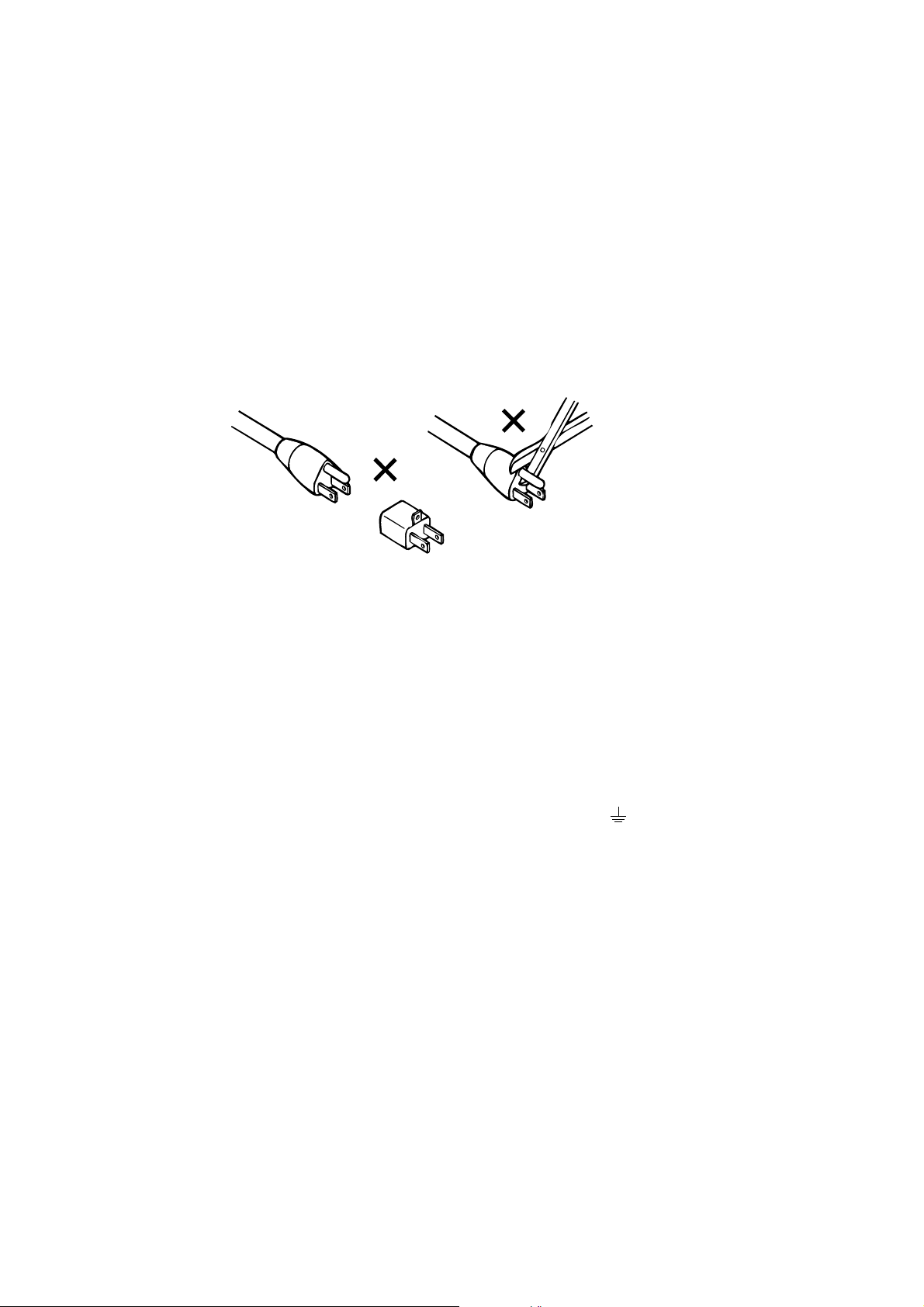
WARNING: Check that the units have been set to the correct supply voltage
and that the correct fuses have been installed. To reduce the risk of fire,
replace the fuses only with the same type and rating. Do not use a groundlifting adaptor and never cut the ground pin on the three-prong power plug.
UK
Connections for United Kingdom:
WARNING: THIS APPARATUS MUST BE EARTHED.
As the colours of the cores in the mains lead may not correspond with the
coloured markings identifying the terminals in your plug, proceed as
follows:
• The core which is coloured green and yellow must be connected to the terminal in
the plug which is marked with the letter E or by the earth symbol , or coloured
green or green and yellow.
• The core which is coloured blue must be connected to the terminal which is marked
with the letter N or coloured black.
• The core which is coloured brown must be connected to the terminal which is
marked with the letter L or coloured red.
EUROPEAN EMC
The 230V unit complies with the EMC requirements of EN 50081-1, EN
50082-1, prEN 55103-1 and -2 when installed in an E2 environment in
accordance with this manual.
Page 7

1-4
MAIN
IEC NOTICES
IMPORTANT SAFETY NOTICE
This unit complies with the safety standard IEC65. To ensure safe operation and to guard
against potential shock hazard or risk of fire, the following must be observed:
• Ensure the voltage selector is set to the correct mains voltage for your supply.
• Ensure fuses fitted are the correct rating and type as marked on the unit.
• The unit must be earthed by connecting to a correctly wired and earthed power outlet.
• The power cord supplied with this unit must be wired as follows:
Live—Brown Neutral—Blue Earth—Green/Yellow
IMPORTANT – NOTE DE SECURITE
Ce materiel est conforme à la norme IEC65. Pour vous assurer d'un fonctionnement sans danger et de prévenir
tout choc électrique ou tout risque d'incendie, veillez à observer les recommandations suivantes.
• Le selecteur de tension doit être placé sur la valeur correspondante à votre alimentation réseau.
• Les fusibles doivent correspondre à la valeur indiquée sur le materiel.
• Le materiel doit être correctement relié à la terre.
• Le cordon secteur livré avec le materiel doit être cablé de la manière suivante:
Phase—Brun Neutre—Bleu Terre—Vert/Jaune
WICHTIGER SICHERHEITSHINWEIS
Dieses Gerät entspricht der Sicherheitsnorm IEC65. Für das sichere Funktionieren des Gerätes und zur
Unfallverhütung (elektrischer Schlag, Feuer) sind die folgenden Regeln unbedingt einzuhalten:
• Der Spannungswähler muß auf Ihre Netzspannung eingestellt sein.
• Die Sicherungen müssen in Type und Stromwert mit den Angaben auf dem Gerät übereinstimmen.
• Die Erdung des Gerätes muß über eine geerdete Steckdose gewährleistet sein.
• Das mitgelieferte Netzkabel muß wie folgt verdrahtet werden:
Phase—braun Nulleiter—blau Erde—grün/gelb
GB
F
D
NORME DI SICUREZZA – IMPORTANTE
Questa apparecchiatura è stata costruita in accordo alle norme di sicurezza IEC 65. Per una perfetta sicurezza ed
al fine di evitare eventuali rischi di scossa êlettrica o d'incendio vanno osservate le seguenti misure di sicurezza:
• Assicurarsi che il selettore di cambio tensione sia posizionato sul valore corretto.
• Assicurarsi che la portata ed il tipo di fusibili siano quelli prescritti dalla casa costruttrice.
• L'apparecchiatura deve avere un collegamento di messa a terra ben eseguito; anche la connessione rete deve
avere un collegamento a terra.
• Il cavo di alimentazione a corredo dell'apparecchiatura deve essere collegato come segue:
Filo tensione—Marrone Neutro—Blu Massa—Verde/Giallo
AVISO IMPORTANTE DE SEGURIDAD
Esta unidad cumple con la norma de seguridad IEC65. Para asegurarse un funcionamiento
seguro y prevenir cualquier posible peligro de descarga o riesgo de incendio, se han de observar
las siguientes precauciones:
• Asegúrese que el selector de tensión esté ajustado a la tensión correcta para su alimentación.
• Asegúrese que los fusibles colocados son del tipo y valor correctos, tal como se marca en la unidad.
• La unidad debe ser puesta a tierra, conectándola a un conector de red correctamente cableado y puesto a
tierra.
• El cable de red suministrado con esta unidad, debe ser cableado como sigue:
Vivo—Marrón Neutro—Azul Tierra—Verde/Amarillo
VIKTIGA SÄKERHETSÅTGÄRDER!
Denna enhet uppfyller säkerhetsstandard IEC65. För att garantera säkerheten och gardera mot
eventuell elchock eller brandrisk, måste följande observeras:
• Kontrollera att spänningsväljaren är inställd på korrekt nätspänning.
• Konrollera att säkringarna är av rätt typ och för rätt strömstyrka så som anvisningarna på enheten föreskriver.
• Enheten måste vara jordad genom anslutning till ett korrekt kopplat och jordat el-uttag.
• El-sladden som medföljer denna enhet måste kopplas enligt foljande:
Fas—Brun Neutral—Blå Jord—Grön/Gul
I
E
S
BELANGRIJK VEILIGHEIDS-VOORSCHRIFT:
Deze unit voldoet aan de IEC65 veiligheids-standaards. Voor een veilig gebruik en om het gevaar van electrische
schokken en het risico van brand te vermijden, dienen de volgende regels in acht te worden genomen:
• Controleer of de spanningscaroussel op het juiste Voltage staat.
• Gebruik alleen zekeringen van de aangegeven typen en waarden.
• Aansluiting van de unit alleen aan een geaarde wandcontactdoos.
• De netkabel die met de unit wordt geleverd, moet als volgt worden aangesloten:
Fase—Bruin Nul—Blauw Aarde—Groen/Geel
NL
Page 8

2-1
MAIN
SECTION 2
INSTALLATION AND CALIBRA TION
2.1 Monitor Setup
Front Loudspeaker Arrangement
The SDU4 is designed for monitoring rooms with either two or three front
loudspeakers. The choice between using either two or three front loudspeakers
depends upon the distance between the Left and Right speakers, (how large the
stereo image is) and how the primary listening area is arranged relative to the
front sound image. In most cases, three front loudspeakers are recommended
with the center loudspeaker located immediately above or below the picture.
The center loudspeaker should be the same type as the left and right loudspeaker
to prevent audible shifts in tonal balance when effects are panned across the
front.
Two front loudspeakers may be adequate in monitoring situations where the
sound image is small to mid-sized (no more that eight feet apart) and the
listening area is relatively small and located on axis between the two
loudspeakers. In these situations, a “phantom” center can be used to reliably
localize the center channel information near the center of the picture.
The need for a center channel in video playback increases as the picture size is
reduced for a given playback situation. This is caused by the increased need to
localize dialogue to the center of the sound image when a smaller picture is
used. In the case where a phantom center (no center loudspeaker) is used, a
smaller picture increases the likelihood that off-axis seating will cause the
phantom to fall outside the picture area.
Left Center Right
Surround
Figure 2.1 Typical loudspeaker arrangement
Page 9

2-2
MAIN
Surround Loudspeakers
The surround loudspeakers are used to distribute a single channel of sound in
a diffuse field behind the viewer. The number of loudspeakers needed,
therefore, depends upon the size of the area to be covered. In smaller rooms,
such as those used for video production and home surround installations, two
loudspeakers generally provide sufficient coverage.
Equalization
The monitor system used with the SDU4 should have its electro-acoustical
frequency response adjusted to conform with international standards for widerange audio monitoring. This standardized equalization is encouraged, as it
allows program material to be interchanged between various monitoring
rooms and, ultimately, the viewer’s home, without apparent or objectionable
shifts in program equalization.
2.2 Mains Fuse and Voltage Selection
2.2.1 230V-Only SDU4
METAL CLIP INST ALLED
ON
UNUSED
CARRIER
OPEN THE
OPEN THE
DOOR
DOOR
Figure 2.2 Fuse compartment, 230V unit
FUSE
CARRIER
SIDE OF
TOP
INSTALL
FUSE
ACTIVE
FUSE
Open the fuse compartment door in the AC mains input connector with a small
flat blade screwdriver (see Figure 2.2), and check that the fuse has the correct
rating (T250mA 20mm time-lag). The fuse carrier must be inserted into the
compartment with the orientation as shown. Do not force the carrier into the
compartment. Damage will result.
Page 10

2.2.2 Multi-Voltage SDU4
MAIN
2-3
SPARE FUSE
(UPPER)
OPEN THE
DOOR
VOLTAGE SELECTOR
WHEEL
FUSE
ACTIVE
FUSE CARRIER
(LOWER)
FUSE
OCTAGONAL PEG
ROUND PEG
A2F4037
Figure 2.3 Fuse compartment, multi-voltage unit
Open the fuse compartment door in the AC mains input connector with a small
flat blade screwdriver (see Figure 2.3), and check that the fuse has the correct
rating. If necessary, rotate the selector drum until it displays the correct voltage
for the installation. (The drum may also be removed and replaced in the desired
position. It will only fit one way around.) Snap the fuse compartment door
closed .
For 85 to 132 Vac use 500 mA 1.25" slow-blow fuse.
For 187 to 264 Vac use T250 mA 20mm time-lag fuse.
2.3 Audio Connections
The SDU4 has been designed to interface with professional audio equipment
at commonly found studio operating levels. Connection to and from the unit
are made using standard 3-Pin XLR-type connectors. Both the input and
output stages are electronically balanced with pin 2 being positive and pin 3
being negative. For optimum immunity to radio-frequency interference, cable
shields should be connected to the shells of the XLR connectors, not to pin 1.
Page 11

2-4
MAIN
2.3.1 External Facilities Connector (J503)
J503
FEMALE D-CONNECTOR
+24V
+15V
-15V
DC GROUND
25
24
23
22
21
20
19
18
17
16
15
14
13
12
11
10
9
8
7
6
5
4
3
2
1
CHASSIS GROUND
REMOTE FADER WIPER
REMOTE FADER TOP
RIGHT TOTAL MONITOR
LEFT TOTAL MONITOR
DOLBY SURROUND
STEREO
MONO
LEFT MONITOR
CENTER MONITOR
RIGHT MONITOR
SURROUND MONITOR
DC GROUND
Figure 2.4 J503 connections
Connector J503 provides fixed level (500mV for Dolby level) monitoring points
for Lt and Rt and for L,C,R and S signals, and various remote control functions;
see Figure 2.4. For optimum immunity to radio-frequency interference all
cables connecting to J503 should be shielded with the shields connected to the
metal cover of the D-connector, not to pin 13 or 1.
2.4 Set-Up Options
To change any of these options (except surround delay), remove the front panel
(2 screws on top and 5 underneath) and the top cover (2 screws each side). All
Page 12

2-5
Mode Left Center Right Surround
MAIN
controls are on the right-hand module, Cat. No. 344, as shown in Figure 2.5.
Figure 2.5 Cat. No. 344
Center Speaker Switch
Switch S301 allows the SDU4 to be installed in monitoring rooms that have
either two loudspeakers (labeled “center speaker, no”) or three loudspeakers
(“yes”). The factory setting is “yes.”
While decoding Dolby Surround with the internal switch in the “yes position,
the decoder’s Center output signal is sent to the center loudspeaker, as normal.
With the internal switch in the “no” position, the decoder’s center output signal
is divided and added into the Left and Right output channels, preserving a
correct phantom center image.
With the SDU4 set to MONO mode, the internal center speaker switch determines
where the mono output signal will be sent. With S301 switched to the “yes”
position, the mono signal (a sum of Lt and Rt) is sent to the Center loudspeaker.
In the “no” position, the mono signal is reduced in level by 3dB and sent to the
Left and Right loudspeakers, thereby creating a phantom center image.
The following charts summarize the SDU4 output signals in the mono, stereo
and Dolby Surround operating modes. Lt and Rt refer to the input signals.
L,C,R, and S refer to the 2:4 decoder output signals.
SDU4 OUTPUTS CENTER—LOUDSPEAKER SWITCH SET TO “YES”
Mono — Lt & Rt — —
Stereo Lt — R t —
Dolby Surround L C R S
Page 13

2-6
Mode Left Right Surround
MAIN
SDU4 OUTPUTS—CENTER LOUDSPEAKER SWITCH SET TO “NO”
Mono .707 (Lt & Rt) .707 (Lt & Rt) —
Stereo Lt Rt —
Dolby Surround L + .707 (C) R + .707 (C) S
Wake-Up Mode Selection
The SDU4 can be set to default to any operating mode when power is first
turned on. This is set using the internal jumpers J1/J2/J3. See Figure 2.5. The
factory setting is Dolby Surround.
External Master Level Control Switch
An external master level control may be added by connecting an external 100K
linear potentiometer between pins 11, 12, and 1 on J503. (All three connections
are required.) The external level control must be engaged by switching the
internal switch S303 to the “remote” position. See Figure 2.6. The factory
setting is “local.”
TOP
WIPER
CUSTOMER SUPPLIED REMOTE
FADER POTENTIOMETER
100K LINEAR TAPER
(REAR VIEW)
DC GND
F3710A0C
Figure 2.6 External fader connected to J503
Surround Delay Setting
Figure 2.7 Cat. No. 150 delay adjustment
The Cat. No.150 decoder module has a single adjustment for setting the
surround delay. The delay can be adjusted in 10ms steps. It is helpful to
understand its purpose. The delay to the surround channel is used to reduce
the audibility of crosstalk by offsetting it in time behind the arrival of the main
signal coming from the front loudspeakers. This is particularly important with
dialog information, where crosstalk would be particularly bothersome when
heard coming from the rear. By delaying the surround channel so that common
crosstalk information arrives at the listener about 15-20 ms after the main front
signal, the audibility of the crosstalk signal is substantially reduced.
BELDEN 8771
OR EQUIVALENT
CONNECTOR
MOUNTING SCREW
Delay setting
2
TO PIN 11
TO PIN 12
TO PIN 1
113
J503
Page 14

2-7
MAIN
The delay setting can be estimated by using the following method:
1. Estimate the distance between the primary listening location and the
nearest surround loudspeaker, in feet. If the metric system is used,
convert the distance from meters to feet by multiplying by three (3).
2. Estimate the distance from the primary listening location to the front
center loudspeaker, in feet. If the metric system is used, multiply the
distance by three (3) to convert distance from meters to feet.
3. Subtract the distance measured in step 1 above from the distance measured
in step 2, then add 20 and round the answer to the nearest 10. The result
is the delay time, in milliseconds.
For example:
The listening location is 10 feet (3.3 meters) from the surround speakers.
The selected seat is 20 feet (6.6 meters) from the front center speaker.
The delay is set for (20-10) + 20 = 30 milliseconds, switch setting 1.
The delay time for each switch setting is:
20ms ______ 0
30ms ______ 1
40ms ______ 2
50ms ______ 3
60ms ______ 4
and so on....
150ms _____ 13
As the SDU4 will frequently be used in small rooms, it is likely that the delay
will always be set to the minimum position (0).
2.5 Input Level Setting
LEFT
RIGHT
LO HI LO HI
INPUT
Figure 2.8 LED calibration meter and input adjustments
Page 15

2-8
MAIN
The SDU4 contains two four element LED calibration indicators for setting of
input level.
The two input level potentiometers are set so that reference tone from the signal
source, representing the studio’s operating level, is equal to the SDU4’s internal
operating level.
Any level between –8 dBr and +8 dBr can be set to correspond with the internal
operating level. This is indicated by the two green LEDs being equally
illuminated. (0dBr = 0.775V rms.)
2.6 Output Level Setting
The SDU4 contains an internal pink noise generator that allows easy setting of
the output level controls and the verification of correct operation of the monitor
system. (Always select Dolby Surround mode before using the pink noise
generator. If unintentionally you operate the toggle switch in one of the other
modes, return it to the OFF position and select Dolby Surround to reset the
internal logic.)
The generator has two modes of operation—manual and automatic—as selected
by the front panel toggle switch. With the switch in the center, or “off” position,
the SDU4 functions normally. In the DOWN, or manual, position, wide-band
pink noise can be manually stepped to each output channel using the “noise
sequence” buttons. The manual position is typically used during initial set-up,
where correct monitor equalization is being set using a calibrated microphone
and real-time analyzer. In the UP, or auto, position the pink noise is automatically
sequenced through the output channels in two different patterns:
With the LCRS button pushed, wide-band pink noise is sequenced through all
four outputs, as done with the manual mode, except no operator intervention
is required. This is especially useful for verifying quickly correct monitor
operation.
With the CSCS button pushed, the pink noise switches between the center and
surround channels only. This allows easy and audible verification of surround
level settings by providing an audible comparison with the center-front setting.
In this mode, the pink noise is filtered to eliminate all but the mid-band
frequencies. This bandlimiting helps prevent misjudging of absolute level
caused by frequency response variations between the front and surround
speakers.
Page 16

PINK NOISE
MAIN
AUTO
OFF
2-9
MANUAL
CSCS
NOISE SEQUENCE
LCRS
RCL SOUTPUT
Figure 2.9 Pink-noise calibrate functions
Output Level Adjustments
Output potentiometers are provided so that the decoder output level can be
matched to the monitor system. Typically, the SDU4 output level is set using
the internal pink noise source.
The front panel master level control is set to the “∇” mark (2 o’clock). Then the
SDU4 output trims, (or alternatively, the level controls on the power amplifiers)
are set so that the sound pressure level in the primary listening area is adjusted
to the recommended level (usually 85dBc) with one channel at a time being
driven with wide-band pink noise.
In cases where the SDU4 outputs are routed though a switching system and the
outputs from other devices are connected to the power amplifiers, set the SDU4
outputs to an established house reference level (+4dBr, for instance) and make
the final monitor level adjustments at the power amplifiers.
Master Level Control
The SDU4 contains a four channel master level control that allows the overall
listening level to be adjusted up or downward without upsetting the individual
channel balance. The “∇” position should be considered the normal operating
level.
Page 17

3-1
MAIN
SECTION 3
OPERATION
3.1 Operating Modes and Applications
The SDU4 has three modes of normal operation: Mono, Stereo and Dolby
Surround.
Mono
The mono mode combines the Lt and Rt input signals into a single channel
and routes it to the Center loudspeaker, if the internal switch S301 is in the
"yes" position. If the internal switch is in the "no" position, the mono sum of
Lt and Rt is sent to the Left and Right loudspeakers at a reduced level,
thereby creating a correct phantom center image.
Stereo
The stereo mode is provided for conventional stereophonic reproduction of
the input Lt and Rt signals. This mode, in effect, provides an electronic
bypass, leaving the input buffers, master level control and line amplifiers in
the signal path.
The position of the internal Center speaker yes/no switch has no effect in
the stereo mode; there is no output from the Center loudspeaker in either
case.
Dolby Surround
The Dolby Surround mode provides full decoding of the two channel input
material using the internal Cat. No. 150 2:4 channel surround decoder
module.
3.2 Detailed Applications
Broadcast
Broadcast applications include evaluation of transmission masters originally
recorded for theatrical release. Additionally, selected television programs
are now being produced using the Dolby Surround encoding format.
Broadcast of feature films originally released with Dolby encoded
soundtracks are commonplace. The stereo audio tracks on the master
videotapes are normally direct transfers of the original Dolby theatrical
release soundtrack, and therefore surround information is included within
the broadcast audio.
Page 18

3-2
MAIN
The matrix format used on Dolby soundtracks is compatible with both
monophonic and conventional stereo playback.
Many home viewers have purchased Dolby Surround decoding equipment
for use during playback of prerecorded videotape or videodisk program
material. These consumer grade decoders are being manufactured by the
many companies who are licensed by Dolby Laboratories. Viewers are
finding that the Dolby Surround decoders are also capable of effectively
decoding broadcasts of Dolby films and Dolby Surround productions. The
SDU4 gives the broadcast station a means of monitoring the correct spatial
decoding of this material in the professional broadcast environment.
The SDU4 is simply installed in the monitor system, typically between the
stereo replay machine or stereo program buss. Its output is used to drive the
monitor system’s power amplifiers, either directly or through an audio
routing system. Surround encoded material will usually be decoded using
the Dolby Surround mode; however, it may be evaluated for conventional
stereo and mono compatibility as well. Proper decoding of Dolby Surround
encoded material is, of course, the preferred way of evaluating the overall
quality of the material. All stereo program material, regardless of whether
it is specifically surround encoded or not, can be evaluated for compatibility
in mono, stereo and surround playback.
Conventionally recorded stereo material, i.e., originally recorded for two
loudspeaker playback, may be checked for acceptability using the Dolby
Surround mode. In this case, center and surround channels will be extracted
from the stereo mix as if they were specifically encoded as such.
Note: If a center loudspeaker is not used, i.e., the internal Center speaker
switch S301 is in the “no” position, the decoded center output is re-summed
with the left and right decoder output signals, giving effectively the same
front stereo image as with normal stereo playback. In this case, the decoder
will extract the phase-difference information from the stereo input material
and send it to the rear loudspeakers.
As most conventional stereo material contains some valid phase difference
information, due to the microphone techniques, the reproduction of this
phase difference information to the rear of the viewer will usually lead to an
overall pleasing effect. On the other hand, artificially induced phasedifferences, created either by alignment errors or by some special effects
processors (such as stereo synthesizers) can cause erroneous and
inappropriate sound elements at the rear of the viewer. Conventional stereo
material may be evaluated for compatible playback using the Dolby Surround
mode.
In audio post-production environments, it is recommended that all stereo
material be evaluated through the SDU4 in the Dolby Surround mode as a
means of verifying mono compatibility. Conventional monophonic
recording, i.e., equal phase at equal level, can be considered a subset of the
Dolby Surround encoding matrix, as its occurrence will be reproduced as
Page 19

3-3
MAIN
center channel information. This, in effect, will cause the mono-compatible
elements of the mix to appear to always come from the center of the picture.
On the other hand, the incompatible elements (those that would cancel if the
two input channels were summed) would be reproduced around and
behind the listener. This spatial effect is useful as it instantly alerts sound
mixers to compatibility problems should inappropriate elements, such as
on-screen effects, or dialogue, suddenly appear in the rear.
Music Recording For Dolby Encoded Films
Music studios will find the SDU4 very useful when recording material
intended for integration into Dolby encoded soundtracks as it provides
accurate monitoring of two- or three-channel material in its final dimensional
perspective.
Typically, the SDU4 would be installed into the monitor system during the
music mix. Three equally balanced loudspeakers would be used in the front
driven by the L, C and R outputs, with the surround channel optionally used
to drive two or more speakers, wired as mono, in the rear.
The music pre-mix is usually recorded as three tracks with assignment
being made into L C and R tracks. Generally, no surround track is recorded
in advance. The three tracks can be recorded directly from the console mix
buss, but the discrete center track must be made into a “phantom”. This
requires the center track to be added back into the L and R channels at
precisely –3 dB into each. From this point, these two channels are sent to the
SDU4 Lt and Rt inputs for decoding into the spatially correct L,C,R and S
channels.
This fairly simple procedure allows the studio to simulate the action of the
Dolby encoder in respect to the generation of the center channel. It is not
possible, however, to pre-record an accurate discrete surround track using
this technique. Encoding of the surround channel requires the use of the
surround encoder due to the precise nature of the phase matching necessary
between the center and surround channels.
The three-track music mix would typically be transferred to magnetic film
and, subsequently, matched to the edited picture. In the film re-recording
studio it would be added with dialogue and effects keeping the same spatial
imaging characteristics.
Surround Productions
The SDU4 has been designed to interface with the Dolby Model SEU4
Surround encoding unit. Post-production facilities contemplating the
production of surround encoded programs should consider the installation
of the SDU4 and the establishment of a correct monitoring environment as
the first step in equipping for future surround productions.
Page 20

MONITOR POINTS
J503
LT
RT
21
23
LEFT TOTAL
1 = CHASSIS
2 = HI
3 = LO
4 = CHASSIS
RIGHT TOTAL
CAT.NO.344
CAT. 150
4
3
J501
2
3
1
J502
2
3
1
Z
22
Y
21
MONO
CSCS
STEREO
LCRS
DOLBY
SURROUND
VAR.
ATTEN.
VAR.
ATTEN.
POWER-ON
MODE SELECT
NC
NC
NC
INPUT
AMP
AUTO
OFF
MANUAL
INPUT
AMP
SURROUND
STEREO
DOLBY
MONO
AND
MODE
NOISE
SEQUENCER
SELECTION
LOGIC
STEREO
MONO
DOLBY
P
11
8
7M6
J503
REMOTE MODE SELECT
NOISE
SURROUND
PINK
GEN
LEVEL
METERS
(LEDS)
10
E
7
5
L
LT
2
5
C
1
RT R
14 15
6
4
1
S
SURRMONO
A
C
SDU4 BLOCK DIAGRAM
A3B3708 REV 2
MUTE
L
C
LOOP
SWITCH
R
S
J503
5
K
VCA
4
J
CENTER
SPKR SW
VCA
3
H
VCA
2
F
VCA
MONO
(CSCS FLASH)
LED
DRIVER
&
FLASHER
STEREO
(LCRS FLASH)
DOLBY
SURROUND
PIN 1
CONTROL
VOLTAGE GEN
FADER
SELECT
1
TO REMOTE FADER
LEVEL
TRIM
LEVEL
TRIM
LEVEL
TRIM
LEVEL
TRIM
19
J503
12
LOCAL
FADER
REMOTE
LEFT
P501
V
OUTPUT
AMP
OUTPUT
AMP
OUTPUT
AMP
OUTPUT
AMP
18
U
17
T
16
S
15
2
3
1
CENTER
P502
2
3
1
RIGHT
P503
2
3
1
SURROUND
P504
2
3
1
4-1
BLOCK DIAGRAM
SECTION 4
W20
11
 Loading...