

Dolby Laboratories DMA 8 Installation Manual

Film-Tech
The information contained in this Adobe Acrobat pdf
file is provided at your own risk and good judgment.
These manuals are designed to facilitate the
exchange of information related to cinema
projection and film handling, with no warranties nor
obligations from the authors, for qualified field
service engineers.
If you are not a qualified technician, please make no
adjustments to anything you may read about in these
Adobe manual downloads.
www.film-tech.com

Model DMA™8
Digital Media Adapter
™
Installation Manual
Issue 1 Part Number 91802

Corporate Headquarters
Dolby Laboratories, Inc.
100 Potrero Avenue
San Francisco, CA 94103-4813
Telephone 415-558-0200
Fax 415-863-1373
www.dolby.com/
European Headquarters
Dolby Laboratories, Inc.
Wootton Bassett
Wiltshire, SN4 8QJ, England
Telephone (44) 1793-842100
Fax (44) 1793-842101
Model DMA™8 Installation Manual
Dolby Laboratories, Inc.
Dolby and the double-D symbol are registered trademarks of Dolby Laboratories. Digital Media Adapter, DMA, and Surround EX are
trademarks of Dolby Laboratories. All other trademarks remain the property of their respective owners.
2002 Dolby Laboratories, Inc., all rights reserved.
S02/14328 Issue 1 Part Number 91802
ii

Model DMA™8 Installation Manual
Table of Contents
Chapter 1 Introduction
Regulatory Notices
Chapter 2 Installation
2.1 Unpacking..............................................................................................2-1
2.2 Equipment Required.............................................................................2-1
2.3 Mounting—Proper Grounding..............................................................2-2
2.4 Fuse Information...................................................................................2-2
Check Main Fuse......................................................................................2-2
Internal Fuse .............................................................................................2-3
Mains Power Wiring.................................................................................2-3
2.5 Digital Audio Sources...........................................................................2-4
Professional Interface Standards for Digital Audio..................................2-4
Consumer Interface Standards for Digital Audio.....................................2-5
Multiple Sources—Conversion Between Interface Standards .................2-5
2.6 Connections ..........................................................................................2-6
2.6.1 Digital Media Automation Connector ......................................................2-6
2.6.2 RS-232 Serial Control Port.......................................................................2-7
2.6.3 Serial Data In/Out—Auto Dolby Digital Surround EX Control ..............2-7
2.7 Wiring Diagrams
Wiring to CP500...................................................................................................2-8
Wiring to CP65/DA20..........................................................................................2-9
Wiring to CP55/DA20........................................................................................2-10
Wiring to CP45/DA20........................................................................................2-11
Wiring to CP200/DA20......................................................................................2-12
iii

Model DMA™8 Installation Manual
Chapter 3 Setup
3.1 Setup Software......................................................................................3-1
3.2 Running Setup.......................................................................................3-2
3.2.1 Main Screen..............................................................................................3-2
3.2.2 Change Settings ........................................................................................3-3
3.2.3 Change Settings/Advanced Button...........................................................3-4
Miscellaneous Tab....................................................................................3-4
Channel Assignments Tab........................................................................3-5
Program Selection Tab .............................................................................3-5
3.2.4 Change Settings/View Log.......................................................................3-6
3.2.5 Change Settings/Update Software............................................................3-7
Chapter 4 Operation
4.1 Front-Panel Switches............................................................................4-1
4.2 Power .....................................................................................................4-1
4.3 Surround Delay .....................................................................................4-1
Chapter 5 Technical Reference
5.1 DMA8 Specifications.............................................................................5-1
5.2 DMA8 Repair..........................................................................................5-2
5.3 Serial Port Command Set.....................................................................5-2
5.4 Connectors............................................................................................5-3
5.4.1 Rear-Panel Connector Descriptions and Types........................................5-3
5.4.2 Digital Media Automation Connector ......................................................5-3
5.4.3 Analog Audio In/Out Connector ..............................................................5-4
5.4.4 4x AES In Connector................................................................................5-5
5.4.5 Serial Ports (Front and Rear), RS-232 Connectors ..................................5-6
5.4.6 CP and DA Control Automation Connectors ...........................................5-6
5.4.7 Automation Connections—CP55 with Cat. No. 321................................5-7
iv

Model DMA™8 Installation Manual
List of Figures
Figure 2-1 Use Star Washers........................................................................................................2-2
Figure 2-2 Checking the Main Fuse .............................................................................................2-3
Figure 2-3 Rear-Panel View.........................................................................................................2-6
Figure 3-1 Open Device Screen ...................................................................................................3-2
Figure 3-2 Main Screen ................................................................................................................3-2
Figure 3-3 Settings Screen............................................................................................................3-3
Figure 3-4 Change Settings/Advanced—Miscellaneous Tab.......................................................3-4
Figure 3-5 Change Settings/Advanced—Channel Assignments Tab...........................................3-5
Figure 3-6 Change Settings/Advanced—Program Selection Tab ................................................3-5
Figure 3-7 Change Settings/View Log—Event Log ....................................................................3-6
Figure 3-8 Change Settings/View Log—Error Log .....................................................................3-6
Figure 3-9 Change Settings/Update Software ..............................................................................3-7
List of Tables
Table 2–1 Examples of Available Balanced ↔ Unbalanced Adapters........................................2-6
Table 5–1 Serial Port Command Strings ......................................................................................5-2
Table 5–2 Rear-Panel Connector Descriptions and Types...........................................................5-3
Table 5–3 Digital Media Connector Pinout..................................................................................5-3
Table 5–4 Analog Audio In/Out Connector Pinout......................................................................5-4
Table 5–5 4x AES In Connector Pinout .......................................................................................5-5
Table 5–6 Serial Ports Pinout .......................................................................................................5-6
Table 5–7 CP and DA Control Connectors Pinout.......................................................................5-6
Table 5–8 CP55 with Cat. No. 321 Installed................................................................................5-7
v

Model DMA™8 Installation Manual
Chapter 1
Introduction
Thank you for purchasing the Dolby® Model DMA™8 Digital Media Adapter™. This
new cinema audio tool, a direct result of Dolby’s mission to develop technologies that
improve sound recording and reproduction, allows you to stay at the forefront of
quality entertainment presentation now and into the future.
The DMA8 expands the use of a cinema beyond traditional film applications. It
equips any theatre for a wide variety of uses, providing capabilities far beyond that of
simply showing movies to the general public. The DMA8 enables theatres to provide
audio solutions to today’s alternative programming challenges, such as pay-per-view
events and digital broadcasting.
The unit provides a straightforward interface with existing Dolby cinema processors
CP650, CP500, CP65, CP55, CP45, and CP200. High-quality audio can be presented
from a wide variety of the audio sources:
• High-definition video server
• PCM
• DVD
• Dolby Digital (consumer, non-film-based)
• Broadcast
• Dolby E
The DMA8 is compatible with existing theatre automation. Its accommodation for
multiple formats and future upgrades make it an essential tool for an evolving digital
cinema market.
When the DMA8 is in Film mode, standard six-channel analog signals from any
source, such as a DA20, are routed through the DMA8 to the six-channel input of a
cinema sound processor. In Digital Media mode, the DMA8 decodes and routes
signals from a variety of non-film sources (PCM, DVD, broadcast, Dolby E, and with
an optional Cat. No. 767 card, SDI) to the existing cinema sound processor. The
DMA8 software enables the user to select programs for applications that contain
multiple audio formats.
Like all Dolby cinema sound products, the DMA8 is fully supported by hundreds of
factory-trained technicians worldwide, on-call emergency assistance, and the most
experienced distributor network in the industry.
1-1
Model DMA™8 Installation Manual Introduction
Regulatory Notices
FCC
This equipment has been tested and found to comply with the limits for a Class A digital device,
pursuant to Part 15 of the FCC Rules. These limits are designed to provide reasonable protection
against harmful interference when the equipment is operated in a commercial environment. This
equipment generates, uses, and can radiate radio frequency energy and, if not installed and used in
accordance with this instruction manual, may cause harmful interference to radio communications.
Operation of this equipment in a residential area is likely to cause harmful interference in which case
the user will be required to correct the interference at his or her own expense.
Canada
This Class A digital apparatus complies with Canadian ICES-003.
UL
WARNING: Troubleshooting must be performed by a trained technician. Do not
attempt to service this equipment unless you are qualified to do so.
Check that the correct fuses have been installed. To reduce the risk of fire, replace
only with fuses of the same type and rating.
Exposed portions of the power supply assembly are electrically “hot”. To reduce the risk of
electrical shock, the power cord MUST be disconnected when the power supply assembly is
removed.
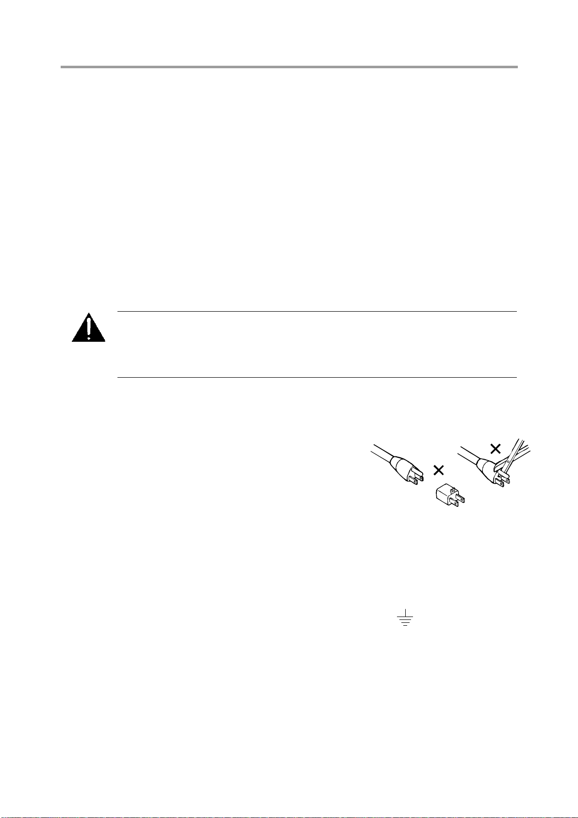
The ground terminal of the power plug is connected
directly to the chassis of the unit. For continued protection
against electric shock, a correctly wired and grounded
(earthed) three-pin power outlet must be used. Do not use
a ground-lifting adapter and never cut the ground pin on
the three-prong plug.
UK
The power cord, Dolby Part No. 92021, supplied for use in Europe is not suitable for use in the
UK. To use the cord in the UK, cut off the CEE7/7 plug and replace with an approved
BS 1363 13A plug:
• The core that is coloured green and yellow must be connected to the terminal in
the plug identified by the letter E, or by the earth symbol , or coloured green,
or green and yellow.
• The core that is coloured blue must be connected to the terminal that is marked
with the letter N or coloured black.
• The core that is coloured brown must be connected to the terminal that is marked
with the letter L or coloured red.
• This apparatus must be earthed.
1-2
Model DMA™8 Installation Manual Introduction
EU
This equipment complies with the EMC requirements of EN55103-1 and EN55103-2 when operated in an E2
environment in accordance with this manual.
IMPORTANT SAFETY NOTICE
This unit complies with the safety standard EN60065. The unit shall not be exposed to dripping or splashing and no objects filled with liquids,
such as coffee cups, shall be placed on the equipment. To ensure safe operation and to guard against potential shock hazard or risk of fire, the
following must be observed:
o Ensure that your mains supply is in the correct range for the input power requirement of the unit.
o Ensure fuses fitted are the correct rating and type as marked on the unit.
o The unit must be earthed by connecting to a correctly wired and earthed power outlet.
oThe power cord supplied with this unit must be wired as follows:
Live—Brown Neutral—Blue Earth—Green/Yellow
IMPORTANT – NOTE DE SECURITE
Ce materiel est conforme à la norme EN60065. Ne pas exposer cet appareil aux éclaboussures ou aux gouttes de liquide. Ne pas poser d'objets
remplis de liquide, tels que des tasses de café, sur l'appareil. Pour vous assurer d'un fonctionnement sans danger et de prévenir
tout choc électrique ou tout risque d'incendie, veillez à observer les recommandations suivantes.
o Le selecteur de tension doit être placé sur la valeur correspondante à votre alimentation réseau.
o Les fusibles doivent correspondre à la valeur indiquée sur le materiel.
o Le materiel doit être correctement relié à la terre.
o Le cordon secteur livré avec le materiel doit être cablé de la manière suivante:
Phase—Brun Neutre—Bleu Terre—Vert/Jaune
WICHTIGER SICHERHEITSHINWEIS
Dieses Gerät entspricht der Sicherheitsnorm EN60065. Das Gerät darf nicht mit Flüssigkeiten (Spritzwasser usw.) in Berührung kommen; stellen
Sie keine Gefäße, z.B. Kaffeetassen, auf das Gerät. Für das sichere Funktionieren des Gerätes und zur Unfallverhütung (elektrischer Schlag,
Feuer) sind die folgenden Regeln unbedingt einzuhalten:
o Der Spannungswähler muß auf Ihre Netzspannung eingestellt sein.
o Die Sicherungen müssen in Typ und Stromwert mit den Angaben auf dem Gerät übereinstimmen.
o Die Erdung des Gerätes muß über eine geerdete Steckdose gewährleistet sein.
o Das mitgelieferte Netzkabel muß wie folgt verdrahtet werden:
Phase—braun Nulleiter—blau Erde—grün/gelb
NORME DI SICUREZZA – IMPORTANTE
Questa apparecchiatura è stata costruita in accordo alle norme di sicurezza EN60065. Il prodotto non deve essere sottoposto a schizzi, spruzzi e
gocciolamenti, e nessun tipo di oggetto riempito con liquidi, come ad esempio tazze di caffè, deve essere appoggiato sul dispositivo. Per una
perfetta sicurezza ed al fine di evitare eventuali rischi di scossa êlettrica o d'incendio vanno osservate le seguenti misure di sicurezza:
o Assicurarsi che il selettore di cambio tensione sia posizionato sul valore corretto.
o Assicurarsi che la portata ed il tipo di fusibili siano quelli prescritti dalla casa costruttrice.
o L'apparecchiatura deve avere un collegamento di messa a terra ben eseguito; anche la connessione rete deve
avere un collegamento a terra.
o Il cavo di alimentazione a corredo dell'apparecchiatura deve essere collegato come segue:
Filo tensione—Marrone Neutro—Blu Massa—Verde/Giallo
AVISO IMPORTANTE DE SEGURIDAD
Esta unidad cumple con la norma de seguridad EN60065. La unidad no debe ser expuesta a goteos o salpicaduras y no deben colocarse sobre el
equipo recipientes con liquidos, como tazas de cafe. Para asegurarse un funcionamiento seguro y prevenir cualquier posible peligro de descarga o
riesgo de incendio, se han de observar las siguientes precauciones:
o Asegúrese que el selector de tensión esté ajustado a la tensión correcta para su alimentación.
o Asegúrese que los fusibles colocados son del tipo y valor correctos, tal como se marca en la unidad.
o La unidad debe ser puesta a tierra, conectándola a un conector de red correctamente cableado y puesto a tierra.
o El cable de red suministrado con esta unidad, debe ser cableado como sigue:
Vivo—Marrón Neutro—Azul Tierra—Verde/Amarillo
VIKTIGA SÄKERHETSÅTGÄRDER!
Denna enhet uppfyller säkerhetsstandard EN60065. Enheten får ej utsättas för yttre åverkan samt föremål innehållande vätska, såsom
kaffemuggar, får ej placeras på utrustningen." För att garantera säkerheten och gardera mot eventuell elchock eller brandrisk, måste följande
observeras:
o Kontrollera att spänningsväljaren är inställd på korrekt nätspänning.
o Konrollera att säkringarna är av rätt typ och för rätt strömstyrka så som anvisningarna på enheten föreskriver.
o Enheten måste vara jordad genom anslutning till ett korrekt kopplat och jordat el-uttag.
o El-sladden som medföljer denna enhet måste kopplas enligt foljande:
Fas—Brun Neutral—Blå Jord—Grön/Gul
BELANGRIJK VEILIGHEIDS-VOORSCHRIFT:
Deze unit voldoet aan de EN60065 veiligheids-standaards. Dit apparaat mag niet worden blootgesteld aan vocht. Vanwege het risico dat er
druppels in het apparaat vallen, dient u er geen vloeistoffen in bekers op te plaatsen. Voor een veilig gebruik en om het gevaar van electrische
schokken en het risico van brand te vermijden, dienen de volgende regels in acht te worden genomen:
o Controleer of de spanningscaroussel op het juiste Voltage staat.
o Gebruik alleen zekeringen van de aangegeven typen en waarden.
o Aansluiting van de unit alleen aan een geaarde wandcontactdoos.
o De netkabel die met de unit wordt geleverd, moet als volgt worden aangesloten:
Fase—Bruin Nul—Blauw Aarde—Groen/Geel
GB
F
D
I
E
S
NL
1-3

2.1 Unpacking
Before unpacking the DMA™8, inspect the outer carton for shipping damage. If the
carton shows damage, inspect the unit in those areas.
Carefully remove the unit from its carton, remove the plastic wrapping, and place on
a flat surface. Look for the following items, which are packed with the DMA8:
• PC setup software
• Power cord
Model DMA™8 Installation Manual
Chapter 2
Installation
• Spare fuse
2.2 Equipment Required
A PC running Windows® 98 or later is required for proper installation of the DMA8:
2-1
Model DMA™8 Installation Manual Installation
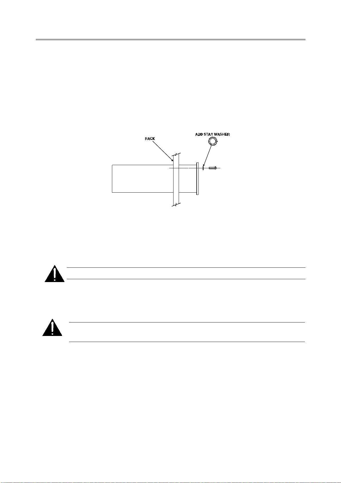
2.3 Mounting—Proper Grounding
Various types of noise may be present in and around the projection booth without
audible signs of anything being wrong. Proper mounting and wiring of booth
equipment helps ensure trouble-free performance.
We recommend that star washers be installed on all rack-mounting screws to ensure
good ground contact. This helps prevent electrical noise problems.
Figure 2-1 Use Star Washers
The DMA8 must be mounted in the same rack as the cinema processor to avoid
potential problems with ground loops, radiated interference, and so on.
WARNING: Follow all local codes and regulations covering electrical wiring.
2.4 Fuse Information
WARNING: To reduce the risk of fire, replace fuses only with the same type
and rating.
The DMA8 uses a universal switching power supply that handles the full range of
nominal mains voltages between 100 and 240 VAC, and any frequency between
50 and 60 Hz.
Check Main Fuse
The main fuse rating is:
T 1A L (time-lag, 1 amp, 250 V, 20 mm, low breaking capacity) for all operating
voltages.
2-2
 Loading...