

Dolby Laboratories CP500-D, CP500-300, CP500-SR, CP500-70, CP500 Installation And Alignment Manual
Page 1

Film-Tech
The information contained in this Adobe Acrobat pdf
file is provided at your own risk and good judgment.
These manuals are designed to facilitate the
exchange of information related to cinema
projection and film handling, with no warranties nor
obligations from the authors, for qualified field
service engineers.
If you are not a qualified technician, please make no
adjustments to anything you may read about in these
Adobe manual downloads.
www.film-tech.com
Page 2

Model CP500
Digital Cinema Sound
Processor
Installation and Alignment
Issue 5 Part No. 91371
Page 3

Installation and Alignment Manual
For
Model CP500
Digital Cinema Sound Processor
Dolby Laboratories Incorporated
U.S.A. 100 Potrero Avenue, San Francisco, CA 94103
Tel: 415-558-0200; Fax: 415-863-1373, www.dolby.com
U.K. Wootton Bassett, Wiltshire SN4 8QJ
Tel: (44) 1793-842100; Fax: (44) 1793-842101
Equipment manufactured by Dolby Laboratories is warranted against defects in materials and
DISCLAIMER OF WARRANTIES:
workmanship for a period of one year from the date of purchase.
merchantability or fitness for a particular purpose.
LIMITATION OF LIABILITY:
negligence or otherwise shall not exceed the cost of repair or replacement of the defective components and under no circumstances shall
Dolby Laboratories be liable for incidental, special, direct, indirect or consequential damages (including but not limited to damage to software
or recorded audio or visual material), or loss of use, revenue or profit even if Dolby Laboratories or its agents have been advised, orally or in
writing, of the possibility of such damages.
Dolby and the double-D symbol are registered trademarks of Dolby Laboratories.
Windows 95 is a trademark of Microsoft Corporation
Digital decoding covered by the following U.S. patents: 4,790,016, 4,914,701, 4,799,260 4,941,177, 5,109,417, 5,142,656, 5,230,038,
5,274,740, 5,297,236, 5,357,594, 5,463,424, 5,583,962, 5,608,805, and other worldwide patents granted and pending.
There are no other express or implied warranties and no warranty of
It is understood and agreed that Dolby Laboratories’ liability whether in contract, in tort, under any warranty, in
©1998 Dolby Laboratories Inc.
ISSUE 5
Software v 1.30
S98/11507/12003
Dolby Part No. 91371
Page 4

SECTION 1 INTRODUCTION
1.1 About the Dolby CP500......................................................................1-1
1.2 Hardware Configurations Available....................................................1-1
CP500-D........................................................................................1-1
CP500-300.....................................................................................1-1
CP500-SR......................................................................................1-2
CP500-70.......................................................................................1-2
1.3 About This Manual..............................................................................1-2
1.4 Specifications ......................................................................................1-3
1.5 Regulatory Notices..............................................................................1-5
FCC ...............................................................................................1-5
UL..................................................................................................1-5
UK .................................................................................................1-5
IEC.................................................................................................1-5
SECTION 2 EQUIPMENT REQUIRED
TABLE OF CONTENTS
SECTION 3 INSTALLATION AND JUMPERS
3.1 Replacing an Existing Sound System..................................................3-1
3.1.1 Before playing the film:........................................................3-1
3.1.2 While playing the film:.........................................................3-1
3.1.3 Disconnect the old system....................................................3-1
3.2 Mount the CP500.................................................................................3-2
3.3 Connect the CP500..............................................................................3-2
3.3.1 Connect Motor Start Relays ................................................3-3
3.3.2 Connect Remote Controls ...................................................3-3
3.3.3 Connection of Solar Cell Boards.........................................3-4
3.4 Check and Set Jumpers........................................................................3-6
Cat. No. 661 Optical Pre-amplifier Card (Analog
Soundtracks)......................................................................3-6
Cat. No. 681 Analog Switch Card.....................................3-6
Cat. No. 682 Analog Output Card.....................................3-7
Cat. No. 683 Crossover Card (Optional)...........................3-8
3.5 Install Circuit Cards - Card Descriptions ..........................................3-10
Model CP500-D ..........................................................................3-10
Cat. No. 222SR/A Module..............................................3-10
Cat. No. 661 Optical Preamplifier Card..........................3-10
Cat. No. 681 Input Switch Card ......................................3-10
Cat. No. 675A Digital Signal Processing Cards (2)........3-10
Cat. No. 685 6-Channel Analog to Digital Converter
Card .................................................................................3-10
Cat. No. 662 6-Channel Digital to Analog Converter
and Voltage Controlled Amplifier Card..........................3-10
Cat. No. 682 Analog Output Card...................................3-10
Cat. No. 684 System Controller Card..............................3-10
Cat. No. 683 Crossover Card (Optional).........................3-11
Page 5

ii
Dolby Digital Soundtrack Processing System............................. 3-11
Cat. No. 670 Video Front-end Card............................................ 3-11
Cat. No. 671 DSP Cards (2)........................................................ 3-11
Cat. No. 673 System Services Card ............................................ 3-11
Cat. No. 675A Digital Signal Processing Card........................... 3-11
Cat. No. 680 Bit Rate Converter Card ........................................ 3-11
Model CP500-D/300............................................................................... 3-11
Model CP500-SR ....................................................................................3-11
Model CP500-70..................................................................................... 3-11
Cat. No. 222A Modules (2)......................................................... 3-11
Cat. No. 669 Adapter Card..........................................................3-11
Cat. No. 685 6-Channel Analog to Digital Converter
Card............................................................................................. 3-11
3.6 Bypass Power Wiring....................................................................................3-12
3.7 Power On.......................................................................................................3-13
3.7.1 Hum and Other Noise Problems.....................................................3-14
Fold-Out Drawings:
Card Locations
CP500 Wiring
SECTION 4 FRONT PANEL and ALIGNMENT OVERVIEW
4.1 The CP500 Front Panel................................................................................. 4-1
4.1.1 Soft Keys: SK1 to SK8..................................................................4-1
4.1.2 Hard Keys....................................................................................... 4-1
Formats........................................................................................ 4-1
Menu............................................................................................4-1
Cancel..........................................................................................4-3
OK............................................................................................... 4-3
Exit.............................................................................................. 4-3
4.1.3 Other Controls and Indicators:....................................................... 4-3
4.2 System Password........................................................................................... 4-4
4.3 Aligning the B-Chain.................................................................................... 4-5
SECTION 5 B-CHAIN ALIGNMENT
5.1 Check Theater Equipment............................................................................. 5-1
Amplifiers....................................................................................5-1
Air-conditioning.......................................................................... 5-2
5.2 Preparing for Room Equalization.................................................................. 5-2
Using a Microphone Multiplexer with the CP500...................... 5-2
5.2.1 Configure the Cat. No. 682 for Use with the Optional
Cat. No. 683 Electronic Crossover Card................................................. 5-2
5.2.2 Screen Channels............................................................................. 5-2
5.2.3 Surround Channel Bass Drivers (Optional)....................................5-3
5.3 Room Equalization........................................................................................ 5-4
5.4 Bypass Crossover Adjustment......................................................................5-15
Page 6

iii
SECTION 6 A-CHAIN ALIGNMENT
6.1 Aligning the A-Chain....................................................................................6-1
6.2 Analog Optical Alignment - Projector...........................................................6-2
SECTION 7 Cat. No. 700 DIGITAL SOUNDHEAD
7.1 Mechanical Alignment ....................................................................................7-1
7.2 Adjustment Setup with Oscilloscope ..............................................................7-1
7.3 Focus Adjustment............................................................................................7-2
7.4 Exciter Lamp Level Confirmation and Adjustment........................................7-3
7.5 Film Path Alignment.......................................................................................7-3
7.6 Optical Alignment...........................................................................................7-4
7.7 How to Identify Types of Soundtracks............................................................7-6
7.8 Film Threading................................................................................................7-6
7.9 Cat. No. 673.....................................................................................................7-7
7.10 Projector Changeover / Motor Run Indicators ..............................................7-7
7.11 Format Control ..............................................................................................7-7
7.12 Automatic Selection of the Dolby Digital Format.........................................7-7
7.12.1 A Quick Look at Operation With Standard Set-up........................7-7
7.12.2 Operation with Custom Setup ........................................................7-9
Allowable Source Formats..........................................................7-10
Allowable Target Formats...........................................................7-10
How It Works..............................................................................7-10
Disabling the Auto-Digital Feature.............................................7-10
7.12.3 Setting Up the Auto-Digital System.............................................7-11
Assigning Source Formats...........................................................7-11
Assigning Target Formats ...........................................................7-12
7.13 Maintenance and Adjustments ....................................................................7-13
7.13.1 Replacing the Exciter Lamp.........................................................7-13
7.13.2 Print Cleanliness...........................................................................7-13
7.13.3 Adjustments..................................................................................7-13
SECTION 8 FINAL ADJUSTMENTS
8.1 Setting Optical Surround Delay.......................................................................8-1
8.2 Setting Digital Soundhead Delay ....................................................................8-3
8.2.1 Static.................................................................................................8-3
8.2.2 Dynamic............................................................................................8-4
8.2.3 Typical Settings................................................................................8-4
8.3 Setting Digital Surround Delay.......................................................................8-5
Page 7

8.4 Bypass Adjustments........................................................................................8-6
8.4.1 Before you Adjust ............................................................................8-6
8.4.2 Bypass Level Adjustment (No Cat. No. 683 Electronic
Crossover Card Installed)..........................................................................8-7
8.4.3 Output HF/LF Balance and Level Adjustments(With
Cat. No. 683 Electronic Crossover Card)..................................................8-8
8.4.4 Bypass Level Adjustment for Early Cat. No. 682 (No
Cat. No. 683 Electronic Crossover Card Installed)........................ 8-10
8.4.5 Early Cat. No. 682 Output HF/LF Balance and Level
Adjustments (With Cat. No. 683 Electronic Crossover
Card)...............................................................................................8-11
8.5 About Non-sync ............................................................................................ 8-12
8.6 Mute Speed Adjustment................................................................................ 8-13
SECTION 9 ACCESSORIES
9.1 CP500 Operation with Remote Controls.........................................................9-1
9.1.1 Cat. No. 689 CP500 Remote Control...............................................9-1
9.1.2 Cat. No. 734 CP500 Remote Fader..................................................9-2
9.1.3 Auditorium Fader.............................................................................9-3
9.2 Operation with Cat. No. 580 Microphone Multiplexer...................................9-4
9.2.1 Operation..........................................................................................9-4
9.2.2 Components......................................................................................9-6
iv
SECTION 10 TROUBLESHOOTING
10.1 During the Show..........................................................................................10-1
10.1.1 If Film Sound Is Lost.................................................................... 10-1
10.1.2 If One Channel Fails or is Distorted.............................................10-2
10.1.3 If Switching to Bypass Does Not Restore Sound......................... 10-2
10.1.4 If You Hear Extraneous Noises When Playing a
Digital Film............................................................................................. 10-2
10.1.5 Excessive or Inappropriate Sound From Surround
Speakers .................................................................................................. 10-3
10.1.6 On CP500s Equipped with Cat. No. 683 Electronic
Crossover:................................................................................................10-3
10.2 Between Shows........................................................................................... 10-4
10.2.1 Analog Film Sound Signal Path LEDs......................................... 10-4
10.2.2 Digital Film Sound Signal Path LEDs......................................... 10-5
10.2.3 Bypass Signal Path LEDs............................................................. 10-7
10.3 Troubleshooting Chart.................................................................................10-7
APPENDIX A ADVANCED OPERATIONS
A.1 Customizing the Format Display Screen........................................................A-1
Page 8

v
A.2 Saving System Settings...................................................................................A-5
A.2.1 Using the Terminal Program in Windows®.....................................A-5
Equipment Needed ........................................................................A-5
Transferring Data From the CP500 to the Computer....................A-5
Transferring Data From the Computer to the CP500..................A-9
A.2.2 Using Load500 Software...............................................................A-11
Equipment Needed ......................................................................A-11
Transferring Data From the CP500 to the Computer..................A-11
Transferring Data from the Computer the to the
CP500..........................................................................................A-13
A.3 Transferring Data Between Two CP500s.....................................................A-15
APPENDIX B CAT. NO. 683 ELECTRONIC CROSSOVER
B.1 Description and Features.................................................................................B-1
B.2 Installation ......................................................................................................B-1
B.3 Alignment .......................................................................................................B-2
B.3.1 Screen Channels...............................................................................B-2
B.3.2 Surround Channel Bass Drivers.......................................................B-3
B.3.3 Bypass Crossover Subsystem...........................................................B-3
B.4 Special Applications.......................................................................................B-4
B.4.1 Time Delay.......................................................................................B-4
B.4.2 Crossover Frequency........................................................................B-5
B.5 Headers Available...........................................................................................B-5
B.6 Jumpers and Headers ......................................................................................B-6
APPENDIX C BACKPLANE CONNECTOR ASSIGNMENTS
1. Automation Connector:............................................................C-1
2. Serial Data Connector: .............................................................C-1
3. Motor Start Connector:.............................................................C-1
4. Bypass / Remote Connector:....................................................C-2
5. Main / LF Output Connector:...................................................C-2
6. Crossover Output Connector:...................................................C-2
7. Optical 1 Input Connector:.......................................................C-3
8. Optical 2 Input Connector:.......................................................C-3
9. Mic. Input Connector: ..............................................................C-3
10. Accessory Rack Analog Connector:.......................................C-4
11. Accessory Rack Digital Connector:........................................C-5
12. 6 Channel Input Connector:....................................................C-6
13. Reader 1 and Reader 2 Input Connector:................................C-7
FOLD-OUT DRAWINGS:
System Setup Menu Tree
Alignment and Diagnostics Menu Tree
Signal Block Diagram
Backplane Interconnections
Page 9

vi
APPENDIX D THE DOLBY DIGITAL SUBSYSTEM
D.1 Basic Functions ..............................................................................................D-1
D.2 Discussion of Changeover Technique............................................................D-3
D.3 Auxiliary Data Channel..................................................................................D-3
APPENDIX E THE EVOLUTION OF DOLBY FILM SOUND
Optical Sound.......................................................................................... E-1
Magnetic Sound.......................................................................................E-2
Dolby Gets Involved................................................................................E-3
The Next Step: Dolby SR........................................................................ E-4
And Now - Dolby Digital........................................................................E-4
About Dolby AC-3.................................................................................. E-5
Making Films Sound Better....................................................................E-5
Page 10

1.1 About the Dolby CP500
Do lby Labora tories ha s continuously established ne w benchmarks fo r motion
picture sound. The CP500 Digital Cinema Processor maintains that tr adition, setting
new standa rds for p er f orma nce, va lue , flexibility, a nd conv enienc e. E ntirely selfcontained, the CP500 provides both Dolby Digital and Dolby analog processing
built in. An easy-to-read LCD screen and uncomplicated front panel soft keys
makes it easy to install, operate, and maintain. Software that can be readily
prog ra mmed, controls any exis ting or future format. Bu ilt-in test instru mentation
that includes a real time analyzer make the CP500 easier to align and calibrate than
conventional processors. No external PC is required for setup. Once aligned,
calibration settings can be password protected to pr event mis-adjustment.
Built-in diagnostic software enables theater st aff to verify performance of the
complete theater so und system. Calibration settings for a given theater can be
stor ed on a PC, and should the need ever arise, they can be transferred directly to
another CP500 or other modules, thereby reducing or eliminating the ne ed for
further calibration after repairs. As improvements to the CP500 digital control and
processing software are developed, the latest r evisions can be downloaded from a
PC to t he CP500 hardware. Mor eover, updates to the audio coding used for Dolby
Digital soundtracks, whic h are includ ed from time to time on Dolby Digital release
prints, download automatically into the CP500 t he first time such a print is played in
the cinema.
SECTION 1
INTRODUCTION
Options available for the CP500 include internal Linkwitz-Riley crossover networks
(Cat. No . 683) for bi-amplified screen speakers, and 6 channel A/D converter (Cat.
No. 685) for use with Dolby models DA10 or DA20 processors, 70mm magnetic
systems, or other cinema sound systems.
1.2 Hardware Configurations Available
The CP500 is available in four versions:
CP500-D
• Dolby Digital de cod ing ca pa bility
• Dolby A- type and S R a nalog soundtrack de coding ca pability
CP500-D/300
• Primarily used in preview theaters and studios
• Dolby A- type and S R a nalog soundtrack de coding ca pability
• Dolby Digital de cod ing ca pa bility
Page 11

CP500-SR
• Dolby A- type and S R a nalog soundtrack de coding ca pability
• Upgradable to Dolby Digital decoding by means of plug-in circuit cards
CP500-70
• Dolby Digital de cod ing ca pa bility
• Dolby A- type and S R a nalog soundtrack de coding ca pability
• 70mm magnetic soundtrack c ap ability (inclu de s a 6 c han nel A /D module
and 4 additional channels of Dolby A-Type noise reduction for use with
an external magnetic pre-amp); can play Formats 42 and 43
Any CP500 configuration also interfaces readily with other film sound eq uip ment.
1.3 About This Manual
Th is ma n ual is intende d to be use d by in dividu als who ar e q ua lified in the area of
cinema sound equipment installation and service. The basic day-to-day operation of
the CP500 is covered in the CP500 Users' Manual, Dolby part number 91372.
1-2
This installation and alignment manual covers the procedures necessary to ensure
that t he t heat er sound system is accurately aligned to standards that have been
es tablished by Dolb y Laboratories. Follow ing these proced ures will ensure that the
t heater so und s ystem will accurat ely reproduce the soundt r ack as the director and
sou nd mixers inten de d.
The Dolby CP500 is the central element of the theater sound system. The projector,
the Dolby Processor, t he po wer amplifiers and the loudspeakers, as well as the
auditoriu m itse lf, must all be consider ed wh en aligning the system fo r optimum
performance.
The system alignment pro cedur e is divided into t w o parts. T he B-chain alignment
includes the equalization, loudspeaker crossover, and o u tput level adjustments, in
addition to the regulation of miscellaneous functions, such as fade-out time
adjustment. The A-chain alignment involves adjustments made to the pro jector
soundhead optics, solar cell, and optical preamplifier card.
Page 12

1.4 Specifications
Construction
Rack-m ount chassis fra me construction with p lug-in m od u les accessible behi nd hinged fr ont
panel.
Signal Connect ions
a. Standard 9 pin D-type connectors for Mic., Optical 1, Optical 2, Seria l Data , a nd Motor Start
signals.
b. Standard 25 pin female D-type connectors for Digital Readers 1 and 2, Accessory Unit,
Automation connections, and 6 Channel Analog Inputs.
c. RCA type phono jacks for Non-sync 1 and 2.
d. Phoenix screw terminal connectors for processor outputs, bypass power, and remote control
connections.
Signal Inputs
a. 6 Channel: Six analog inputs for use with external magnetic preamplifier or external
processor, 300 mV operatin g level. (Requires optional Cat. No. 685.)
1-3
b. Optical: Two pairs of balanced inputs for two projectors with stereo solar cells (available from
Dolby Laboratories mounted on brackets for most projector types). Inputs compatible with LED
illuminated reverse-scan analog readers.
c. Non-sync: Two stereo inputs for non-sync sources. 50 kOhm input impedance, 50 mV to 2.5 V
sensitivity. 2:4 decoder may be used to decode Dolby Surround program sources.
d. Microphone: One balanced input for B-chain equalization P.A. mic. or multiplexer and one
unba lan ced inp u t for h ou s e announcement mic.
e. Dolby Digital Film Reader (CP500-D): Two inputs for connection to penthouse or inboard
readers.
Signal Outputs
47 ohms output impedance will drive any load greater than 600 ohms. Maximum output level, +20
dBu. Typical operating l evel, -10 dBu.
Operating levels from 25 mV to 0.7 V may be accommodated.
Output For Hearing-impaired System
Center-weighted sum of L, R, C for connection to auxiliary system for the hearing impaired.
Output impedance is 47 ohms with a fixed output level of 200 mV.
Optical Preamplifier
A Cat. No. 661 Optical Preamplifier accepts signals from two projectors with stereo solar cell s .
Gain and slit loss adjustments are digitally controlled.
Noise Reduction
Two channels of Dolby A-type noise reduction and two channels of Dolby SR are provided as
standard. Up to six channels of A-type (CP500-70) and two additional channels of studio SR
(CP500-300) can be accommodated.
Four Channel Decoder
Cat. No. 675A DSP Module decodes left, center, right , a nd surround channels from the two optical
tracks on Dolby analog optical prints. Adjustable delay to optimize front to surround separation.
Page 13

1-4
Loudspeaker Equalization
L,C,R: 27 band digital 1/3 octave EQ; digitally controlled bass and treble
LsRs: digital 9-band, full octave EQ
SW: Digital parametric EQ with 12dB cut capability
Remote Connections
Connections for up to two Dolby Cat. No. 689 remote fader, format selectors and/or Cat. No. 734
fader-only remotes are provided. A provision is also made for a temporary auditorium fader
consisting of a 100k potentiometer.
Automation
Direct mode allows eight contact closures to ground for selecting formats.
Sequential mode allows a single contact closure to ground for sequencing pre-programmed
formats.
Distortion
Typically 0.05% in Dolby SR mode (Format 05, with output operating level set to -10 dBu and
input 10dB over Dolby level ).
Dynamic Range
Typically 92 dB with fader set to 7.0.
Dimensions
Four units high rack mount chassis. Standard 178 mm high by 493 mm wide faceplate (7 x 9").
Maximum projection behind mounting sur face is 360 mm (14.17"). Maxim um projection in front
of mounting plate is 32 mm (1.23").
Weight
11.7 kgs (26 lb.) Max.
Power Requirements
100 - 240 VAC, 50-60 Hz Auto Sensing. 2 A max. i nput current . Single phase. 120 Watts max.
Fuse Requirements
Single 1 1/4" or 5 X 20 mm slow blow fuse according to local safety requirements.
Operating Conditions
0 - 40 oC, 20-80 % humidity, non-condensing.
Page 14
1.5 Regulatory Notices
FCC
This equipment has been tested and found to comply with the limits for a Class A digital device,
pursuant to Part 15 of the FCC Rules. These limits are designed to provide reasonable protection
against harmful interference when the equipment is operated in a commercial environment. This
equipment generates, uses, and can radiate radio frequency energy and, if not installed and used in
accordance with this instruction manual, may cause harmful interference to radio
communications. Operation of this equipment in a residential area is likely to cause harmful
interference in which case the user will be required to correct the interference at his or her own
expense.
UL
The CP500 is UL listed. This installa ti on m anual is for use by qualified personnel only. To avoid
electric shock do not open the unit or perform any servicing unless you are qualified to do so.
1-5
WARNING
fuse only with the same type and rating.
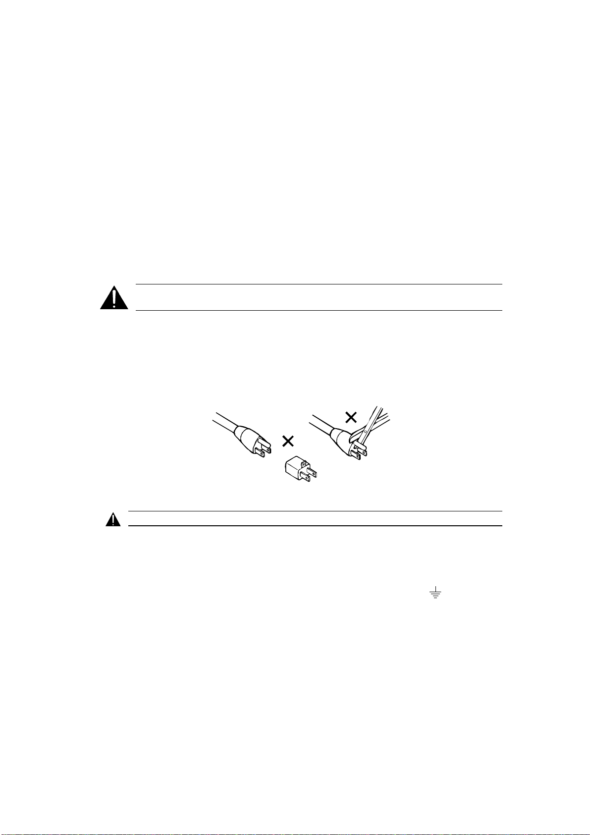
The ground terminal of the power plug is connected directly to the chassis of the unit. For
conti nued protection agai nst electr ic shock , a thr ee- p in, correctly wir ed and eart hed power ou tlet
must be used. Do not use a ground-lifting adapter and never cut the ground pin on the three-prong
plug.
: Check that the correct fuse has been installed. To reduce the risk of fire, replace the
FUSE - 2 Amp, time-lag (T2A), 20 mm long, 250 Volt
Dolby part no. 56027
UK
WARNING
As the colours of the cores in the mains lead may not correspond with the coloured markings
iden tifying th e term ina ls in your pl u g , pr oceed as follows:
: THIS APPARATUS MUST BE EARTHED.
• The core that is coloured green and yellow must be connected to the terminal in
the plug that is marked with the letter E or by the earth symbol
green or g reen and yell ow.
• The core that is coloured blue must be connected to the terminal that is marked
with the letter N or coloured black.
• The core that is coloured brown must be connected to the terminal that is marked
with the letter L or coloured red.
or coloured
IEC
This unit complies with the EMC r equir ement s of EN50081-1 and EN 50082-1 when insta l led in
an E2 environment in accordance with this manual.
Page 15

1-6
IMPORTANT SAFETY NOTICE
This unit complies w ith th e safety standard IEC65. To ensure safe op eration and to guard
against potential shock hazard or risk of fire, the following must be observed:
o If the unit has a volta ge s e lector, ensure that it is s e t to the correct mains voltage for your supply. If there is n o voltage
selector, en sure that your supply is in the correct range for the input requirement of the unit
oEnsure fuses fitted are the correct rating and type as marked on the unit.
o The unit must be earthed by connecting to a correctly wired and earthed power outlet.
oThe pow er cord supplied with th is unit must be wired as follows:
Live—Brown Neutral—Blue Earth—Green/Yellow
IMPORTANT – NOTE DE SECURITE
Ce materiel est conforme à la norme IEC65. Pour vous assurer d'un fonctionnement sans danger et de prévenir
tout choc électrique ou tout risque d'incendie, veillez à observer les recommandations suivantes.
o Le selecteur de tension doit être placé sur la valeur correspondante à votre alimentation réseau.
o Les fusibles doivent correspondre à la valeur indiquée sur le materiel.
o Le materiel doit être correctement relié à la terre.
o Le cordon secteur livré avec le materiel doit être cablé de la manière suivante:
Phase—Brun Neutre—Bleu Terre—Vert/Jaune
WICHTIGER SICHERHEITSHINWE IS
Dieses Gerät entspricht der Sicherheitsnorm IEC65. Für das sichere Funktionieren des Gerätes und zur
Unfallverhütung (elektrischer Schlag, Feuer) sind die folgenden Regeln unbedingt einzuhalten:
o Der Spannungswähler muß auf Ihre Netzspannung ein gestellt se in .
o Die Sicherungen müssen in Typ und Stromwert mit den Angaben auf dem Gerät übereinstimmen.
o Die Erdung des Gerätes muß über eine geerdete Steckdose gewährleistet sein.
o Das mitgeliefe rte Netzkabel muß wie folgt verdrahtet w erden:
Phase—braun Nulleiter—blau Erde—grün/gelb
NORME DI SICUREZZA – IMPORTANTE
Questa apparecchiatura è stata costruita in accordo alle norme di sicurezza IEC 65. Per una perfetta
sicurezza ed al fine di evitare eventuali rischi di scossa êlettrica o d'incendio vanno osservate le
seguenti misure di sicurezza:
o Assicurarsi che il selettore di camb io tensione s ia po sizionato sul valore corretto.
o Assicurarsi che la portata ed il tipo d i fusibili siano quelli pres critti dalla casa costruttrice.
o L'apparecchiatura deve avere un collegamento di messa a terra ben eseguito; anche la connessione rete deve
avere un collegamento a terra.
o Il cavo di alimentazione a corredo dell'apparecchiatura deve essere collegato come segue:
Filo tensione—Marrone Neutro—Blu Massa—Verde/Giallo
AVISO IMPORTANTE DE SEGURIDAD
Esta unidad cumple con la norma de seguridad IEC65. Para asegurarse un funcionamiento
seguro y prevenir cualquier posible peligro de descarga o riesgo de incendio, se han de observar
las siguientes precauciones:
o Asegúrese que el selector de tensión esté ajustado a la tensión correcta para su alimentación.
o Asegúrese q ue lo s fusibles c o lo cados son de l tip o y valor correctos, tal com o se marca en la unidad.
o La unidad debe ser puesta a tierra, conectándola a un conector de red correctamente cableado y puesto a tierra.
o El cable de red suministrado con esta unidad, debe ser cableado como sigue:
Vivo—Marrón Neutro—Azul Tierra—Verde/Amarillo
VIKTIGA SÄKERHETSÅTGÄRDER!
Denna enhet uppfyller säkerhetsstandard IEC65. För att garantera säkerheten och gardera mot
eventuell elcho ck eller brandrisk, måste följande observeras:
o Kontrollera att spänningsväljaren är inställd på korrekt nätspänning.
o Konrollera att säkringarna är av rätt typ och för rätt strömstyrka så som anvisningarna på enheten föreskriver.
o Enheten måste vara jordad genom anslutning till ett korrekt kopplat och jordat el-uttag.
o El-sladden som medföljer denna enhet måste kopplas enligt foljande:
Fas—Brun Neutral—Blå Jord—Grön/Gul
BELANGRIJK VEILIGHEIDS-VOORSCHRIFT:
Deze unit voldoet aan de IEC65 veiligheids-standaards. Voor een ve ilig gebruik en om het gevaar van electris che
schokken en het risico van brand te vermijden, dienen de volgende regels in acht te worden genomen:
o Controleer of de spanningscaroussel op het juiste Voltage staat.
o Gebruik alleen zekeringen van de aangegeven typen en waarden.
o Aansluiting van de unit alleen aan een geaarde wandcontactdoos.
o De netkabel die met de unit wordt geleverd, moet als volgt worden aangesloten:
Fase—Bruin Nul—Blauw Aarde—Groen/Geel
GB
F
D
I
E
S
NL
Page 16

SECTION 2
EQUIPMENT REQUIRED
The following equipment is required for proper installation and alignment of the
CP500 Digital Cinema Processor.
• Dual-trace oscillos cop e w ith X-Y fac ilities (minimum bandw idth 20 MHz, 50
MHz recommended).
• Ca libr ate d mic rophone ( preferab ly multiple micr ophon es and a multip lexer ).
• Sound pressure lev el me ter with slow time-con stant an d C we ighting scale .
• Voltmeter for measuring the exciter lamp power supply.
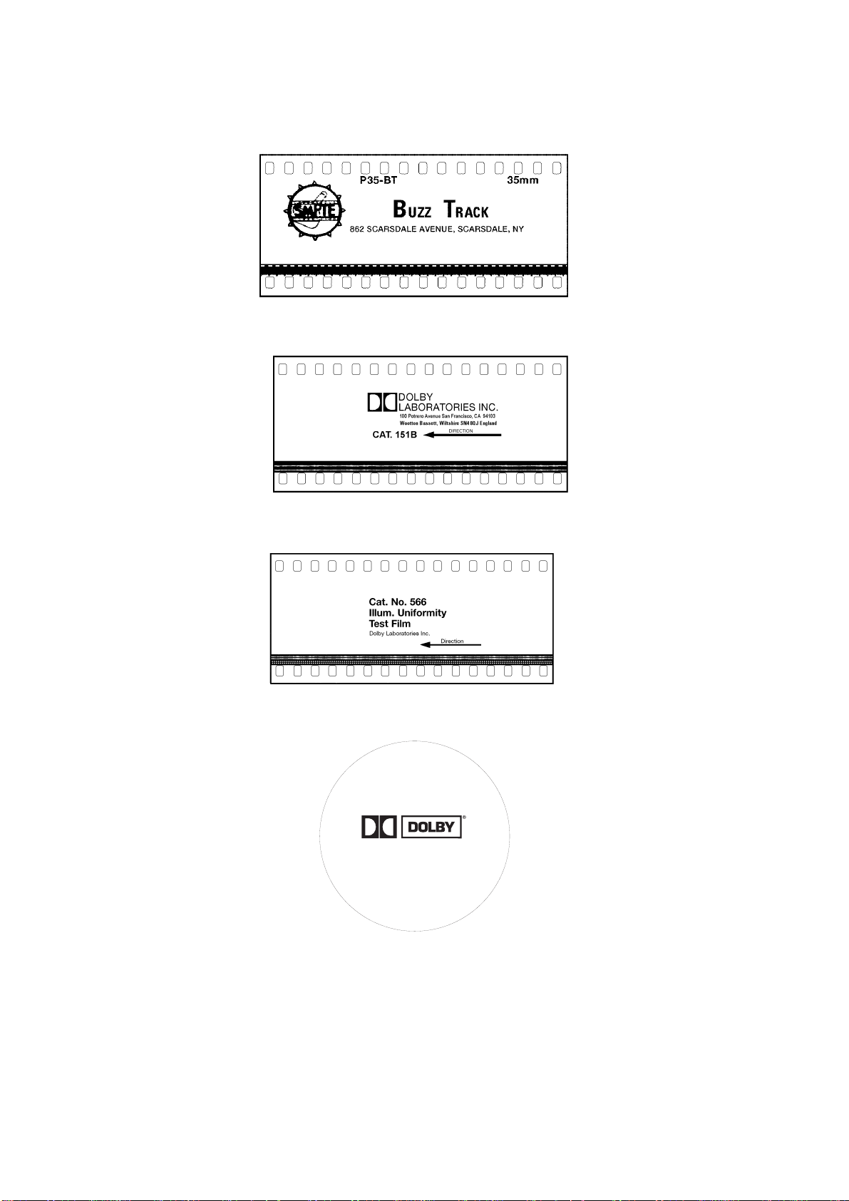
• Test Films, a vailable from Dolby Lab ora tories or equipment deale rs (Figures 2-1
through 2-7). We r ec ommend that you mak e loop s of these test films, lon g
enoug h to go th rough the entire projector film pa th so that a zimu th an d la teral
film pos ition adju stments can be made accurat ely.
Figure 2 - 1.
Figure 2 - 2.
Dolby Tone – Cat. No. 69T.
Pink Noise – Cat. No. 69P.
Figure 2 - 3.
1kHz, Crosstalk/Cell Alignment – Cat. No. 97.
Page 17
2-2
Figure 2 - 5.
Figure 2 - 6.
Figure 2 - 4.
SMPTE Buzz Track.
Stereo Optical Surround Level – Cat. No. 151B.
Illumination Uniformi t y – Cat. No. 566.
JIFFY
TEST FILM
Cat. No. 251 SR•D—A subjective film for testing theatre sound
Figure 2 - 7.
“Jiffy” Test Fi l m – Cat. No. 251 SR/Digital.
Additional te st films used dur in g Dolby D igita l system installation:
•••• Cat. No. 1010 Sync Test
•••• Cat. No. 1011 Channel ID
•••• Cat. No. 1012 Dolby Level
RECORDED IN
Running Time:
Picture format:
Dolby, the Double-D symbol and Dolby Stereo are trademarks
6 minutes
1.85:1 widescreen or
2.35:1 anamorphic
Sound formats:
10
05
digital
analog
Dolby Laboratories Inc. • 100 Potrero Avenue
San Francisco, CA 94103-4813
Telephone 415-558-0200 • Facsimile 415-863-1373
of Dolby Laboratories Licensing Corporation
S96/10117/11146
Page 18

INSTALLATION AND JUMPERS
Do NOT connect the CP500 to mains power until all connections have been made
and all jumpers have been checked or set.
If air-conditioning noise is audible in the theater, arrange for lubrication of the
motor, fan bearings, adjustment of belts and drives, and cleaning of filters t o reduce
the ambient noise to a minimum. If the air-conditioning cannot be repaired switch it
off while the CP500 is being aligned.
3.1 Replacing an Existing Sound System
If the CP500 replaces an existing cinema sound system, play a typical film before
yo u remov e the old system so you w ill hav e a ben chmar k for compa ris on to the new
system. It can also serve as a check of the positioning of the exciter lamp, the
focusing of the soundtr ack lens, and the condition of the solar cell.
SECTION 3
3.1.1 Before playing the film:
• Verify that the existing power amplifiers are in good working order.
• Verify that the existing speakers are in good wo r king order, and that
there is no loose or missing hardware, stru ctural parts, or damaged
drivers in the enclosures.
• Verify that all wiring is present and properly connected and that
crosso vers are operating and are correctly adjusted.
• Check the polarity of the speaker connections.
• Verify that there are adequate earth (gr ound) connections.
• Verify that radio interference problems are adequately resolved.
3.1.2 While playing the film:
While you run the film, listen ca refully in va rious parts of th e theater for audio
system problems:
• Hum.
• Noise, clicks, pops.
• Distorted so und.
• Poor to nal balance ( lack of high-frequency or bass content).
These problems must be resolved before you can proceed with the new installation.
3.1.3 Disconnect the old system
• Disconnect power from the existing cinema sound equipment.
• Disconnect all cabling from the existing sound processor. Leave the
cables connected to the power amplifiers, booth monitor, etc.
Page 19
3.2 Mount the CP500
To avoid heat problems, do not mount t he Do lby CP500 immedia tely a bove or
below the power amplifiers. Locate the power amplifiers away from the CP500 to
avoid hum pickup problems. Always leave a 1U (43 mm, 1.75") space above and
below the CP500 t o provide adequate ventilation. Install an air guide or baffle to
deflect hot air from equipment below the CP500.
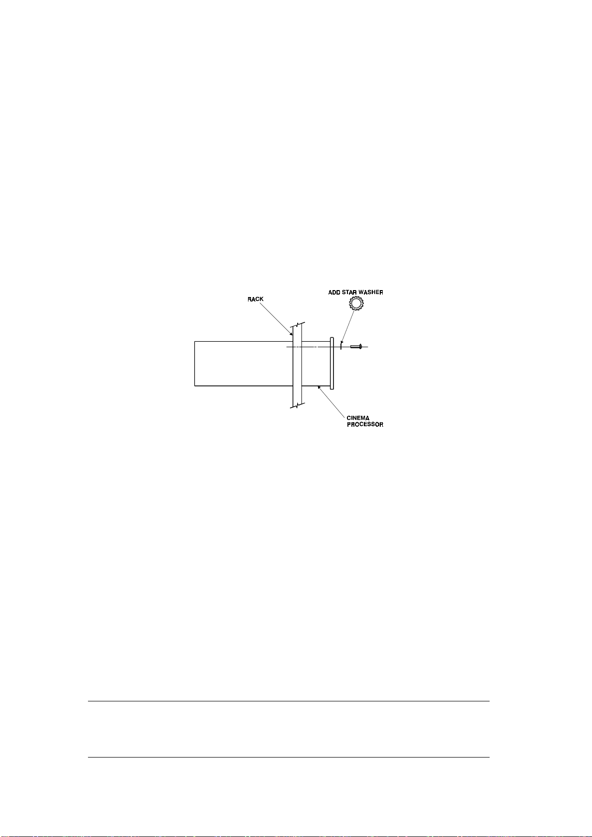
To ensure go od gro und contact, install star washers on all or at least one rack
mounting screw per piece of equipment (Figure 3-1). Th is will als o aid in the
prevention of electrical noise problems.
3-2
Figure 3 - 1.
Install star washers to rack mounting screws
Proper shielding and termination of cables and cable assemblies are also very
important. Be su re to follow the meth ods shown in th e w iring d iag rams.
If you a re ins talling a Dolby Cat. No. 700 Digital Soundtrack Reader, refer to its
installation man ua l for mou nting an d a lignment.
3.3 Connect the CP500
Refer to the approp r iate fold-out page ( at the end of this section) showing
connections to the various CP500 model configurations.
Make output signal connections by inserting stripped and tinned leads into the
supplied cable connectors and tightening each lead in place by means of the integral
set screw. The cable connectors are then plugged into place at the cor r esponding
locations shown on the fold-out wiring diagram. Shields must be connected as
shown in the fold out page to avoid radio frequency interference.
NOTE
:
Follow all local codes and regulations covering electrical wiring. It is recommended that conduit be
used for wiring runs.
.
Green plastic connector shells have been included in your installation kit for use in countries which are
governed by the E MC directi ves.
The shells
must
be used as noted on the fold-out pages.
Page 20

3-3
3.3.1 Connect Motor Start Relays
For two-pro jecto r installations, motor st ar t relays are required for projecto r
changeover. Digital data on the soundtrack is read in advance of the picture,
therefore an advanced changeover signal is required (see Appendix C). Projector
motor st ar t contact closures provide this signal to the CP500. Isolat e d contact
closures from mechanical or opto - isolated relays wired across projector motors
must be used. Refer to the Installat i o n Wi ri n g Power and Control diagram at the
end of this section.
Signal lev els :
Motor St ar t Less than 1 Vdc with respect to signal ground.
Moto r Off: Greater than 3.5Vdc, less than 18Vdc.
Re fer to the unit c onnections fo ld-out diagram for d etails ( located at the end of this
manual). For single projector installations, a prewire connector is supplied.
(Models CP500-D, and - 70)
3.3.2 Connect Remote Controls
The CP500 is equipped for use with three types of remote controls: the Cat. No .
689, and Cat. No. 734, which are offered by Dolby Laborator ies, and an auditorium
fader, which can be made from parts purchased at an any electronics store.
The Cat. No. 689 CP500 Remote Control duplicates the front panel format
selection, fader, and mute controls of the CP500.
The Cat. No. 734 CP500 Remote Fader consists of a shaft encoder with LEDs to
indicate the fader setting.
The auditorium fader is a 100k linear pot wired as a variable resistor, with
minimum resistan ce corresponding to fade r 10.
Details on how to connect any of these remotes t o the CP500 are shown in the
Installa t i o n Wi ri n g Power and Control drawing located at t he end of this section.
Page 21
3-4
3.3. 3 Connec t ion of Sola r Cell Boa rds
In contrast to t r aditional solar cells, the Cat. No . 655 and other solar cell circuit
boards used by several projector manufacturers are act ive devices with their own
power supply. Some care needs to be given to the wiring between the board and the
CP500 in order t o avoid grounding problems and to provide immunity to RF
interference. In principle, this means separating the audio ground connections and
the RF shielding screen connections.
The 0V point (audio ground) must be connected from the basement reader card to
the CP500 by a separate wire (or wires) along with the audio signal wires. The
cable shield (screen) must be kept separate from the audio ground connections. It
must be connected only to the chassis or enclosure of the equipment at each end.
Th e following diagrams ( Figures 3-2 and 3-3) sho w two connectors on the board.
The three pin connector, J1 is used for the power supply. The signal output
connector J2 pr ovides six output pins; two each for the "balanced" left and right cell
outputs, and two 0V audio gro und connections.
NOTE:
The following tables show the Right channel appearing on pins 1, 2, and 3 of the 6-pin connector J2.
The physical orientation of the board mounting in the projector and the orientation of the connector body
mounting on the board affect which channel appears on which pins of the connector.
allocations for the channels will vary depending on mounting arrangements of the board and
connector
. The J2 connector pin solder hole with a square outline is pin 1.
J2 Pin Number Signal
1
2 Signal Ground 2 Signal Ground
3
4
5 Signal Ground 5 Signal Ground
6
Right
Right –
Left
+
Left
–
+
OR:
J2 Pin Number Signal
1
3
4
6
Be aware that pin
Left
-
Left
+
Right
-
Right
+
There must be a connection between the ground pins at the Cat. No . 655 solar cell
circuit board and the audio common in the CP500. This connection must
not
use
the shield of the optical input cable, otherwise RF energy can be imposed on the
CP500 ground system.
Pin numbers 6 and 9 of each 9-pin D connector ("Pro jecto r ") on the CP500 allow
these connections to be made. The wire that connects either of these pins to t he
Cat. No. 655 audio ground should pass inside the same shield as the optical input
cables and not connect with the shield at any point.
Page 22
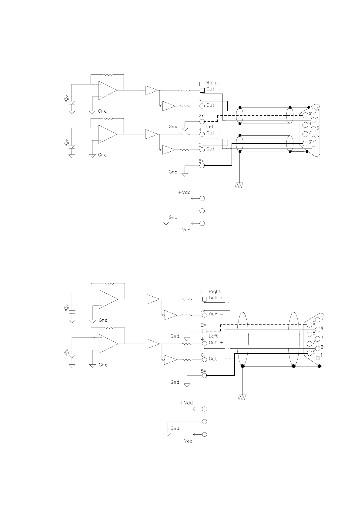
* Ground Wire on J2 Pin 2 is Optional
* Ground Wire on J2 Pin 5 is Required
3-5
J2
Cinema Processor
Chassis Ground
J1
Figure 3 - 2.
Wi r i ng using two 3-wire shielded (screened) cables.
* Ground Wire on J2 Pin 2 is Optional
* Ground Wire on J2 Pin 5 is Required
J2
Cinema Processor
Chassis Ground
J1
Figure 3 - 3.
Wi r i ng using one 5 or 6-wire shielded (screened) cable.
Page 23
3.4 Check and Set Jumpers
Next, check the following jumpers located on each circuit card. T he factory settings
for each jumper are shown in [brackets].
3-6
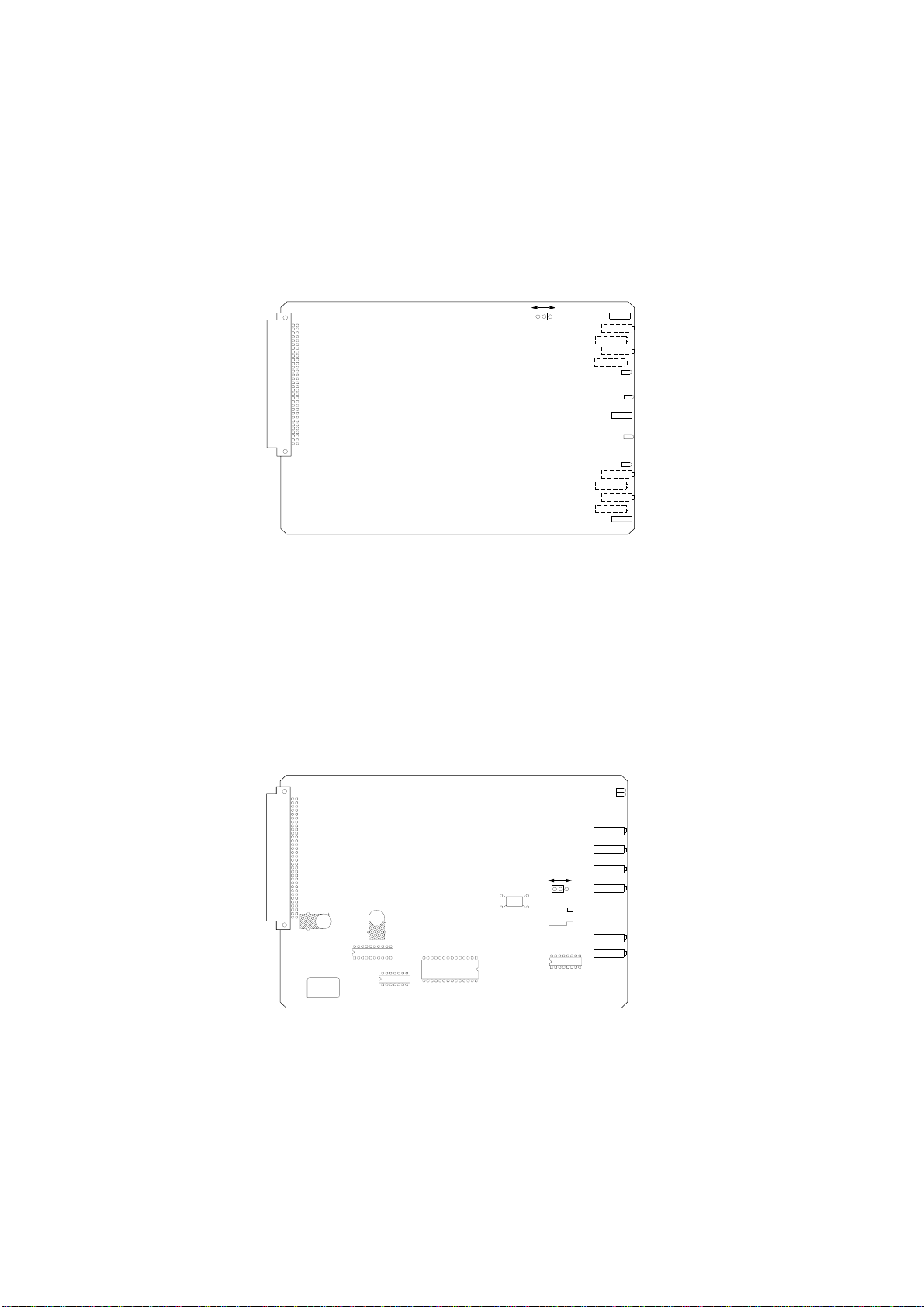
Cat. No. 661 Optical Pre-amplifier Card
POWER-UP PROJECTOR
SELECT JUMPER
CAT.NO. 661
Figure 3 - 4.
(Analog Soundtracks)
PROJECTOR 1
J2
Cat. No. 661.
J2 Power-up Projector Select (Wake-up state) [P 1]
Th is ju mpe r determine s which projector is s ele cte d w hen pow er is firs t
applied to the CP500. When J2 is set to “P1”, Projector 1 is selected at
power up. When J2 is set to “P2”, Projector 2 is selected at power up. The
jumper is set to "P 1" at the facto r y.
PROJECTOR 2
DS503
PROJ 1
SIG1
DS501
GND
SIG 2
PROJ 2
Cat. No. 681 Analog Switch Card
PHANTOM MIC POWER
FOR EQ MIC
J3
C63
C64
IC9
IC6
IC8
IC7
Figure 3 - 5.
CAT.NO. 681
Cat. No. 681.
L1100
J3 Equalization Microphone Phantom Power [OFF]
This jumper enables a phantom power sour ce for theater equalization
microphones which require phantom power t o operate. When the jumper is
set to the “ON” position, phantom power (15V) is supplied to the EQ
microphone jack and the rear panel microphone connector.
DS100
DS200
CW
RV101
NONSYNC1 L
CW
RV201
R135
NONSYNC1 R
CW
RV100
R235
NONSYNC2 L
ONOFF
CW
RV200
NONSYNC2 R
J2
CW
RV1100
EQ MIC
CW
RV2100
SIG MIC
Page 24
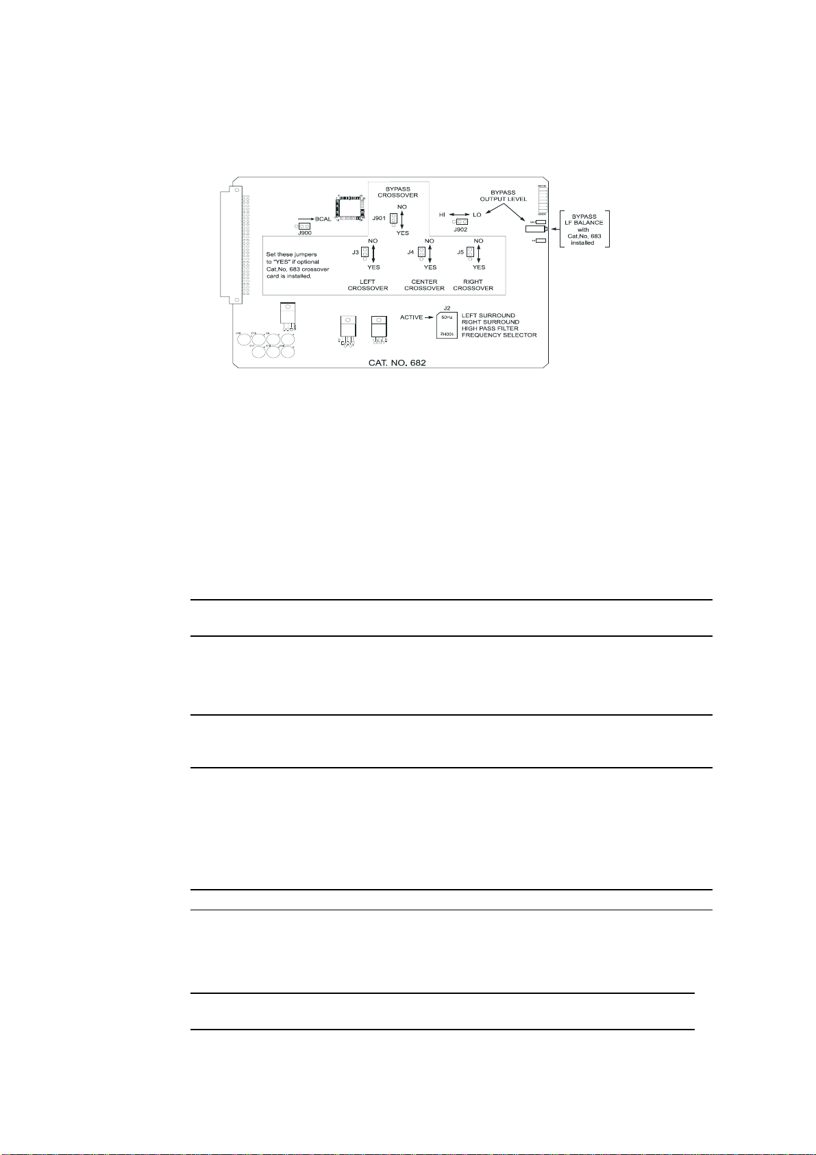
Cat. No. 682 Analog Output Card
3-7
Figure 3 - 6.
Crossover Select Jumpers [NO]
J3 Left Channel
J4 Center Channel
J5 Right Channel
J901 Bypass Audio Channel
These jumpers rout e the designated signals through an optional Cat. No. 683
crosso ver car d. If the Cat. No. 683 car d is installed, these jumpers should be
set to the “YES” position. If the optional Cat. No. 683 is not present, these
jumpers should be set to the “NO” position. The jumpers are set to the “NO”
position at the factor y.
NOTE
:
If bypass audio is routed to the optional Cat. No. 683 crossover card, the bypass portion of the
crossover circuitry must be functioning in order to produce a bypass audio output.
J900 Bypass Calibration
Th is ju mpe r inse rts a c alibrated pin k noise signal in to th e bypass system for
level a nd (optiona l) crossover a djustments . The calibra tion signal is enable d
when the jumper is in the “BCAL” position and is disabled otherwise.
NOTE
: It is important to move the jumper to the disabled position after calibration is complete so that
the bypass signal path remains completely isolated from any possible erroneous signals in the signal
path.
Cat. No. 682.
J902 Bypass Channel Output Level Select [LO]
This jumper, along with the bypass gain adjustment pot ent iometer (RV901),
adjusts the level of the bypass channel. The jumper provides a “coarse” gain
se tting and the potentiometer pr ovides a “fin e” ga in adju stment. The “HI”
jumper position can be used to produce a higher output level range on the
bypass channel. This ju mpe r is factor y set to the “ LO” p osition.
NOTE
:
If Cat. No. 683 Crossover card is installed, t he preferred se tting for this jumper is HI.
J2 L and R Surround High-Pass Filter Frequency Select [50Hz]
This header sets filter circuits to t he indicated high-pass frequency. Signals
below this frequency are attenuated in order t o prevent distort ion or damage to
surround speakers t hat ar e unable to handle extreme low frequency energy.
NOTE
:
The function of the Bypass Output Level control changes to Bypass Low Frequency
Balance Control if a Cat No. 683 Crossover Card is installed.
Page 25
3-8
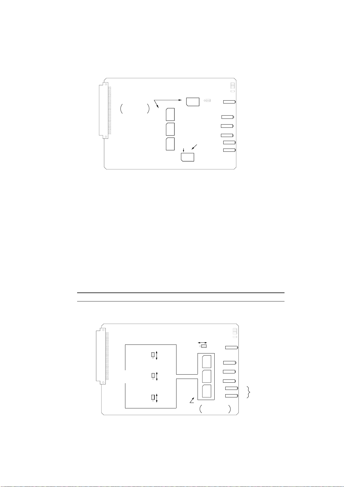
Cat. No. 683 Crossover Card (Optional)
500 Hz500 Hz500 Hz
BYPASS
RN600
LEFT SURROUND
RIGHT SURROUND
CROSSOVER FREQ
ACTIVE
50 Hz
RN400
500 Hz
BASS SPEAKER
SELECTOR
100 Hz
CROSSOVER FREQUENCY
SETTING HEADERS
Freq setting for large
horn is shown.
LEFT
CENTER
RIGHT
RN102RN202RN302
CAT. NO. 683
Figure 3 - 7.
Cat. No. 683 – Crossover Frequency Setting Headers.
Crossover Frequency Setting Headers- Screen Channels
RN102 Left Channel
RN202 Center Channel
RN302 Right Channel
RN600 Bypass
These headers select the desired crossover frequency. For large horns, the
correct setting is usually 500 Hz. For small horns, 800 Hz is usually
correct. Check the loudspeaker manufacturer’s specifications for details.
Be sure to select the same Bypass crosso ver frequency header as the
screen channels use. The headers are shipped with each card.
NOTE
: Custom settings are possible. See
LOW
FREQUENCY
DELAY
CAT. NO. 683
Figure 3 - 8.
Cat. No. 683 – Low Frequency Time Delay Enable Jumpers
J100
J200
J300
DELAY
NO DELAY
DELAY
NO DELAY
DELAY
NO DELAY
Appendix B, Cat. No. 683
BYPASS CHANNEL
HIGH FREQUENCY GAIN
J600
LEFT
CENTER
RIGHT
DELAY SETTING HEADERS
LOHI
RN101RN201RN301
1.9 mSEC 1.9 mSEC 1.9 mSEC
Delay setting for large
horn is shown.
.
BYPASS LEVEL
L
HF BALANCE
HF BALANCE
C
R
HF BALANCE
L
S
LF BALANCE
R
S
Page 26

3-9
Low Frequency Time Delay Enable Jumpers [DELAY]
J100 Left Channel
J200 Center Channel
J300 Right Channel
These jumpers allow the low frequency port ion of the designated channels
to be delayed when the jumper is placed in the “DELAY” position. This
compensates for the time offset caused by high frequency drivers being
behind the low frequency drivers in contemporary stage speakers. With the
jumper in the "DELAY" position, sound produced by the low frequency
speakers is delayed to cause the low and high frequency energy to reach
t he listen er at the same time. T here is no low frequency delay when the
jumper is set to “NO DELAY”. The factory sett ing is “DELAY”.
Low Frequency Time Delay Setting Headers
RN101 Left Channel
RN201 Center Channel
RN301 Right Channel
For large h orns, the correct d ela y setting is u su ally 1.9 ms . For s mall
horns, 0.8 ms is usually correct. The headers are shipped with each card.
NOTE
: Custom settings are possible. See
Appendix B, Cat. No. 683
.
RN400 L and R Surround Low-Pass Filter Frequency Select [50Hz]
This header sets filter circuits to t he indicated low-pass frequency. Signals
below this frequency are sent to the surround channel low frequency
drivers. Both the Cat. No. 682 Output card and t he Cat. No. 683 have
reversible filter headers for the surround channels. Ensure that t he headers
on both cards are set to the same frequency, chosen to suit the low
freq ue ncy h andling cap ability of the surround sp ea ke rs in use. If you ha ve
surro u nd bass drivers, it is probably best t o set bo th headers to
100 Hz in order to improve the low frequency power handling abilit y of
the surround channel. The factory sett ing is 50Hz.
J600 Bypass Channel HF Output Level Range [LO]
This jumper selects between two gain ranges for t he bypass channel high
frequency output. The “HI” setting has approximately 12 dB higher
output level than the “LO” setting. The factory setting is “LO”.
Page 27

3-10
3.5 Install Ci rcuit Cards - Card Descriptions
If they are not already installed in the CP500 unit, install all of the cards for your
system as shown below for each CP500 version. Note that the noise reduction
modules (Cat. No . 222SR-A) are shipped uninstalled. Th is is to prev ent da mag e
during shipment due to their weight. Sho u ld it ever be necessary to ship the CP500
again, be sure to remove these from the unit and pack them separately.
NOTE
: Cat. No. 222SR-A modules are primarily intended for playback of 35mm photographic soundtracks,
and have headroom capabilities based on that medium. As a result, use of Cat. No. 222SR-A modules are not
recommended for playback of 35 mm magnetic print-masters or SR encoded 70mm magnetic film. Contact
Dolby Laboratories for further information.
Model CP500-D
Cat. No. 222SR/A Module
Provides two channels of Dolby A-type noise reduction and Dolby SR processing.
Cat. No. 661 Optical Preamplifier Card *
Must be functioning for bypass operation
*
Amplifies the outputs of the analog soundtrack solar cells in the selected projector.
Projecto r select logic.
Provide s slit loss equalization.
Cat. No. 681 Input Switch Card
Stereo analog multiplexer for selecting signal to be fed to noise reduction cards.
Audio sample rate clock.
Cat. No. 675A Digital Signal Processing Cards (2)
Matrix decoder for Dolby Pro-Logic.
No n-sync processing.
Signal generation and signal analysis functions.
Twenty-seven band 1/3 octave equalization for L, C, R channels.
Nine band octave equa lizatio n for L a nd R su rround channels.
Equalization for subwoofer channel.
Cat. No. 685 6-Channel Analog to Digital Converter Card
Used for external 6-channel analog inputs (optional).
Cat. No. 662 6-Channel Digital to Analog Converter and Voltage
Controlled Amplifier Card
Converts digital data to analog audio and includes the main fader voltage controlled
amplifier.
Cat. No. 682 Analog Output Card *
Must be functioning for bypass operation
*
Switches and routes output channels.
Contains treble and bass control circuits.
Generates hearing impaired output and mid-surround output.
Contains bypass power regulator and output amplifier.
Cat. No. 684 System Controller Card
Mu st be present for lev el c on trol in bypass mode. Bypass will fu n ction at a fix ed
level if this car d is not pre sent or ope ra tional.
Page 28

3-11
Contains Microprocessor.
Controls front pa nel displa y and controls.
Contains interface for remotes and automation equipment.
Cat. No. 683 Crossover Card (Optional)
Provides active high- an d low -pass filters on L , C, and R signals fo r bi-amplified
installa tion s.
Provides low frequency surround channel outputs.
Provides low freque n cy d ela y for time alignment of L, C, and R low fr eq ue ncy
drivers.
Contains bypa s s crossover and must be p rese nt fo r bypass operatio n in bi-a mplified
systems.
Dolby Digital Soundtrack Processing System
Cat. No. 670 Video Front-end Card
Digitizes the video data received from the film sou ndtrack r ea de r.
Cat. No. 671 DSP Cards (2)
Processes the digitized video data and extract s the AC-3 bitstr eam.
Cat. No. 673 System Services Card
Contains the operat ing software.
Cat. No. 675A Digital Signal Processing Card
This additional Cat. No. 675A provides Dolby AC3 decoding.
Cat. No. 680 Bit Rate Converter Card
Converts PCM audio from the variable projector r ate clock to a stable PCM
audio sample rate.
Model CP500-D/300
Contains the same boards as the CP500-D above, except Cat. No . 300 modules are
used in place of the Cat. No. 222SR/A modules. A Cat. No. 668 Adapter Card is
required. Used primarily in preview theaters and studios.
Model CP500-SR
Contains the same boards as the CP500-D above except without the Dolby Digital
soundtrack pr ocessing system cards.
Model CP500-70
Contains the same boards as the CP500-D, and additionally:
Cat. No. 222A Modules (2)
Provides four additional channels of Dolby A-type noise reduction bringing the total
number of noise reduced channels to six.
Cat. No. 669 Adapter Card
Us ed for installing th e tw o Cat. No. 222A cards above.
Cat. No. 685 6-Channel Analog to Digital Converter Card
Used for external 6-channel analog inputs.
Page 29

3.6 Bypass Power Wiring
For emergency operation, t he CP500 co mes equipped with an independent external
mains power module. If the main power supply or processor circuitry fails, the unit
will automatic ally switc h to byp as s operation , allowing the show to contin ue with
limit ed sound processing functions. T he unit can also be switched manually to
bypass operation by pu s hing a butt on loc ated inside the front panel and labeled
POWER/BYPASS.
In some cou ntr ies the pr imary cable for the modu le ma y n ot hav e a mains plug
fitted. These unterminated leads must be as follows:
Brown wire -- Live or hot Blue wire -- Neutral
NOTE
:
If you are uncertain about the wiring of your mains outlet do not use it. Consult a qualified
electrician.
3-12
For safety reasons, the bypass power module contains an internal fuse.
mains power until the output wires have been connected to the CP500. Otherwise, shorted secondary wires
will blow the fuse.
DO NOT
connect the module to AC
Install the ferrite clamp on the bypass power supply cable where it connects to the
back of the CP500. Open the clip and wrap the bypass power supply wire around
one side of the ferrite three times so that t he loo ps lie inside the ferrite channel.
Close the clip until it snaps firmly closed. Make sure that the bypass power supply
cable is not pinched between the halves of the ferrite clamp.
Page 30
3.7 Power On
Connect the bypass power module to the CP500 and plug it into AC mains. The
unit is shipped with the POWER/BYPASS switch set to BYPASS. The front panel
BYPASS LED should light.
Open the front panel and confirm that one of the Pro jecto r S elect LEDs is on.
Projector 1 or Projecto r 2 is selected by Jumper J2 on the Cat. No. 661 (See
manual section 3.4).
Connect the main power cable. Then, push the Bypass/Power button to turn on the
CP500.
3-13
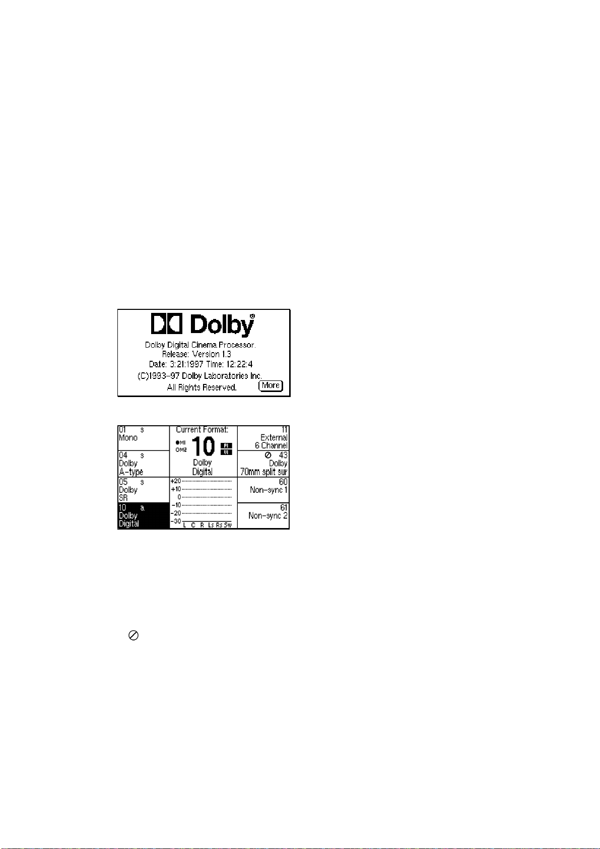
When power is first applied, the first
screen that appears displays the revision
level of t he so ftwa re. Next, a brief
"Loading System" message is displayed.
In a few seconds, the Current Forma t
screen appears. This is the normal screen
that t he projectionist or any other
operat or would see and the only screen
t h ey w ill n ee d to see for ordin ary
purposes.
Run quick checks to co nfirm that:
• Rotating the front panel knob changes the numbers displayed next to it.
• Pushing the MUTE button causes the MUTE LED to flash.
• Pushing any of the buttons on each side of the display causes the mute LED to
go off and the LED next to the bu tto n pushe d to go on (except buttons next to
" " on the display).
Page 31

3-14
3.7. 1 Hum a nd O t he r Noise Problems
If you hear undesirable hum from the speakers when you apply power to the CP500
and other pro jection room equipment, check the following list for possible causes.
1. Equipment grounding. All equipment including the CP500 is grounded to
the rack. To ensure goo d ground cont act, install a starwasher t o one
mounting screw per piece of equipment. Installation of star washers is
stro ngly recommended because electrical contact may not be achieved since
modern powder coat paints can be very tough.
2. Ground loops caused by audio signal wiring, especially to power amplifiers.
Be sure to check t he booth monitor installation.
3. Projector power wiring. All mains wiring sh ould be proper ly grou n ded.
4. Room lighting dimmer controls (SCR-TYPE).
5. Power amplifiers. Disconnect from the CP500 and ground the inputs to
determine if the powe r a mplifie rs are ca using h um problems.
6. S olar cell w iring. (An alog film sound forma t selec ted ). Ch ec k the sh ield
connections. Cell wiring should be placed away from mains and other
wiring. Cell wires must not be co nnected to t he frame of the projector.
7. Exciter lamp power supply. Check for ripple on the DC power supply
outputs. Some old exciter lamp power supplies and emergency supplies
provide AC to th e la mp. T he re su lting hum mak es them totally u n su itable
fo r a Dolby film soun d s ystem. Such excit er supplies must be replaced.
8. Projection room lighting/solar cells. Ambient lighting, especially
florescent tubes, can leak into the so lar cell area and cause hum.
Page 32

FRONT PANEL AND ALIGNMENT OVERVIEW
This section describes the CP500 LCD display and operation of the front panel
contro ls, along with of an overview of the general principles involved in the
alignment of Dolby cinema equipment. It is useful to develop an understanding of
why the CP500 is aligned as described in this manual. If the installer is already
familia r with the CP500 and these principles, or is in a hurry to complete the
installa tion , th is sec tion may b e read late r. Continue th e installation pr oce dure
beginning wit h Section 5.
4.1 The CP500 Front Panel
4.1.2 Soft Keys: SK1 to SK8
SECTION 4
(SK1)
(SK2)
(SK3)
(SK4)
(SK5)
(SK6)
(SK7)
(SK8)
The butto ns located on each side of the LCD display are sometimes called "soft
keys"(SK) . That is, t he y do not have a sing le fixed fu nc tio n but rather their function
is software contro lled and changes based on the current screen displayed. The
purpose o f each butto n is shown on the display and can change with each different
displayed screen.
4.1.3 Hard Keys
FORMATS
The single large and four small keys along the bottom of the display are the "hard
keys" . Their function is labeled on th e p anel. The la rge key on the left,
FORMATS, is used to return to the Format Selection (Current Formats) screen
from any other menu screen. This screen is displayed during normal day-to-day
operat ion of the CP500. If any other screen or menu is displayed, this butto n ret ur ns
t he display immedia tely to this "top" of the menu tr ee .
MENU
The MENU key is used as the first step in selecting all software functions and
menus except format selection. It selects or ret ur ns t he unit to the top menu.
Page 33

SOFT KEYS 1 - 8
Used to select the function shown
next to the switch in the front panel
display.
BYPASS INDICATOR
Indicates continuous red when unit is in
bypass mode.
MUTE ON INDICATOR
Flashes when mute is activated.
MAIN FADER/MULTI-FUNCTION CONTROL
Controls sound level and also is used for
data selection in menu operations.
(SK1)
(SK2)
(SK3)
(SK4)
FRONT PANEL DISPLAY
FRONT PANEL DISPLAY
Displays format and menu
screens.
FORMATS KEY
Used to switch to format
selection screen.
(SK5)
(SK6)
(SK7)
(SK8)
FADER LEVEL DISPLAY
Displays fader setting. Ranges from 0 to 10.
Normally set to 7.0 This display shows '- -'
when in data entry mode.
4-2
MUTE KEY
Mutes output to all channels when activated.
EXIT KEY
Used to select the previous menu.
OK KEY
Used during pop-up menu operations. Selects
option currently in pop-up window selection box.
Also stores currently displayed data.
CANCEL KEY
Used during pop-up menu operations. Cancels
pop-up menu operation and restores the
previous menu or data.
MENU KEY
Used to return to the top of the menu tree.
Page 34

4-3
CANCEL
Many of the screens used during set-up, alignment, or diagnostics contain a "PopUp" screen within the main screen. The CANCEL key is used to cancel the current
pop-up oper ation being performed and restore any data that was changed during the
pop-up screen operation.
OK
This key is used to accept and store the current set ting in a po p- up scr een.
EXIT
This key is used to signal completion of an adjustment procedure o r select the
previous screen.
4.1. 3 Ot he r Control s a nd Indicators
To t he right of the display is another window showing the selected fader level. As
with previous generations of Dolby cinema processors, a fader sett ing of "7.0" is the
nominal correct operating level. This setting matches the level used during the film's
production. As the main fa der (or front panel knob) is turned, the numbers on the
dis play will mov e fro m ze ro to te n. The mai n fader rotates continuously with no
end s tops . The number dis played w ill alw ays indica te the curr ent level setting.
Bypass
Mute On
The MUTE butto n is used to fade the sound down without disturbing the current
fader setting. A green LED, MUTE O N, located above the fader level display will
flash, indicating that the CP500 out puts are muted.
A BYPASS LED is located to t he left of the MUTE ON LED. As with other
Dolby cinema processors, the CP500 utilizes a separat e back-up po wer supply
which is used during emergency operation. If the CP500 is operating in bypass
mo de , this r ed LED will c ome on (not flash in g). If th ere shou ld be a failu re, th e
system can switch into bypass mode either temporarily or permanently. The
minimum electro nics required for a bypass output signal from the CP500 is:
• Functioning bypass power transformer (external module)
• Cat. No. 661 Optical Preamplifier card
• Cat. No. 682 Analog Output card
• Cat. No. 683 ( optional) Crossover card, if used in a bi-amplified
installation.
Page 35

A manual bypass push- but ton is loca ted inside t he fro nt p a nel on the r ight hand side
of the unit.
4.2 System Password
Many of the CP500 alig nment functions can be pro tected from unauthorized access
be using a system password (any fo ur numbers). A password can be stored after the
system is aligned in o r der to block any changes to the B-chain alig nment, level
settings, or time delays. Knowledge of this password would be required to enter
these CP500 menus. The CP500 is shipped with no system password. The number
stored in CP500 memory is "0000". This allows access to all alignment functions.
The following procedure should be used to set or change the system password.
4-4
Press the MENU key.
FORMATS
FORMATS
Menu Cancel OK
MENU
Menu Cancel OK
The Menu Selections sc reen will be
displayed.
Press Alignment (SK2).
Exit
The System Alignment screen will
appear. Press S e t System Passwo rd
(SK8).
Exit
NOTE
:
If a system password has already been
stored in memory, then the screen below will
appear.
Rotate the front panel knob to select the
digit you wish to set, then press and hold
soft-key SK4, "1234", while rotating the
front panel knob to set the desired
number. Repeat this process for any of
the four password digits you wish to set.
OK
Press the OK key to store the new
password.
Page 36

4.3 Aligning the B-Chain
The B-chain is defined as those system components from the fader through the
loudspeakers. In the CP500, available adjustments include equalization, level
contro l, and digital soundhead, analog, and digital surround delay settings.
Adjus table mute fa de -out time is also provide d.
It is not practical for the entire cinema industry to standardize on a single make and
model of lo udspeaker . I n any event, the different acoustical characteristics of
individual theaters would, to some extent, negate any such standardized speakers.
Electronic equalization of each loudspeaker system achieves consistent results in a
broad spectrum of environment s, and with a broad range of speakers. Accurat e
equalization requires the use of standardized acoustic measurement pr ocedures.
A pink no ise generator pr ovides a continuous random noise signal that covers the
total bandwidt h and is used to measure and adjust the response of the loudspeakers.
Th e use of r andom nois e e liminates the pr oblems inheren t with ton es (s tanding
wave patterns in the theaters) and enables the frequency response of the entire
system to be observed. Each channel can be measured and adjusted independently
of the other channels.
4-5
A calibrated microphone or a multi-microphone setup with multiplexer is placed in
the auditorium to receive the pink noise reproduced by the loudspeaker. The output
of the selected microphone is fed to a real time analyzer (RTA) circuit built into the
CP500 cinema processor, and equalization can be performed using t he CP500 front
panel display to show the audio spectrum received by the micr ophone(s). Pure pink
noise would yield a “flat” horizontal line on the RTA. Thus, the effect of
adjustments to the equalizers is quickly and easily seen.
One of the problems inherent in equalization is the nature o f the environment. In an
open space, a perfect loudspeaker, radiating a perfectly flat response in all
directions, placed in front of a perfectly flat microphone, pro ducing perfectly flat
response to soun ds arriving from all dire ctions, will d isp lay a pe rfectly flat r es ponse
on the RTA from pink noise. In an enclo sed space such as a t heat er , the results are
different. When the pink noise generator is first turned on, all of the sound that
init ially reaches t he microphone comes directly from the loudspeaker; the response
is fla t—for a few milliseconds. The n r eflecte d sound fr om th e w alls, ceilin g, floor,
seats, etc. star ts to ar r ive at the microphone together with the direct sound from the
loudspeaker. This indirect o r r eflected sound reinforces t he direct sound. T he
sys tem soon se ttles into an eq uilibrium con dition. As mu ch ener gy is bein g a bsorbed
at the w alls, ceilin g, etc. as is fed into the room. Since h igh and mid frequency
energy is absor bed when sound is reflected, the displayed respo nse appears to have
a risin g bass an d a falling treble ch aracteris tic. At fir st g lance, ro lling off th e bass
and boosting the high frequencies may appear to be the logical approach for a flat
steady-stat e r esponse, but such an arrangement works o nly on sustained sounds.
Dialogue contains short, impuls ive sounds and will yie ld a muc h-too-b right resu lt
Page 37

4-6
because there is no time for reverberation to build and add to t he o r iginal sound.
What is required is a curve that favors such impulsive “first arrival” so und and
implies th e same ge ntly fallin g response tha t is obs erve d whe n the outp ut of an id ea l
loudspeaker is measured with a perfect microphone in the theater.
The amount of reverberation varies with frequency and the higher the frequency the
mo re the treble will be absorbed rathe r than b eing r efle cte d. A typical r ever bera tion
curve in a theater rolls off at about 3 dB per o ctave above 2 kHz. This characteristic
is used to define the standard st eady-state response curve for all dubbing theaters in
which films with Dolb y soundtracks are mix ed and for all D olby processor-equipped
cinemas.
The size of the theater affects the reverberation time and, therefore, the
measurement of frequency response. After alignment to this standard curve, so me
slig ht adjustment of high frequency slope may be found necessary for extremely
large or small theaters. T he Treble Control can be used to reduce the out put on the
response curve by approximately 1 dB at 8 kHz for very large theaters; an increase
of 1 dB at 8 kHz may be in order for a very small theater. Any such adjustment
should be b ased on an evaluation b y ear of actua l known films rathe r th an as a r ule
of thumb.
Some loudspeakers used in theaters are far from ideal and require boosting of the
low- and high-frequency extremes in order t o produce an approximation of the
standard reference response curve. Bass and treble controls–centered on the
turnover po ints of typical loudspeakers–lift the ends of the spectrum without the
need for large a mounts of narrow -band boost from the third-oc tave EQ circuitry.
Th e final factor is masking of the scree n. Most films today are sh own in a w ide screen format. The masking curtains of the screen must be drawn back sufficiently
to clear the left and right speakers before any adjustments or measurements are
made. The treble horns should clear the screen frame and be mounted as close as
possible to the screen. Conventional black felt side masking can severely curtail high
frequency respo nse. Co nsequently, there would be severe losses if the left and right
lo ud sp eake rs wer e equalized w ith the masking open as for a 2.35:1 film, and then
t he masking wer e brou ght in for a 1.85:1 film, th us obscuring the outer speak er s.
To avoid this problem, some theaters have installed acoustically transparent
masking cloth, and others leave the masking open whenever they are showing a
1.8 5:1 film with a stereo soundtrack. M oving the speake rs to wa rds th e center of the
screen so as to clear heavy masking is not a good solution, since the stereo
separation would be degraded.
Repainted screens cannot be used for quality sound playback, since the perforations
which allow the high frequencies through the screen can become clogged with
paint.
Page 38

5.1 Check Theater Equipment
Thoroughly check the lo udspeaker s and po wer amplifiers for sources o f poor
performance:
• Check that the loudspeaker cables are in good condition and that they of a
suitable gauge for the impedance of the speakers and the length of the run.
• Rattles (a leak in the low frequency driver cabinet may appear to be a ratt le).
• Loose bolts or other hardware.
• Open drivers.
In systems with pairs of drivers – low frequency or high frequency – one
voice c oil of the pair may be ope n but the system will still fu nction .
Check the speakers with an ohmmeter. If one channel requires markedly
more equalization than the other o r if one speaker overloads at lower
levels than the other speakers, an open driver circuit could be the cause.
SECTION 5
B-CHAIN ALIGNMENT
• Missing drivers or other components.
• The settings of the crossovers to match the type of drivers in use and the
acoustics of the theat er .
The high fr eque ncy driver level control must be set fo r t he best possible
freq ue n cy response be fore you attempt any e qu aliz ation. This is also true if
the system uses active crossovers with bi- amp equipment.
• Phasing between the low frequency and high frequency drivers, and between the
channels.
• Aiming of spe ak ers.
Check that the speakers are correct ly aimed int o the auditorium, and that
they are not obst ructed by the screen frame, struts o r other o bstructions.
• Check that speakers are correctly connected; that the speaker on the left is
connected to the left power amplifier.
Amplifiers
• Distortion.
• Gross gain differences among amplifiers.
If one amplifier differs in performance fr om the others, it should be checked
and repaired, if necessary, before pro ceeding further. Input gain controls
should all be at the same setting.
Page 39

5-2
B-Chain Alignment
•
Blown fuses.
•
Good air movement through power amplifiers.
Air-conditioning
If air-conditioning noise is audible in the t heater , arrange for lubrication of the
motor and fan bearings, adjustment of belts and drives, and cleaning of filters to
reduce the ambient no ise to a minimum.
5.2 Preparing for Room Equalization
Using a Microphone Multiplexer with the CP500
If you are using a Dolby Cat. No. 580 Microphone Multiplexer system and need
instruction s on its use, tur n to
Section 9.2
.
5.2.1 Configure the Cat. No. 682 for use with the Optional Cat. No. 683 Electronic Crossover Card
Verify that the Cat. No. 682 jumpers J901, J3, J4, and J5 are set to the "YES"
position to enable the crossover features of the Cat. No. 683.
5.2.2 Screen Channels
The factory setting for t he Cat. No. 683 card has the Low Frequency Time Delay
Enable Jumpers set to DELAY. This indicates that jumpers J100, J200, and J300 of
the Cat. No . 683 car d allow the low frequency po r tion of the designated channels to
be delayed by 1.9 ms or 0.8 ms. The “DELAY” setting compensates for the time
offset caused by high fre quency driver s being behind the low frequency dr ivers in
contemporary stage speakers. S ound produced by the low frequency speakers is
delayed to cause t he low and high frequency energy to reach t he listener at the same
t ime. T here is no low fr eq ue ncy delay w hen the jump er is set to “ NO DELA Y” .
Board locations RN102, RN202, RN302, and RN600 select the desired crossover
frequency and locations RN101, RN201, and RN301 select the time delay. For
large horns, the correct set ting is usually 500 Hz and 1.9 ms. For small horns, 800
Hz and 0.8 ms is usually correct . Check t he loudspeaker manufacturer’s
specifications for details.
Page 40

5-3
B-Chain Alignment
Before you set out t o equalize the roo m, make sure you do the following:
1. Be sure to use the same Bypass crosso ver frequency setting header as the screen
channels use.
2. Carefully install t he co r r ect headers in the appropriate socket locations, making
sure to set the header cor r ectly.
3. Set all pow er amplifier gain pots to the maximum. Car efu lly ensure that on ly HF
outputs are ro uted to the HF horns to avo id damage from excessive low
frequency excursion of HF horn diaphragms.
4. Place microphones in the auditorium and connect the mikes and multiplexer (if
available) to t he CP500.
5. Set the fader leve l dis pla y to re ad “0”.
6. Enter the CP500 B-chain EQ screen and select Left channel.
7. Gradually turn the fader by moving the pointer to the fader slider on the EQ
screen. Verify by ear or spect r um analyzer or bot h t hat the low frequency driver
and HF horn are each producing only their appropriate halves of the spectrum.
8. Turn the fader up until a sat isfactory level is achieved in the auditorium.
9. Set all EQ con trols to flat.
10. Using the Left trimpot on the edge of the CN683, adjust the relative HF horn
o utp ut le vel so that the low frequ ency driver an d HF horn outp ut le vels match in
the oct aves just above and just below the crosso ver frequency. For example, if
the crossover frequency is set to 500 Hz, then the level from 250-500 Hz should
match that from 500-1,000 Hz.
11. Adjust the Right and Center channels, then proceed t o room equalization as
described in
Section 5.3
.
5.2.3 Surround Channel Bass Drivers (Optional )
Both the Cat. No. 682 Output card and the Cat. No. 683 card have reversible filter
headers labeled 50/100 Hz for the surround channels. Ensure that t he headers on
both cards are set to the same fr equency (usually t o suit the low frequency handling
capability of the surrou nd sp ea ke rs in use) . If you ha ve separate su rrou nd bass
drivers, it is probably best to set both headers to 100 Hz in order to improve the
lo w frequ ency powe r h andling ab ility of the surround channel.
Enter t he B-chain EQ screen and select Left Surround. Set the EQ to flat. Adjust
the Ls trimpot on the Cat. No. 683 so that the level in the room is reasonably equal
in the 40-100 Hz and 100-200 Hz regions on average. Now adjust the EQ contro ls
as usual.
Page 41

5.3 Room Equalization
Equalization is performed using a real-time analyzer built into the CP500. The
adjustment for the five full range channels involves two steps - coar se adjustment
and fine adjustment, using a 27-band equalizer for each of the screen channels (left,
center, and right), and a 9-band equalizer for the t wo surround channels (left
surround and right surround). Subwoofer channel equalization involves setting the
frequency, "Q", and level of "cut". The real-time analyzer screen displays a standard
response curve. The ideal setting is reached when the room response readings fall
on or very close to t his standard curve.
POWER AMPS
OFF
5-4
B-Chain Alignment
Set all the ga in controls on all po wer
amplifiers to a known repeatable setting.
The preferred setting for most
amplifier gain controls is maximum.
If a differ ent set ting is required in order
to optimize the noise performance of the
system, the contro ls should be locked in
position or marked clearly.
Position c alibra ted microphone s in th e
theater. Whenever possible, use multiple
microp h ones and a mu ltiple xer.
(Suggested microphone positions for use
with a multiplexer are show n in
9.2.
) For a single microphone, the
Section
recommende d p osition is shown in the
diagram – 2/3 of the way from the front
speakers to the rear – but o ff the axis of
the center speaker – 5 feet off the floor
level – and angled 45 degrees upward
towar d the screen.
Page 42

5-5
-
B-Chain Alignment
WARNING
: The following steps will cause the CP500 to output pink noise to the power
amplifiers. The CP500 is shipped with the output levels set to a minimum. If you are unsure of the
settings on your unit, turn off the power amplifiers before pressing the
Output Adjust
key. Then,
press the key and observe the front panel display; it will show the present output level adjustment
settings. With the settings at minimum, excessive loudness will usually not be a problem.
screen shows:
Format
Selection
screen shows:
Menu
Selection
screen shows:
System
Alignment
FMAS
Menu ancel
press:
press:
press:
Menu
key
Allignment
key
utput A ust
key
it
To perform a preliminary adjustment
of the output level:
Press the
Press
(A system password may be re quir ed at t his point.)
Choose
MENU
Alignment
key,
(SK2),
Output Adjust
(SK2).
PHANTOM MIC POWER
FOR EQ MIC
IC6
CAT. NO. 681
DS100
DS200
CW
RV101
NONSYNC1 L
CW
RV201
R135
NONSYNC1 R
CW
RV100
R235
NONSYNC2 L
CW
RV200
ONOFF
J3
L1100
NONSYNC2 R
J2
CW
RV1100
EQ MIC
CW
RV2100
SIG MIC
Ph antom pow er is optiona lly provided to
both connectors via a jumper on the Cat.
No. 681.
The spectrum analyzer, built into the
CP500, has automatic level control cover
ing a r ange of input le vels. How ever , if
you get an error message that r eads that
t he in put lev el is too low or too hig h, the
EQ mic trimpot on the Cat. No. 681
should be ad justed to ha ve th e le v el me ter
on the Cat. No. 222 show approximately
Dolby level for
85 dBC
pink no ise in the
auditorium. Th is will place t he signal in
the middle of the analyzer’s acceptable
level ran ge.
Page 43

5-6
B-Chain Alignment
LEFT SIGNAL PRESENT
RIGHT SIGNAL PRESENT
NONSYNC1 LEFT
NONSYNC1 RIGHT
NONSYNC2 LEFT
NONSYNC2 RIGHT
EQ MIC INPUT
EQ MIC
SIGNATURE MIC
CAT. NO. 681
Connect Cat. No . 580 Microphone
Multiplexer to th e mic rophone inpu t
connector on the rear panel, or if using
another typ e of multiplexer or s ingle
microphone, open the front door of the
CP500 and plug it into t he "EQ MIC
INPUT" connecto r on the Cat. No. 681
card. This is a balanced input connection
which is wired in par alle l with the re ar
panel connector . T he rear panel
connector can also be used with a single
micr ophone if a suitable cable or adapt or
is provided .
The left signal pr esence LED indicator
o n the top c ard ed ge should illuminate
indicat ing that signal is present.
If it is
not illuminated or is very dim, adjust
the "EQ Mic" con t rol to obtain
sufficient signal.
NOTE
:
If your microphone requires phantom
power, move jumper J3 on the Cat. No. 681
board to the ON position.
Pin k noise will now be routed to th e
center
channel output.
With a hand-held sound pressure level
meter, measu re the noise lev el in th e
room. Enter this re ading in the box displayed by rotating the front panel knob,
then press the OK key.
F
F
O
0
3
0
0
8
0
0
0
4
7
5
6
Th e c alibra tio n is retained in CP5 00
memory and can be used in future adjustments, ho w ever it is advisa ble to
recalibrate the system when re-arranging
micr ophones because the sound pressure
level w ill vary s lightly with micr ophon e
placement .
OK
Page 44

5-7
B-Chain Alignment
F
F
O
0
3
0
0
8
0
0
0
4
7
5
6
If the sound pressure level in the theater
is too low , a dialog box w ill ap pear on
the CP500 screen.
SIGNAL PRESENT
SIGNAL PRESENT
NONSYNC1 LEFT
NONSYNC1 RIGHT
NONSYNC2 LEFT
NONSYNC2 RIGHT
EQ MIC INPUT
RV1100
SIGNATURE MIC
CAT. NO. 681
EQ MIC
“85 dBC”
Cat.No.222SR/ACat.No.222SR/A
AASRSR
Dual SR/A Decoder ModuleDual SR/A Decoder Module
CAT. NO. 222
Adjus t the level in the roo m to about
dBC
, using the EQ mic control as
85
mentioned above . Verify the le vel b y
using your hand-held sound level met er.
Now open the front door of the CP500
and locate RV1100, the second trimpot
from the bottom on the Cat. No. 681.
Adjust the trimpot so that the 4-LED
Dolby level me ter on the Cat. No. 22 2
(standard or -300 versions) or righthand Cat. No. 222 (70 mm versions)
indicat es approximat ely equal greens.
NOTE
: Some CP500-300 versions may not have a
Cat. No. 222 installed. On these units, adj ust the
trimpot so that the signal-present LED at the top of
the Cat. No. 681 flickers and is reasonably close to
full brightness. Its action should be similar to that of
the selected channel’s signal-present LED on the
Cat. No. 682.
If the CP500 has previously been
calibrated , it will di splay a dialo g box
as king if c alibra tion is to be per f orme d or
if the old calibration data is to be used.
Press OK to recalibrate, or
CANCEL
to
use the old calibration data.
NOTE
:
While in the output level adjust menu,
pressing the
recalibration of the system.
Calibrate SPL
key (SK1) will allow
Page 45

5-8
B-Chain Alignment
Each of the channels shou ld now be
adjusted to give a reasonable sound
pre ssure level in the ro om. It is n ot
necessary to get exact r eadings at this
point since the levels will chan ge slig htly
during equalization of the room. Exact
o utp ut leve l ad jus tment must be
performed after equalization.
To select t he channel to be adjusted,
rotate the front panel knob. Pink noise is
rout ed to t he channel indicat ed by the
video highlight along t he bott om of the
screen.
EXIT
FORMATS
Menu Cancel OK
Menu Cancel OK
FORMATS
OK
Adjust the output level of the selected
channel by pr e s s ing a nd holding the
Exit
rotating the front panel knob.
Up/Down Arrow
key (SK4) and
When all the channel o u tput levels are
adjusted, press the
EXIT
key. The
sys tem w ill dis pla y a box prompting you
to save o r discard the changes.
OK
Press
to save the settings.
To perform equalization of the room,
B-Chain Alignment
Exit
Press
(SK1).
FORMATS
Menu Cancel OK
Then, press
B-Chain Equalization
(SK1).
Exit
Page 46

5-9
B-Chain Alignment
OK
The system now displays a dialog box
allowing you to select the channel to
equalize.
Rotate the front panel knob until the
desired channel is displayed, then press
the OK key to select the channel.
SK1
SK1
SK3
The displa y will s witc h to the
Half-Screen
mo de . This scr ee n is split
27 Band
into two parts w hich dis pla y equalizer
band settings, or “sliders” at the top, and
a frequency versus level analyzer at the
bottom.
NOTE
:
For enhanced resolution, the RealTime Analyzer has a second display mode,
called "Full-Screen". To change to full screen
display mode, press the
This larger display allows closer scrutiny of the
analyzer's result s. Only one graphic equalizer
control is displayed at a time. Once again,
rotating the front panel knob will select the
band to adjust, and holding the "Up/Down
arrow" key (SK4) while rotating the front panel
knob will adjust the selected band's EQ.
To return to the "Half Screen" mode of display,
press the “Split Scrn” key (SK1).
Full Scrn
key (SK1).
Set t he co ar se equalization by pr essing
Treb / Bass
(SK3).
Th e s creen will ch ange to th e
Bulk EQ
sc reen . The lower ha lf will c ontinu e to
show the frequency versus level analyzer
and the top will switch to Bas s and
Treble controls. (The "full- sc reen "
display mod e is availa b le here also.)
Page 47

SK4
SK3
5-10
B-Chain Alignment
Adjust the Bass and Treble controls to
mo ve th e roo m levels close to the
reference line. This is accomplished by
rotating the front panel knob until the
arrow is under the desired control to be
adjusted. Then, press and hold the
Up/Down arrow
the front panel knob until the desired
respo nse is displaye d .
Press
27 Band Half-Screen
All Ba nds
key (SK4), and rotate
(SK3) to return to the
screen.
SK4
EXIT
Reference
Response
Line
Rotate the knob until the arrow is under
the desire d band s hown in the top
section of the screen.
Perform fine adjustment of each band by
pressing and holding the
SK4
key while
rotating the front panel knob.
Adjust the room response to match the
reference line as closely as possible.
When the adju stments for this channel
have been completed, press the
EXIT
key. If changes have been made, a box
will appe ar askin g if the chan ge s should
be save d.
OK
Press OK to save, or
CANCEL
discard the new changes.
to
Page 48

FORMATS
Menu Cancel OK
B-Chain Alignment
Exit
5-11
Select the next channel to adjust by
again pressing
B-Chain Equalization
(SK1).
Repeat the above procedur e for the
remaining front screen channels.
Equ aliz ation fa cilitie s for th e s urround
channels are slightly different than for
the screen channels.
EXIT
The equalizer s for the surround channels
are 9-band octave equalizers.
Adjustment of the room response is
performed by using the front panel knob
and the "Up/down arrow" key just as it
was done for the screen channels.
NOTE
:
As with the front screen channel
equalizers, the Full-Screen display mode is
available by pressing the
Full Scrn
key (SK1).
When the desired response has been
achieved, press the
to the
B-Chain Alignment
EXIT
key to return
screen. If
changes have been made, a bo x will
appear asking if the changes should be
saved.
OK
Press OK to save, or
CANCEL
to
discard the new changes.
Repeat the above procedur e for the
other surround channel.
Page 49

5-12
B-Chain Alignment
Equ aliz ation fa cilitie s for th e s ubwoofer
channel are also different than for t he
other channels.
The subwoofer equalizer is a digital cuto n ly filter, with adjus table fr eq ue ncy, Q
(or sharpness), and amount of cut. From
the analyzer display, determine the
primary lo w -frequenc y r eso na nt p e ak of
the room and adjust the
Cut
and
resonance. The front panel knob and
"Up/down arrow" key (SK4) are once
again used to select and move the
controls.
Frequency, Q
controls to cancel this
,
EXIT
EXIT
OK
SK2
When the desired response has been
achieved, press the
to the
B-Chain Alignment
EXIT
key to return
window. If
changes have been made, a bo x will
appear asking if the changes should be
saved.
Press OK to save,
CANCEL
to discard
the new changes.
To perform SPL Adjustment
Now that the equalization is complete,
the sound pressure level in the ro om can
be set exactly. Return to the output level
adjust window by pressing
then the
Output Adjust
EXIT
and
key (SK2).
Since the system was calibrated earlier, it
is not required to perform the calibratio n
again, however it is pr udent to reca libra te
if microphone placement has changed.
Press OK to recalibrate, or
CANCEL
to
use the earlier calibration data.
Page 50

5-13
B-Chain Alignment
Using the front panel knob and the
"Up/down arrow" key:
SK2
Set the SPL to
85 dB
for the screen
channels.
Set the SPL to
82 dB
for the surro und
channels.
When the proper levels have been
achie ved, the subwoofer leve l may be set
by press ing the
Subwoofer Level
key
(SK2).
The s ubwo ofer adjustment begins with a
calibration cycle which uses center
channel pink noise to establish the zero
reference line of the RTA display.
When the reference level has been
established, center channel no ise is
removed and noise is routed t o the
subwoofer in digital mode (+10 dB, 180
Hz bandwidth.
FORMATS
Menu
Cancel OK
Use the front panel knob to set the
average of the bands below 180 Hz to
+10 dB
on the RTA display.
When the correct level has been
achieved, the optical subwoofer level
Exit
Sw Level key
(SK3).
may be adjusted by pressing the
Opt.
Page 51

5-14
B-Chain Alignment
Noise is now rout ed to t he subwoofer in
optical mode (0 dB, 50 Hz bandwidth).
Use the front panel knob to set the
average of the bands below
0 dB
on the RTA display.
Center noise can be turned on and off at
any time by pressing the
key (SK1), allowing observation of the
bass extension of the center speaker
co ntribu ted by the subwoofe r.
50 Hz
to
Center Noise
EXIT
SK4
OK
Check the polarity of the signal being
sent to the su bwoofer channel by using
Opt. Sw Polarity
the
key (SK4). Center
noise mu st be On for this test.
Note the change in t he average level of
the bands fr om 20 Hz to 100 Hz when
SK4 is pressed. There should be a level
DECREASE when the polarity key is
switched to
INV
erted. T he subwoo fer is
out of phase with the front channels if
you do not see this level decrease.
Reverse the subwoofer(s) speaker
connections to cor r ect the polarity.
When the desir ed level has been
achieved, press
EXIT
to return to the
main output level adju st w indow. If
changes have been made, press OK to
save the settings in CP500 memory, or
CANCEL
to discard them.
Page 52

5-15
B-Chain Alignment
5.4 Bypass Crossover Adjustment
NOTE
: In a bi-amplified system, the bypass subsystem must have its own electronic crossover as well, to
avoid damage t o the HF horns from low fr equency signals.
In order t o perform these adjustments, first tur n off the CP500 and remove the Cat.
No. 682. Mo ve jumper J900 to the BCAL position. Re-insert the card and turn on
the CP500. Also, set the bypass adjust level jumpers on the Cat. No. 682 to HI and
the Cat. No . 683 to LO. Then, perform the following steps.
screen shows:
Format
Selection
screen shows:
Menu
Selection
screen shows:
System
Alignment
screen shows:
B-Chain
Alignment
FORMATS
Center
Menu
Cancel OK
press:
press:
press:
press:
Eq
SK6
Menu
key
Alignment
key
B-Chain
Alignment
B-Chain
u
a
lization
Exit
Press the
choose
key
B-Chain Alignment
Select
key
Choose t he
MENU
Alignment
B-chain Equalization
Center
,
key
(SK2), and
(SK1).
(SK1),
channel and half
screen mode.
Bypass
Press
(SK6) to select the bypass
mode.
OUTPUT LEVEL
LOHI
J902
NO
J5
YES
RIGHT
CROSSOVER
BYPASS
GND
TP
CAT. NO. 682
DS100
DS800
BYPASS
LF BALANCE
with
Cat.No. 683
installed
Set the
the
Bypass LF Balance
Cat. No. 682
for equal average
trimpot on
levels in octaves just below and just
above the crosso ver frequency (usually
500 Hz).
Page 53

BYPASSLEVEL
5-16
B-Chain Alignment
CAT. NO. 683
OFF
80
70
50
60
“85 dBC”
Position J900 to
disable BCAL
Cat. No. 682 card
Adjust the
Cat. No. 683
30
40
Bypass Leve l
85 dBC
for
trimpot on the
in the room.
Next, turn off the CP500 and reset
jumper J900 to disable BCAL to
preserve correct bypass operation. If the
jumper is left in BCA L, Byp ass mode
will not isolate the CP500 o utput from
faulty sounds in the main signal path.
Bear in mind that when the unit first
sw itches into Bypass mode , (w hen
power is first applied, for example) the
fader le vel in Bypas s will be set to “
7.0
When in Bypass mode, the fader setting
can be adjusted and w ill be re member ed
until Bypass power is interrupted.
Adjus tments mad e to the fade r leve l
while not in Bypass do not affect the
setting of the fader for Bypass mode.
”.
Page 54

The A-chain alignment involves adju stments made to the projector soundhead
optics, so lar cell, and optical preamplifier card. It is the part o f the so und system
t hat cove rs the film pa th, analog sou ndtra ck solar cell, optical preamplifie r, slit loss
equalizer , digital soundtrack reader, associated digital signal processing and
decoding cir cuitry, and Dolby processing circuits.
The CP500 does not contain a magnetic A-chain but has facilities for switchin g
external magnet ic preamplifiers into the B-chain.
6.1 Aligning the A-Chain
The A-Chain optics is first cleaned and mechanically adjusted, then calibrated by use
o f the Cat. No. 69 T Dolby Tone test film. Th is film is used to establish the c orrect
Dolby operating level within the CP500.
A pink n oise test film is used for A-ch ain frequency respon se and soundhe ad
alignment. Pink noise has a co nsta nt amount o f energy per 1 /3- octave ba nd,
creating a flat response on a real-time analyzer display.
SECTION 6
A-CHAIN ALIGNMENT
The optical slit is the key element in the A-chain because it imposes the initial
limit ation on the h igh-fre qu ency r es ponse of th e system. Ligh t from the e xciter lamp
passes thro ugh the optical slit and is focused on the optical soundtr acks on the film.
The lig ht that passes through the soundtracks falls on the stereo so lar cell which
generates an electrical signal proportional to the audio signal recorded on the
optical soundtracks. T he slit intro duces high frequency loss which mu st be
compensated by circuitry in the Cat. No. 661 optical preamplifier card.
Th e s lit imag e mu st be correctly focus ed on the film and must be precisely at r ight
angle s to the direction of film movement in order to ma intain the cor rect phase
relationsh ips between th e two optical tra cks. An y az imuth error will sh ow a s a loss
of high frequency in the front channels and potentially excessive crosst alk in the
surround channels.
Each channel in the Cat. No. 661 optical preamplifier is equipped with a slit loss
equaliz er control. Adjustmen t of this control sh ifts a fixed amount of b oost u pw ard
or do wnward in frequency, but the shape of the curve remains const ant . A flat
response up to a minimum of 12 kHz can be achieved.
Page 55

6-2
Analog Optical Alignment - Projector
6.2 Analog Optical Alignment - Projector
If a stereo solar cell is already inst alled
on Projecto r No. 1, inspect the surface
of the cell for cracks, chipping, or other
damage. If the cell appears to r equire
replacement, remove the mounting
bracket from the projector and replace
t he cell and mou nting bloc k a ssembly.
Clean the lens surfaces with a cotton
swab moistened with glass cleaner. But
keep in min d that you may find, during
o ptic al p reamp a djustment, that it will b e
necessary to remove and inspect the lens
if the high-frequency response is not
correct.
If the lens is removed, clean the lens as
indicat ed above and look thro ugh t he
lens at a bright lig ht . Repeated alternate
heating and cooling of the lens can cause
oil or other contaminants to enter the
lens bar r el. Verify that t here is a clear,
unobstructed light path through the lens
and that the edges o f the slit are sharp
without cracks or cor r osion. Fit a new
lens assembly if you are unable to clear
the optical path through the slit.
Page 56

6-3
Analog Optical Alignment - Projector
In spec t th e la teral film guide s for
evidence of cuts, cracks, surface defects,
and any for eign materials that could
impair the film gu iding. Clean as
required or replace the guides, as
necessary. Make sure the guide roller
rotates fr eely, and if it is s pringmounted, make sure that lateral
mo vement and return is not ob str uc ted.
If the roller has a felt or rubber insert,
check for a flat spot , r eplace the ro ller if
need be.
Remove the existing exciter lamp and
replace with a new lamp.
Adjust the exciter lamp DC voltage to
70% to 85% of the rated voltage and
verify that there is no more than 3%
ripple present with the lamp on, using an
AC milliv olt mete r or oscilloscop e.
LAMP VO LTAGE DC ADJUSTMENT
6 V 4-5 Volts
9 V 6.5-8 Volts
If the projector uses a plastic light pipe
or tube, verify that the light output is not
appreciably affected by dirt, cr acks or
flaws, ye llowing, or foreign matter.
Replace if necessary.
Page 57

6-4
Analog Optical Alignment - Projector
Place a white card at the front of the
lens close to the position of the film
sound track. Adjust the position of the
excite r lamp until th e ima ge of the
filament is ce ntere d both ve rtically and
horizontally as shown.
You may fin d that obtaining a n image of
t he filamen t is d ifficu lt in some
projector s. P lace a piece of tissue paper
over the lens to assist in seeing the
image of th e fila ment. Some pro jec tors
do not use adjusting screws to change
t he position of the lamp; sh ims are
some times used for positioning.
Loosely install the stereo so lar cell
bracket on the projector. P osition the
bracket carefully until the surface of the
cell is 1 mm fr om th e film p lane sur face.
Note that if this distance is exceeded,
t here will be crosstalk between th e tw o
opt ical stereo tracks. Check the image of
t he slit on the cell. T he imag e should be
a thin sh arp lin e. T he slit image should
be as long as the cell, and positioned
three-quart ers of the way up the cell.
Try to get the best compro mise among
all of these conditions and then tighten
the cell bracket mounting screws.
Confirm that the cell wir ing and
connections are correct. Shielded cables
must be used. The inner conductor s
must be wired to the CP500 OPTICAL
input connectors exactly as shown on
the wiring diagram fold-out.
NOTE
:
The solar cell associated with the
right channel is closest to the edge of the
film.
Page 58

6-5
Analog Optical Alignment - Projector
FORMATS
FORMATS
POWER AMPS
PROJ 1 SELECT
LEFT SIGNAL PRESENT
RIGHT SIGNAL PRESENT
PROJ 2 SELECT
CAT. NO. 661
Menu Cancel OK
LEFT
TEST POINT
LED
LED
GND
TEST POINT
LED
LED
RIGHT
TEST POINT
OFF
On the CP500, press the
key. The
Current Format
FORMATS
sc reen will be
displayed.
Exit
Select
Format 01, Mono
.
Verify that the theater power amplifiers
are off.
Open the CP500 front panel, and
connect an oscilloscope to the test
points
Left
and
Right
on the Cat. No.
661 Optical Pre-amplifier card. as
shown. G round the osc illoscope to the
GND
test point on the card.
Set the oscilloscope to d ua l trace mode
and be sure that the vertical range is set
the same on both channels.
Thread and play t he Do lby Tone test
film Ca t. No. 69 T for an initia l test of
the signal pat h through the projector
preamp lifier. The film e mulsion should
face away from the screen.
Verify t hat the signal present LEDs on
the Cat. No . 661 ar e lit. The Dolby tone
signal should be visible on the
oscilloscope.
Listen to the tone on the booth monitor
to identify any problems with distortion
o r unw anted film pla ying spee d
variations .
Page 59

6-6
Analog Optical Alignment - Projector
screen shows:
Format
Selection
screen shows:
Menu
Selection
screen shows:
System
Alignment
FORMATS
Menu
Cancel OK
press:
press:
press:
Alignment
Menu
key
Alignment
key
A-Chain
Exit
Begin the optical alignment program by
pressing the following keys:
MENU,
key
Alignment
(A password may be required to continue),
A-chain Alignment
Adjust Optics
(SK2)
(SK3),
(SK1).
This step disables the op tical preamp
equalization and allows you to set the
preamp gain (both left and right
channels) to a known st andard setting
between 0 and 100.
OK
Set the gain to “50”, then press
OK.
Re move th e Cat. No. 69 test film and
t hrea d the S MPTE Buzz Tra ck Film.
Th is film has modu lation just beyon d the
normally scanned areas of the optical
sound tracks. T he o bjective of this test is
t o ensure tha t the slit illuminates on ly
the sound-tracks.
Depending on the design of the
projector, the positioning of the slit
relative to the optical tracks is adjusted
as follows:
The film guide is adjusted later ally for
a null if the lens and exciter lamp are
fixed in position.
Page 60

✓
6-7
Analog Optical Alignment - Projector
The lens and exciter lamp assembly
are adjusted laterally for a null if the
✓
film cannot be moved later ally.
L
RR
L
RR
OSCILLOSCOPE TRACES
L
L
The adjustment is correct when there is
no signal outpu t while the film is played .
It may not be possible to adjust for a null
with some olde r s lits; in su ch in stances,
adjust for a minimum and eq ua l signal
on L and R.
Some projector s use a lens with an
adjustable slit width. Th e a djustment is
correct at t he po int when the left and
right signals both disappear equally.
Remove the SMPTE Buzz Track test
film and thre ad and p lay the Ca t. No. 97
Ster eo C ell Alignment Film.
While the film is playing, lo ok a t the
o scilloscope . If a large amount of
crosst alk is present, loosen the ster eo
solar cell head and move the head from
side to side until the crosstalk is
minimu m and equal.
NOTE
:
The right channel is the track
toward the outside of the projector. On
some projectors, it may be necessary to
stop the film to adjust the position of the
cell.
Lock the cell bracket into po sition after
completin g this adjustment. Check that
the crosstalk has not changed as the
bracket was tightened.
Page 61

LR
Cat.No.222SR/ACat.No.222SR/A
AASRSR
6-8
Analog Optical Alignment - Projector
Verify that the outputs of the right and
left solar cells are properly connected by
placing a white card over t he right solar
cell ( nearer the outside of the projector)
and verifying that the level of the right
channel drops, as indicated by t he
LEFT
TEST POINT
bottom group of LEDs on the Cat. No.
222SR/A card, and the
Present
PROJ 1 SELECT
LED
LEFT SIGNAL PRESENT
RIGHT SIGNAL PRESENT
LED
GND
TEST POINT
LED
PROJ 2 SELECT
LED
Right Signal
LED on the Cat. No . 661 car d.
Dual SR/A Decoder ModuleDual SR/A Decoder Module
CAT. NO. 661
RIGHT
TEST POINT
Repeat the previous SPMTE Buzz
Track alignment. If th e film, optics, or
excite r lamp position must be adju ste d,
repeat t he cell alignment step using the
Ca t. No. 97 test film. Th e optimum
setting is attained when no further
adjustments are required using the two
t est films.
Thread and play t he pink noise on the
Ca t. No. 69 P film.
Page 62

6-9
Analog Optical Alignment - Projector
Manual EQ
Press
(SK2).
FORMATS
Menu Cancel OK
Exit
Select
Projector 1, Left Channel
by
rotating the front panel knob and pressing
OK. The OPU Alignment RTA screen will
P1, Left
OK
appear.
Switch the oscillosc ope to th e X/Y mod e
and adjust the azimuth of the projector
optics for the narrowest diagonal trace.
✓
x
x
Correct
Out of phase
Incorrect azimuth
x x
Not enough light
on one channel
Blooming at the ends of the trace may be
caused by improper lighting of the edges
of the opt ical tracks.
NOTE
:
If necessar y, repeat the buzz track and
cell alignment steps or exciter position step above
to reduce such blooming to a minimum.
While observing the RTA screen, adjust
the focus of the sound track lens for the
best high freq uency response.
Uneven light on cell
Page 63

6-10
Analog Optical Alignment - Projector
The RTA trace shown may not be t ypical
of your resu lts. Merely attempt to obtain
the best respo nse. T he azimuth and focus
adjustme n ts interact so you mu st repe at
the azimuth and focus adjustments until
no further improvement is obtained.
Press
EXIT
Now check the Right channel:
EXIT
.
FORMATS
P1, Right
Right Channel:
Right Channel:
Menu Cancel OK
Exit
Press
Select
Manual EQ
(SK2)
Projector 1, Right channel
by
rotating the front panel knob and
OK
pressing
OK.
The high fr eq ue ncy response must be t he
same on both the left and right channels.
If results are n ot similar, it ma y be
necessary to remove the lens and check
for oil or contamination or a degraded
slit. Replace the lens, if necessary.
Do
not proceed to th e n ext step u n t i l bot h
the left an d rig h t results are similar
This step adjusts the high frequency
response of the optical preamplifier
circuit (slit loss).
Rotate the
main fa d e r
(front panel
knob) for the most extended high
frequency respo nse without "peaking". If
this does not improve the response, the
problem may be a d eg raded slit or lens
damage.
Page 64

FORMATS
EXIT
Menu Cancel OK
6-11
Analog Optical Alignment - Projector
EXIT
Press
Press
.
Manual EQ
high frequency ad jus tment for the left
channel.
Exit
(SK2) and repeat the
Select
Projector 1, Left channel
by
rotating the front panel knob and
pressing
P1, Left
OK
Again, rotate the
OK.
main fa d e r
for the
most extended high fre quenc y r e s ponse
without "peaking".
The fr e quency resp onse (bo th cha nnels)
must be within 1dB to at least 12kHz.
EXIT
EXIT
Press
.
The final step is to adjust t he o u tput
level of the optical preamplifier for
Projector 1.
Thread and run the Cat. No. 69T Dolby
Ton e te st film.
Page 65

6-12
Analog Optical Alignment - Projector
Auto Level
Press
(SK7)
FORMATS
Menu Cancel OK
Exit
A pop-up screen appears which allows
you to select Pro jector 1 or 2 as the
optical input source.
Turn the front panel knob to select
Pr ojec tor 1
OK
Projector 1
, then press
OK.
Be certain that the Dolby Tone test film
is s till running.
FORMATS
Menu Cancel OK
Exit
The CP500 automatically calibrates the
right and left channel optical pr eamp
gain, setting it to D olby lev el. This
o pe ration ta kes approximately 30
seconds.
EXIT
Press
EXIT
when the screen reports the
calibration finished.
Press OK to save these gain settings.
OK
Repeat all of the above steps for Projector 2, if present.
Page 66

7.1 Mechanical Alignment
Mechanical alig nment of the Cat. No. 700 Digital Soundhead consists of making
sure the film path th rough the Dig ital Soun dhea d is alig ned w ith the pa th through
the rest of the projector. For built-in (basement) digital soundheads, see the
manufacturer's instructions.
1. Thread a length of film from a supply reel through the Digit al Soundhead (refer
to the threading diagram located on the so undhead), and on thro ugh t he
proje ctor as you wou ld a ny film.
2. App ly tension to the film an d inspec t for equa l tens ion on both ed ge s of the film.
3. C h ec k for uneven forces on the rollers , or twisting o f th e film.
4. When the path is aligned, tighten the soundhead mounting bolts and reel arm.
SECTION 7
THE CP500 DIGITAL SYSTEM
7.2 Adjustment Setup with Oscilloscope
NOTE
: The Dol by Cat. No. 700 Soundhead is optically aligned at manufacturer and should not require
adjustment unless the CCD Circuit Board has been disturbed.
Th e follow in g te st setu p w ill enable ad jus tment of focus and confirmation an d
adjustment of lamp le vel and optica l alig nmen t.
1. Make sure power to Cat. No . 700 Digital Soundhead is provided. Power to the
CP500 should also be on.
2. Open the CP500 front panel.
3. C on nect a probe from C h ann el 1 of a 2 0M Hz or gr eater ba ndwidth oscillosco pe
to the VIDEO Test Point (TP1) o n t he Cat. No. 670 Video Acquisition Card
with the ground lead attached to VGND (T P 2, just below TP1). See the foldout dr awing located at t he end of Section 3 for the card location.
4. Connect a second probe from the scope’s Channel 2 to the CLAMP signal test
point (TP3) to t r igger the sco pe. Connect the seco nd probe’s ground wire to
DGND (TP7).
5. Set the trigger source on the scope to Channel 2.
6. Adjust the Channel 2 vertical trace position to move the trace off the screen. It
is not necessary to view this signal once triggering has been established.
Page 67

Cat. No. 670 Video Board Test Points:
VIDEO TP1 (white) T he CC D vide o signal
VGND TP2 (black) Ground reference for Video signal
CLAMP TP3 (green) Horizontal Sync. to view Video scan.
TRACK TP4 (brown) Perforation rate - check for 96Hz
+15 TP5 (yell ow) +15V power s uppl y rail
+5 TP6 (red) +5V power supply rail
DGND TP7 (black) Digital ground reference
−15 TP8 (blue) —15V power supply rail
Adjust the scope for one hor izontal trace acr oss the screen, and adequate vertical
gain (approximately 2 µ sec/div. horizontal, 1 V/d iv. vertical). With d ig ital film
threaded and running in the projector, observe the video waveform. (See figure
below).
7.3 Focus Ad justment
Cat. No. 700 Digital Soundheads are factory adjusted and should not require
adjustment during installation . If the soundhead has b ec ome misad jus ted , focusing
may be performed. Using the setup as above, adjust the objective lens/CCD
assembly in the reader head by loosening the 2mm hex socket set screw (locat ed
below the lens bo r e) which holds the lens/CCD assembly in place, and moving the
assembly back and fort h. There are two methods for moving the assembly. A flat
blade screw driver inserted in the oval slot above t he lens can be twisted to slide the
assembly. Alternately, if the CCD cir cuit boar d cover is removed, the assembly can
be moved back and forth with the thumb and forefinger. The best focus is achieved
when the scope patt ern has minimum brightness in the center of the trace. T here
will always be some light here; o ne is looking for the most “ f ocu sed look ing”
display, with minimum brightness in sid e the enve lope . This sho uld correlate with
minimu m er ror rate. Re- tighten th e lens h olding screw.
7-2
Adjust for minimum brightness in center of image.
Figure 7- 1.
The best focus is achieved when the scope has minimum brightness.
2.7 to 5 volts
Page 68

7-3
7.4 Exciter Lamp Level Confi rmation and Adjustment
The output voltage of the lamp power supply is factory-set to be between 9.5 and
10 volts (Se e scop e set up in Section 7.2 ). Lamp inten sity has a d irect re lationship
to the video signal voltage. The acceptable range for the peak video signal voltage
(of unobstructed light through the perf hole) is between 2.7 and 5 volts (see figure
above). Under normal circumstances, the lamp power supply voltage will neve r
need adjustment to achieve the acceptable video voltage range. However, some
combination s of individu al la mp intensity an d projec tor speed may res ult in a video
signal o utside the 2.7 to 5 vo lt range. I n t hat case, it may be necessary to adjust the
lamp power supply. See the figure below (7-2) for the adjustme n t loca tion (VR1) .
Do not adjust the po wer supply output voltage above 10 volts.
If the top o f the video waveform is not reasonably flat (±1 division), check for dirt,
dust, o r other o bst r u ction to t he light path, and clean (see Section 7.8).
Figure 7- 2.
Adjustment locat i on f or lamp power supply.
7.5 Film Path Alignment
Th e film p ath is aligned du ring ma nufac ture and sh ould not req uire ad jus tment
dur ing in stallation. The proced ure for c on firmin g or adjusting t he film pa th follows.
The flanged guide roller on the top tension arm (the spring loaded roller between
t he sproc ke t and d rum) is the o nly film guid e w ith provision for later al a djustment.
Th e spe cific ation for its position is based on nomina l film position . The film sh ould
be gu ide d s o th at the inner edg e of the film is 25.4mm ( +0 .1- 0.1mm) from a
machined reference surface on the soundhead housing ( u npainted area between the
sprocket boss and t he light pipe). The outer edge of the flange on the guide roller
therefore should measure 61.9mm fro m the reference surface. To adjust t he position
of the guide, the rear panel of the soundhead, the flywheel, and the tension arm
spr ing mus t be remo ve d. See Figure 7-3 for the location of the two scr ews that
control the position of the roller. Before loosening the clamp screw, note the
angular position of the spring arm wit h respect to the tension arm on the front o f
the soundhead (return the arm to the same angular relationship prior to tightening).
The lateral adjustment screw can be turned after the clamp screw is loosened. A
quarter turn of the a dju sting screw w ill mov e the lateral gu ide roller app roximate ly
0.1mm.
[VR1]
Voltage Adjust
Page 69

7-4
CLAMP SCREW
TENSION ARM
SPRING
Figure 7- 3.
Locations of clamp screw and lateral adjustment screw.
7.6 Optical Alignment
The soundhead is optically aligned at manufacture and should not require
adjustment unless the CCD circuit board has been moved or replaced (the CCD
sensor is located on the CCD circuit board. Optical alignment of the sensor depends
on the position of the circuit board). Two adjustments of CCD board po sition are
possible: lateral and rotational (azimut h). T he procedure for confirming or adjusting
the position of the CCD board follows.
LATERAL
ADJUSTMENT SCREW
AZIMUTH ADJUSTMENT SCREWS
CCD CIRCUIT
BOARD
LATERAL ADJUSTMENT SCREWS
Figure 7- 4.
CCD Circuit Board .
Lateral
Lateral position can be confirmed if the video signal ( of unobstructed light through
t he perf h ole) on the oscilloscope falls in the center of the total CCD vide o signal.
To center the video signal on the scope do the following:
1. Use the scope setup described in 7.2 above, observe both channels 1 and 2.
2. Run the Cat. No. 530 digital test film throu gh th e s oundhead.
3. The scope ima ge should be ad jus ted to look lik e the d iag ram be low.
4. If the CCD circuit board is aligned, the video signal of light through t he perf
hole will be center ed b etw ee n the falling edg e of c lamp (trig ge r) tr ace and t he
rising edge of clamp t r ace. As in the diagram, distance “X” will be equal on each
side of the video signal.
Page 70

7-5
5. To r e-align th e CCD bo ard, first loosen the two la teral adjus tment scre ws
shown in the diagram of the circuit board. Move the board laterally while
observing the image on the sco p e. When the video trace appears as shown in
Figure 7-5, with respect to t he clamp trace, tighten the screws.
x - 0.2
division
Figure 7- 5.
Video trace in relation to clamp trace.
x + 0.2
division
Azimuth
The azimuth adjustment controls the angular position of the CCD board with
respe ct to the film. To adjust the azimuth of th e C CD :
1. Loo sen t he t wo azimuth adjustment screws shown in the diagr am. The focus
adjustment scr ew will a lso need loosenin g s lightly
2. Rotate t he CCD circuit board assembly clockwise and counterclockwise and
observe the LEDs on the Cat. No. 671 boar ds in the CP500.
3. Center the rotation of the CCD circuit board assembly between t he angles at
which synchronization pattern finding beg ins to fa il. See d isc ussion below.
4. Tighten azimuth adjustment screws and then refocus the soundhead.
Verification of synchronization pattern finding
The Cat. No. 671 car ds in the CP500 are responsible pro cessing the digital data.
These cards display sync found on their LEDs. The 8 LEDs from top to bottom
display sync found as follows:
• Upper Left found first pass
• Upper Right found first pass
• Lo wer L eft foun d fir st pass
• Lower Right found first pass
• Upper Left found at all
• Upper Right found at all
• Lower Left found at all
• Lower Right found at all
If any of these LEDs are constantly off, this may indicate improper positioning of
t he film or CCD cir cu it board .
Page 71

7-6
a
a
a
a
a
a
a
a
a
a
aa
Prop er adju stment of position, intens ity and focus will be ver ified b y observing no
error light flashing and minimum error rate (1 to 8) displayed on the Cat. No. 673
board in the CP500.
7.7 How to Identify Types of Soundtracks
A Dolby Digital print, or stereo optical (A-type or SR),or mono optical print should
be ide ntified as suc h both on the film can an d the lead er. However , with handling
the identification may be lost. If neither are available, close inspection of the film
will help distinguish the vario us type s. Digita l da ta block s are printed betwe en th e
perf ora tions on the side of the film next to the an alog (Dolby S R) trac k.
Dolby Digital Print Analog Dolby SR or A-type Print Mono Print
The digital data is clearly visible
between perforations next to the
analog track. The analog track is
Dolby SR.
7.8 Film Threading
The Cat. No. 700 Digital Soundhead is similar in many w ays to a c on ven tional
analog soundhead, having a lightweight flywheel, toot hed sprocket, two pad rollers,
and two dashpot - damped tension arms. The pad roller s o n t he t oot hed spro cket are
coupled to allow ea sy film threading . A sprin g loa de d roller arm da mps varia tions in
input film tension. Bypas s r ollers are p rov ide d to bypass th e s oundhead w ith eith er
35 or 70 mm film. The figure below sh ows Dig ital Soun dhead film path threa ding.
Ca re must be take n to thread the film the same way e very time, so that the dis tance
from the optical pickup point to the film gate is constan t from s h ow to sho w.
Circuitry in the CP500 processor delays the signal read at t he optical pickup by an
amount s et d uring ins talla tion. The threading must ma tch th is d ela y, or imp roper
synchronization will resu lt.
NOTE
: Film tension is important. A proper loop is set when the tension arms match the white half circles.
The arms must not touch, or be too far apart (approximately 5mm is correct).
Figure 7- 6.
Clear differences between the stereo
channels will be seen in some places
along the track.
Set film path so that top and bottom tension
arm rollers are approximately 5 MM (1/4 inch) apart.
Use the white painted semi-circles for angular alignment
of tension arms . Make sure that the rollers do not touch.
A
C
Soundtracks
B
Both tracks are the same.
C
B
A
A
B
C
SR•D Print Threading Path
Bypass Threading Path
Figure 7- 7.
Digital Fi lm Path Thr eading.
Page 72

7-7
7.9 Cat. No. 673
Error R ate Di s play
Following pow erup, with no film running, the se v en-s eg ment displa y on the Ca t.
No. 673 will display a “-” indicating no data on which to display er ror rat e. With
film runn ing, the d isp lay w ill show the error ra te of the film on a sc ale of 0-8 with
intermediate values indicate d by th e right ha nd de cima l point
(0,0.,1,1.,2,2.,3,3.,4,4.5,5.,6,6.,7,7.,8,) where 0 is the lowest and 8 is the highest.
The display shows “F.” when an uncorrect able block of data is being pr ocessed.
See Section 8.2 for further details.
Rotary Switch
This switch should always be set to po sition 0 for normal operation. It is used to
determine inter n al softwa re revision le vels wh en servicing the digita l sub- system.
7.10 Projector Changeover / Motor Run Indicators
The V1 and V2 indications on the CP500 front panel screen indicate t he status of
the video input s from the Cat. No. 700 Digital Soundhead. Two LEDs on the Cat.
No. 670 card also indicate this status. The M1 and M2 indications show which
projector mot or(s) are r unning. Th e motor running sig n als are used in the timing of
changeovers in a two projector system.
The CP500 “changes over” between Cat. No. 700 Digital Soundheads by switching
between digital data signals at a time in advance of the actual picture changeover.
Th e d ata on the film is r ea d by th e D igita l Sou ndhead ahead of the p ictu re gate by
typically 1-1/2 seconds. A delay circuit in the CP500, set during installation,
compensates for this “early” reading of data. In order for a changeover t o be
seamless, the switchover to the incoming digital data must happen “early” as well.
The Motor Star t signal ( a contact which closes when power is applied t o the
projector) is used to initiate the digit al changeover. Digital changeover occurs at
eight seconds minus t he amount of delay set at installation. Eight seconds is the
time between the moto r start cue at the end of a reel and the last picture frame on
that reel. If the Digital Soundhead were located at the analog soundhead position,
no fixed delay would be required, and the digital changeover would happen
simultaneously with the picture changeover. Any amo unt of delay added to the
digital signal to compensate for “early r eading” (ahead of the analog soundhead)
must be subtracted from the eight seconds to get the time that the digital signal
must be switched after t he mot or start.
7.11 Format Control
When Format 10 Dolby Digital is selected, the audio output terminals of the CP500
will carry dec ode d digital audio wh en v alid digita l da ta is bein g read by the
soundhead. When this is not possible (for example, playing an analog only print) the
output of the CP500 will be analog au dio in Fo rmat 05 (Dolby SR) .
The CP500 uses very sophisticated erro r correct ion techniques to allow the data to
be read perfectly, even in the presence of heavy scratching and dirt. As with a ny
Page 73

7-8
digital system, the pe rforma nce is pe rfect up to the limits of e rror correc tion, and
then degrades very rapidly. Should the digital data become corrupted beyond
correction through perforation damage, concealment techniques are applied for up
to 4 per forations (40 ms), after which time the CP500 switches to passing analo g
audio. Corr ec ted digital data mu st r ema in valid for a p eriod of time befo re
switching back to the digital track.
7.12 Automatic Selection of the Dolby Digital Format
CP500s equipped wit h versions 1.30 or later software can be set up to sense the
pre sence of D olby Digita l da ta on th e film a nd au tomatic ally switc h to Dolb y Digital
from any o ther format. The section begins with a basic look at how to use this
feature with the standard setup. T he latter par t of this gives a full explanation of the
auto- digital operation and shows how to modify the operation when using a custom
set-up.
7.12.1 A Q uick Look at O pe ration Wit h S t a nda rd Set-up
The Standard format contro l screen on the CP500 comes with Formats 01 (Mono) ,
04 ( A -Typ e), and 0 5 (Dolb y SR ) s et up so tha t au to-digital w ill occur fr om them.
These formats are marked by an “s” for sources on the screen.
For mat 1 0 is the forma t th at the auto-digita l system will sw itch to whe n good D olb y
Digital data is detected. It is marked with an “a” (for automatic) on the screen. In
this case, Format 10 is defined as the “target” format. Fo r more information on
target formats, see Section 7.12.2.
To enable the auto-digital feature:
Press Menu.
MENU
SK7
Then, press SK7.
Pressing SK7 alternately enables and
disables t he aut o-digital feature.
Page 74

To disable the auto-digital feature:
MENU
7-9
You may disable auto-digital operation
by press ing the MENU key and SK 7.
FORMATS
Menu Cancel OK
SK7
Exit
Pressing SK7 alternately enables and
disables t he aut o-digital feature.
Alternately, if the unit is currently
playing digit al audio in Format 10, select
Format 05 (SK3).
A dialog box will ask you if you want to
disable aut o-digital operation.
NOTE
: The dialog box will not appear and autodigital will not be disabled unless the CP500 is
currently playing in Format 10.
• Press t he OK key and it w ill disable
auto- dig ital.
• Press t he CANCEL key and it w ill
leave the CP500 as it was.
7.12.2 Operati on with Custom Set-up
When a CP500 is configured for aut o-digital operation, certain formats are
designated “sources,” that is -- formats fr om which a utoma tic switching to Dolby
Digital is permitted, while other formats are considered “targets” that the system
will s witc h to if the au to-digital fe atu re is operatio nal and if good D olby Digital data
is detected . A n y format tha t is d esignate d a s a sou rce will d isplay a n “s” and any
t ar ge t forma t will show an “a” (abbreviation for “automatic”) in its softkey window.
The Standard Cont r ol screen comes configured with Formats 01, 04, and 05 as
source formats and Format 10 as t he t ar get format. Even if yo u use a Custom
screen, complying to this set of source and target formats is probably the best
choice.
Page 75

7-10
Allowable Source Formats
Any for mat can be designated as a source format . Non- film forma ts, ho we v er,
should not be chosen as source formats. I f, for example, you choo se non-sync as a
sou rce forma t, film motion du ring p rojector c ue in g c ould result in accidental
se lec tion of Dolby Digita l during intermis sion.
Allowable Target Formats
Any for mat can be a target format. Of course, the t ar g et format should be the
fo rmat in w hich you play Dolby Digital. Format 10 ( in ternal Dolb y Dig ital s ystem),
Format 11 (external DA20), or formats derived from them are the two most
appropriate target formats.
How It Works
When the auto-digital feature is enabled and valid so ur ce and t ar g et formats have
both bee n as signed, the system will au tomatically s elect the target forma t when:
• a so ur ce format is selected, and
• valid digital da ta is available.
So, if you select a source format when valid Dolby Digital data is available, the
CP500 will immediately chan ge to the tar ge t format. It is importa nt tha t all
operat ions personnel understand that this is nor mal operation and does not indicate
a malfun ction.
Disabling the Auto-Digital Feature
Occasionally you may need to disable automatic selection of the Dolby Digital film
fo rma t. This should only be done if a pr int is faulty or d amage d s o th at it fr eq ue ntly
reverts t o analog. Three methods are provided.
Method 1
Auto-digital can be disabled by pr essing
the MENU key, then
MENU
Press SK7 or SK8 (depending on which
projector you are using) . Pressing SK7
SK7
SK8
or SK8 alternately enables and disables
the auto - digital feature.
Projector 1
Projector 2
Page 76

Method 2
Method 3
OK
7-11
Press Format 05 while playing digital
data. A dia log box will a ppear on the
screen, asking if you want to disable the
auto- digital format.
Press the OK key to disable auto-digital.
NOTE
: The dialog box will not appear and autodigital will not be disabled unless the CP500 is
currently playing in Format 10.
Turn off the light source in the digit al reader. Note t hat in some projectors with the
digital and analo g r eader s built-in, both light sources tur n on and off toget her. I n
t hese in stallations , it will not be p ossib le to turn off th e d igita l reader withou t also
disabling the analog tr ack and causing complete failur e of sound in the theater.
7.12.3 Setti ng Up the Auto-Digital System
Assigning Source Formats
screen shows:
Format
Selection
screen shows:
Menu
Selection
screen shows:
System
Setup
screen shows:
Forma t
Configuration
key
FORMATS
press:
Menu
key
press:
System Setup
key
press:
Forma t
Configuration
key
press:
Build
Forma t
Selector
key
Exit
Cancel OK
Menu
Press the MENU key
System Setup (SK1)
Format Configuration (SK3)
Build Format Selector (SK3)
Choose Assign Auto-Digital Sources
(SK4). Press any softkey to t oggle that
format into and out of being a so urce
format for auto- digital operation.
Page 77

Assigning Target Formats
7-12
screen shows:
Format
Selection
screen shows:
Menu
Selection
screen shows:
System
Setup
screen shows:
Format
Configuration
key
FORMATS
Menu
Cancel OK
press:
Menu
key
press:
System Setup
press:
Format
Configuration
press:
Build
Selector
key
Exit
key
key
Format
Press the M ENU key
System Setup (SK1)
Format Configuration (SK3)
Build Format Selector (SK3).
Choose Assign Auto-Digital Targets
(SK3). Press any softkey to toggle that
format into and out of being a target
format for auto- digital operation.
Page 78

7-13
7.13 Maintenance and Adjustments
The Cat. No. 700 Digital Soundhead should be kept clean and free of dust and dirt
for best performance, just like the analog soundhead. Wiping the external surfaces
with a c lea n cloth on a re gular basis will keep the he ad lo oking new . T he o ptical
path should be inspect ed r egularly and kept clean with a photogr apher’s lens
cleaning kit (available from most camera stores) . Use care not to scratch the lens.
Th e film path (rollers an d drum) sh ould be cle aned regula rly, a s you wou ld on the
projector. Acetone, carbon tet r achloride, or other dangero us cleaners should not
be used.
7.13.1 Replacing the Exciter Lamp
The exciter lamp in the Cat. No. 700 Digital Soundhead has been designed for long
life and should provide over 8000 hours of reliable use under normal circumstances.
Routine replacement will depend on your the ate r’ s hours of operation. To r eplace
the exciter lamp, carefully remove the six screws holding the rear cover/power
supply o f the Digital Soundhead. Allow the lamp to c ool if necessar y. With the rear
cover removed , the la mp will be visib le but still atta ched to the re ar cov er assembly
by its two supply wires. Slid e the lamp ou t of its base. Ca refully remo ve a new lamp
from the protect ive box, and using gloves or a clean, lint-free cloth, replace the
lamp in the sock et. Be careful not to touch the bulb or inner sur face of the reflector
in the lamp. If either is accidentally touched, carefully clean t he area with isopropyl
alcohol when the bulb is cool. Slide th e la mp bac k into its ba se in the sou n dhea d,
replace the rear cover assembly and tighten the six screws.
Replacement lamp:
Use only General Electric EPT
Reflector-type
42W
Dolby Part No. 34010
Figure 7- 8.
Digital Soundhead Exciter Lamp Replacement.
Page 79

7-14
7.13.2 Pr i nt Cleanli ness
As with any s oundtrack, keeping the film print c lea n will give best performa n ce .
The Dolby Digital print format has robust er r or cor r ection information encoded
along with the audio data, and the CP500 uses a powerful digital error correction
technique, allowing the data to be read perfectly even if scratches and dirt are
present. However , bes t pe rforma n ce will be obtaine d if the p rint is k ep t clean.
Standard film cleaners will provide g ood results.
The sound quality of the digit al track has properties unlike those of an analog tr ack
with regard to print wear. With any ana log track , print w ea r will degrade qu ality in
a more or less linear fashion; the more we ar, the lower the q ua lity of th e s ound.
With a digital soun dtrack , wear will have no a ud ible effect u ntil the pic ture qu ality
is degraded beyond use. At this point, wear may exceed the error corr ection
capabilities of the decoder, and switchin g to the a nalog Dolby SR track will oc cu r.
DIGITAL
ANALOG
(Sound & Picture)
Quality
Number of plays
Figure 7- 9.
Digital/ Anal og Tr ack.
7.13.3 Adjustments
Routine adjustment s are not required on the digital sub-syst em under normal use.
Adjus tments fo r soun dhead delay, su rround de lay, focus, and film pa th alignment
are made during installation, and should not be attempted by the operat or. Small
adjustments may not affect the so und under most circumstances, and no changes
will be heard, but improper adju stment may re duce the safe operating are a w ithin
which all errors can be corrected. Pro per test equipment is required.
CAUTION
as attempts to do so may cause electric shock. If you feel your Cat. No. 700 is in need of
service, contact your l ocal service engineer.
: The Cat. No. 700 contains no user serviceable parts. Do not attempt any repairs,
Page 80

8.1 Setting Optical Surround Delay
The CP500 incorpo r ates a delay line in the surround channel t o ensure that sound
from the rear of the theater ar r ives at the listeners’ ears approximately 20
millise conds afte r the arrival of sound fr om th e front spe ak ers. The delay is set into
CP500 memory using the front panel kno b. Use t he following formula to calculate
the corr ect delay setting:
1. Estimate the distance between a rear seat and the nearest surr ound loudspeaker,
in feet. If the metric system is used, convert the distance from meters to feet by
multiplying by three (3).
2. Est imate the distance from this seat to the front loudspeakers, in feet. If the
metric system is used, mu ltiply the distance by three (3) to co nvert distance
from meters to feet.
SECTION 8
FINAL ADJUSTMENTS
3. Subtract the distance measured in step 1 above from the distance measur ed in
ste p 2, then ad d 20. The r es ult is th e delay time, in milliseconds.
For example:
The selected seat is 10 feet (3.3 meters) fro m the surround speakers.
The selected seat is 80 feet (26.7 meters) from the front speakers.
Th e delay is set for (80-10) + 20 = 9 0 millis ec on ds .
Next, enter the desir ed de lay time into
CP500 memo ry:
Press the MENU key.
Choose Alignment (SK2).
(A system password may be re quir ed at t his point.)
Then, press Optical Surround Delay
(SK6).
Page 81

8-2
Rotate the front panel knob until the
desired delay reading is displayed.
Then press the OK key.
OK
You can verify that the delay setting is acceptable by listening to a familiar Dolby
Ster eo film w hich ide ally c on tains both ce nter c han nel dialogue and some
discernible surround sound. The Dolby Cat. No. 251 SR/Digital “Jiffy” film serves
very well for this purpose. If a stereo film is n ot availab le, the de lay time ca n be
chec ke d w ith a mon o film if th e film is pla yed in For mat 0 4 D olby ster eo optica l
with surround. Make certain all speakers are ON for this test.
While the film is playing, walk aroun d the theater an d c arefully lis ten to th e
surround speakers when there is center channel dialogue. The dialogue should
appear to be coming from the screen with no significant dialogue coming from the
surro u nd speakers.
If you hear discernible dialogue from the surround speakers, the delay time was
probably set too long.
If you hear an objectionable amount o f dialogue from the surround speakers, which
per sists r egard les s of the dela y time s etting, the re is proba bly seve re gain or a zimuth
error in the system. Re-check both the Dolby level and the A-chain alignment of the
opt ical system.
In many films , th e surround information is intend ed for s ubtle effects and may
provide only a low-lev el a mbien ce . If the surr ound le vel and dela y time have been
adjusted a s p reviou sly d escribe d, the sur round information will be at th e le vel
desire d by th e film d irector. Do n ot be tempted to incre ase the surround le vel
because the effect desired by the film produc ti on tea m may be imp aired or
destroyed.
Page 82

8-3
8.2 Setting Digital Soundhead Delay
On a Dolby Digital print, the digital sound data is located 6 frames in advance of the
analog soundtrack, and 26 frames in advance of the picture. When the Digital
Soundhead is mounted above the analo g so undhead (as with the Cat. No. 700) a
delay is necessary in o r der to synchronize the digital soundtrack with the analog
track and the picture. In the CP500, this delay is set by enter ing the number of film
perforations, within t he range from 016 perfs (approximately 170 ms delay) to 528
per fs (app roximate ly 5.33 s ec onds) . The minimum is set by signal propagation
delays within the CP500 decoding process.
Soundhead d ela y may be d ete rmin ed in eith er of tw o wa ys: static a nd dynamic .
8.2.1 Static
1. Thread a length of Cat. No. 1010 Digital Soundhead alignment test film such
that t he “bullet ” frame (perf 106) is lo cated in the picture gate, and perf number
26 is located at the analog soundhead.
2. With the length threaded through the Cat. No . 700 Digital Soundhead, read the
number of the perforation present in the light path of the Digital Soundhead.
Enter this number using the procedure shown below:
Fro m t he System A lignment menu, press
the Digital Soundhead Delay key
(SK7).
FORMATS
Menu Cancel OK
Exit
Using the front panel knob, dial in the
desired number of perfs obtained fr om
either of the methods described.
Press OK.
OK
3. Verify the accuracy of the setting by running a lo op of Cat. No. 1010 test film
and observing that the flash on the screen coincides with the pip in the sound.
Page 83

8-4
8.2.2 Dynamic
1. Thread a loop of Cat. No . 1010 Digital Soundhead alignment test film t hr oug h
the projector , analog soundhead, and digital soundhead. Run the projector.
2. From the Current Forma t menu, select Format 10, Dolby Digital.
3. Press MENU, Alignment (SK1), Reversion Mode (SK4), then rotate the front
panel knob to display Digital Only. Pr ess OK . T his forces the CP500 to r ead
the digital track on the Cat. No . 1010 continuously. Press MENU, then
Alignment (SK2) to place the CP500 into the System Alignment screen.
4. Monitor audio from the center channel o utput o f the CP500 (digital track) while
simultaneously monit oring audio from the analog track. Headphones may be
connected to the test points as shown below for monitoring both signals.
OPTICAL SIGNAL LEFT
OUTPUT FROM
DIGITAL TRACK
BYPASS
CENTER
CAT. NO. 682
PROJ 1 SELECT
LEFT SIGNAL PRESENT
GND
RIGHT SIGNAL PRESENT
PROJ 2 SELECT
OPTICAL SIGNAL RIGHT
CAT. NO. 661
5. Set the CP500 screen to Digital Soundhead Delay as described above and adjust the
number of perfs for minimum delay between the analog and digital track.
6. RESET THE REVERSION MODE TO NORMAL.
8.2.3 Typical Settings
The table below shows represent a tive settings for a variety of common projectors in use:
Dolby Digital Readers:
Projector Delay Projector Delay
Ballantyne 35mm 247 Christie 250
Century 35mm (SA) 245 Norelco/ Kinoton
Century 35/70 (JJ) 309 AAII (DP70) 283
Cinemaccanica V5 252 Simplex 35mm (XL) 242
Cinemaccanica V8 260 Simpl ex 35/70 298
Built-in Digita l Re ad ers:
Projector Delay Projector Delay
Cent ury w/ Comp onent Cinemaccan ica V5 28
Engineering or Kelmar 20 Simplex w/ Component
Christie 26 Engineering or Kelmar 26
Page 84

8-5
8.3 Setting Digital Surround Delay
The CP500 automatically calculates a typical digital surround delay based o n the
optical surround delay setting performed in Section 8.1. Actu al theater geometry
affects the amount o f surro und delay required, therefore you may wish to set t he
delay manua lly.
Fro m t he System Alignment menu, press the Digital Surround Delay key (SK5).
Rotat e the front panel knob until t he desired delay reading is displayed, then press
OK.
Th e follow ing tables show ap proxima te delay values (in milliseconds) bas ed on
the a ter width and length. Se tting o f su rround delay should be verified by listening at
various locations in the theater .
Width (fe e t )
20 30 40 50 60 70 80 90 100 110 120 130 140
10 10 10 10 10 10 10 10 10 10 10 10 10
20
10 10 10 10 10 10 10 10 10 10 10 10 10
30
20 20 20 20 20 20 20 20 20 20 20 20 20
40
30 20 20 20 20 20 20 20 20 20 20 20 20
50
30 30 30 30 30 30 30 30 30 30 30 30 30
60
40 30 30 30 30 30 30 30 30 30 30 30 30
70
50 40 40 40 40 40 40 40 40 40 40 40 40
80
Length 90
(feet) 100
110
120
130
140
150
160
170
180
190
200
50 50 40 40 40 40 40 40 40 40 40 40 40
60 50 50 50 50 50 50 50 50 50 50 50 50
70 60 60 50 50 50 50 50 50 50 50 50 50
70 70 60 60 50 50 50 50 50 50 50 50 50
80 80 70 70 60 60 60 60 60 60 60 60 60
90 80 80 70 70 60 60 60 60 60 60 60 60
90 90 80 80 80 70 70 70 70 70 70 70 70
100 100 90 90 80 80 70 70 70 70 70 70 70
110 100 100 90 90 80 80 80 80 80 80 80 80
110 110 100 100 100 90 90 80 80 80 80 80 80
120 120 110 110 100 100 90 90 90 90 90 90 90
130 120 120 110 110 100 100 100 90 90 90 90 90
10
15
20
25
30
35
40
Length 45
(meters) 50
55
60
65
70
75
Width (meters)
10 15 20 25 30 35 40 45 50
20 20 20 20 20 20 20 20 20
20 20 20 20 20 20 20 20 20
30 30 30 30 30 30 30 30 30
40 40 40 40 40 40 40 40 40
50 50 50 50 50 50 50 50 50
60 60 50 50 50 50 50 50 50
80 70 60 60 60 60 60 60 60
90 80 70 70 70 70 70 70 70
100 90 80 80 80 80 80 80 80
110 100 90 90 80 80 80 80 80
120 110 110 100 90 90 90 90 90
130 120 120 110 100 100 100 100 100
140 140 130 120 110 110 110 110 110
150 150 140 130 120 120 110 110 110
Page 85

8.4 Bypass Adjustments
The Bypass system has two adjust ments: outp u t level (all systems) and low
frequency and high frequency driver balance (for systems only equipped with the
optional Cat. No. 683 E lectronic Crossover).
8.4.1 Before you Adjust
First, turn off the power to the CP500. Remove the Cat. No. 682 card, locat ed in
position J2 (see Model CP500-SR Card Locations in Section 3) . Set jumper J 900
to the BCAL position.
Set jumper to
BCAL position
.
8-6
Figure 8-1.
NOTE
: Cat. No. 682 cards with revision numbers earlier than Revision 3 do not have this jumper. To adjust
level and low and high frequency driver balance with these older cards, see special instructions below.
Cat. No. 682 - Set jum per J900 to t he BCAL position.
Then, re-install the Cat. No. 682 card and turn on the CP500.
If you have a Cat. No. 683 Electronic Crossover card in your CP500, skip the
following sub-section and proceed t o the section titled 8.4.3 Output HF/LF
Balance and Level Adjustment s (Systems with Cat. No. 683 Electronic Crossover
Card). Special instructions for adjusting Cat. No. 682 car ds with revisions earlier
than Revision 3 can be found in sections 8.4.4 and 8.4.5. (Revisio ns 2 and earlier
Cat. No. 682 car ds do not have the jumper J900 to feed the pink noise calibrat ion
signal into the bypass system.)
Page 86

8-7
8.4.2 Bypass Level Adjustment
(No Cat. No. 683 Electronic Crossover Card Installed)
screen shows:
Format
Selection
screen shows:
Menu
Selection
screen shows:
System
Alignment
FMAS
Menu ancel
press:
press:
press:
SK5
Menu
key
Allignment
key
utput A ust
key
it
Press the M ENU key,
Alignment (SK2),
Output Adjust (SK2), and
select the Center channel .
If necessary, calibrate the SPL level of
the CP500 analyzer.
Select Half Screen.
Press Bypass (SK5). This connects the
Left, Center, and Right out puts of the
CP500 to the Bypass subsystem output.
BYPASS
CENTER
CAT.NO. 682
OFF
30
80
40
70
50
60
Position J900 to
disable BCAL
“85 dBC”
Adjus t the Bypass Level tr impot on the
Cat. No. 682 card for 85 dBC in the
theater.
(If the d e sired level canno t be a chieved,
turn the CP500 off and remove the Cat.
No. 682 card. Move the Bypass Gain
HI/LO jumper J902 to t he alternative HI
or LO gain position, as desired.
Replace the Cat. No 682 in the CP500,
turn the power on, and repeat the first
two steps.)
Turn off the power to the CP500.
Remove the Cat. No. 682 card and
switch jumper J900 to the non-BCAL
position.
Cat. No. 682 card
Re-install the card.
Page 87

8-8
8.4.3 Output HF/LF Balance and Level Adjustments
(With Cat. No. 683 Electronic Crossover Card)
REMEMBER
: Adjust the trimpot on the Cat. No. 6 8 2 Output Card for LF/HF Balance and adjust the
trimpot on the Cat. No. 683 El ectroni c Cros sover Car d for Bypass Level.
Cancel OK
press:
press:
Alignment
press:
B-Chain
Alignment
press:
B-Chain
Equilization
Exit
SK5
Menu
key
Press the
key
Alignment
MENU
(SK2)
B-chain Alignment
key
B-chain EQ
key
Center
Select
Press
channel.
Half Screen
Bypass
screen shows:
Format
Selection
screen shows:
Menu
Selection
screen shows:
System
Alignment
screen shows:
B-Chain
Alignment
FORMATS
Center
Menu
Left, Center, and Right out puts of the
CP500 to the Bypass subsystem output.
key
(SK1)
(SK1) and select the
.
(SK5). This connects the
BYPASS
CENTER
CAT. NO. 682
EXIT
EXIT
Adjust the Bypass trimpot on the Cat.
No.682 (be sure not to adjust the Cat.
No. 683 at this time) so that the average
level displayed on the spectrum analyzer
from 200 to 500 Hz is equal to that from
630 Hz to 3 kHz.
Th is tr impot a djusts the low fr eq ue ncy
driver level r ela tive to th e high
frequency driver. In general, the Bypass
Gain Range jumper ( J907) on the Cat.
No. 682 card should be set to HI and t he
jumper ( J600) on the Cat. No. 683 car d
should be set to LO. If you cannot get
the desired result, change the setting of
the appropriate jumper.
Press
Alignment
twice to get to the
EXIT
menu.
System
Page 88

8-9
BYPASSLEVEL
CAT. NO. 683
SK2
SK5
Press Output Adjust (SK2).
Select the Center channel. If necessary,
calibrate the SPL level of the CP500
analyzer.
Select Half Screen.
Press Bypass (SK5). This connects the
Left, Center, and Right out puts of the
CP500 to the Bypass subsystem output.
Adjus t the Bypass Level tr impot on the
Cat. No. 683 (do no t adjust the 682 at
this time) Electronic Crossover Card to
85 dBC in the theater.
OFF
30
80
40
70
50
60
Position J900 to
disable BCAL
Cat. No. 682 card
“85 dBC”
Turn off the power to the CP500.
Remove the Cat. No. 682 card and
switch jumper J900 to the non-BCAL
position.
Re-install the card.
Page 89

8-10
8.4.4 Bypass Level Adjustment for Early Cat. No. 682
(No Cat. No. 683 Electronic Crossover Card Installed)
Thread the projecto r , and run a loop o f
Ca t. No. 69P pink nois e te st film, o r th e
pink noise side of C at. No. 69 test film.
Select Format 04 (Dolby Stereo).
screen shows:
Selection
Format
Format 04 Dolby Stereo
screen shows:
Menu
Selection
FORMATS
Menu Cancel OK
SK8
press:
Menu
key
press:
System Setup
key
Exit
FORMATS
Press MENU. Then, System Setup.
Using the Bypass key (SK8), to ggle
back and forth between regular and
bypass operation, set ting the Bypass
level trimpot so that the sou nd pressur e
level matches between Bypass a nd no nBypass operation
(If the d e sired level canno t be a chieved,
turn the CP500 off and remove the Cat.
No. 682 card. Move the Bypass Gain
HI/LO jumper J902 to t he alternative HI
or LO gain position, as desired.
Replace the Cat. No 682 card in the
CP500, turn the po wer on, and repeat
step the above st eps.)
Turn the off the Bypass feature. P r ess
FORMATS to return to the Format
screen.
Page 90

8-11
8.4.5 Early Cat. No. 682 Output HF/LF Balance and Level Adjustments
REMEMBER:
trimpot on the Cat. No. 683 for Bypass Level.
Adjust the trimpot on the Cat. No. 68 2 Output Card for LF/HF Balance and the adjust the
(With Cat. No. 683 Electronic Crossover Card)
Menu Cancel OK
press:
press:
System Setup
Exit
Menu
key
key
BYPASS
CENTER
screen shows:
Format
Format 04Dolby Stereo
screen shows:
Selection
Selection
Menu
FORMATS
Thread the projecto r , and run a loop o f
Ca t. No. 69P pink nois e te st film, o r th e
pink noise side of C at. No. 69 test film.
Select
Press
Press
Format 04
MENU
Bypass
(Dolby Stereo).
. Then,
System Setup
.
(SK8). This connects the
Left, Center, and Right out puts of the
CP500 to the Bypass subsystem output.
Adjust the Bypass trimpot on the
No. 682
(be sure not to adjust the Cat.
Cat.
No. 683 at this time) so that the average
level displayed on the external spectrum
analyzer (you cannot use the CP500’s
internal analyzer for this adju stment)
from 200 to 500 Hz is equal to that from
630 Hz to 3 kHz.
CAT. NO. 682
SK8
SK8
FORMATS
Th is tr impot a djusts the low fr eq ue ncy
driver level r ela tive to th e high
frequency driver. In general, the Bypass
Gain R ange jumper on th e C at. No. 682
card should be set to HI and the Cat.
No. 683 card should be set to LO. If you
cannot get t he desired result, change the
setting of the appropriate jumper.
Using the
Bypass
key (SK8), toggle
back and forth between regular and
bypass operation, set ting the Bypass
level trimpot on the
Cat. No. 683
so
that the sound pressure level matches
bet ween Bypass and non-Bypass
operat ion.
Turn the bypass feature off. Press
FORMATS
to return to the
Format
screen.
Page 91

8.5 About Non-sync
The CP500 has two sets of Non-sync inputs, designated Non-sync 1 and 2. T hey
both have a wide range of inpu t level ad jus tment, but to further extend the p oss ible
range of input signals, t he t wo sets of inputs have different gain adjustment ranges.
• Non-sync 1 will accommodate input Dolby levels between approximat ely 0.13
and 6.3 volts.
• Non-sync 2 will accommodate input Dolby levels between approximat ely 0.05
and 2.5 volts.
Dolby level represents about 85 dBC in the auditorium.
The adjustment trimpots for these inputs are on the Cat. No. 681 car d. Non-sync 1
L and R input gains are adju sted by the top two pot s; Non-sync 2 L and R are
adjusted by the next two po ts down.
8-12
DS100
DS200
CW
RV101
NONSYNC1 L
CW
PHANTOM MIC POWER
FOR EQ MIC
J3
C63
C64
IC8
IC9
IC6
IC7
L1100
RV201
R135
NONSYNC1 R
CW
RV100
R235
NONSYNC2 L
CW
RV200
ONOFF
NONSYNC2 R
J2
CW
RV1100
EQ MIC
CW
RV2100
SIG MIC
SIGNAL PRESENT
SIGNAL PRESENT
NONSYNC1 LEFT
NONSYNC1 RIGHT
NONSYNC2 LEFT
NONSYNC2 RIGHT
EQ MIC INPUT
EQ MIC
SIGNATURE MIC
CAT. NO. 681
CAT. NO. 681
Figure 8-2.
Cat. No. 681 card – Front Vi ew and Side View
Th e N on-sync gain shou ld be adjusted with the fa de r at its usual se ttin g, g enerally
7.0, to obtain the desired output level. T his makes special fader sett ings for Nonsync unnecessary.
Format 60 selects Non-sync 1; Format 61 selects Non-sync 2. These formats are
decoded in the same manner that is used in the Dolby CP55 and CP65 Cinema
Processors: Left and Right channels are sent straight t hrough to the Left and Right
stage speakers; Center is muted, and the difference between the Left and Right
inputs is sent to the surround channels. A user format is easy to create with full
Dolby Pr o-logic decoding of the Non-sync inputs. This can be done by using the
Build Custom Format menu and starting with a copy of Format 60 or 61. No te that
many two c han nel stere o mus ic mixes will sound monaural when Pro- logic
decode d; you w ill hav e to e xperimen t on a ca se-by-case basis to see w hat wor ks
best .
Page 92

8.6 Mute Speed Adjustment
The length of time it takes for the sound to fade from normal setting to muted
(whe n the MUTE ke y is p re ssed) is a dju sta ble. To make this adjus tment,
8-13
screen shows:
Format
Selection
screen shows:
Menu
Selection
screen shows:
System
Setup
FORMATS
Menu
Cancel OK
press:
Menu
key
press:
System Setup
key
press:
CP500 Controls
key
Exit
Press the MENU key,
System Setup (SK1),
CP500 Controls (SK1),
Mute Speed Adjustment (SK7).
Use the main fader to select the fade-out
t ime you pref er. The time dis played is
t he approximate time to silence. You
can test the mute function while in this
window to see whether you are sat isfied
with the setting chosen.
Press OK when you are satisfied with
the setting or press CANCEL if you
OK
wish to retain the original setting.
Press FORMATS to return to the
normal format contr ol screen.
FORMATS
NOTE
: When the Mute function is being executed, any other control actions will be delayed for
approximately 1.2 times the selected mute time.
Page 93

9.1 CP500 Operation wi th Remote Controls
The CP500 is equipped for use with three types of remote co nt rols: Cat. No. 689,
Cat. No. 734, and an auditorium fader.
9.1.1 Cat. No. 689 CP500 Remote Control
FORMAT SELECTION KEYS
Select the same formats as displayed on the
CP500 front panel. The remote controller can
be programmed to also select the local
projector when any key is pressed
WRITE-ON AREAS
Mute ON
MUTE ON INDICATOR
Indicates output to all channels is muted.
SECTION 9
ACCESSORIES
FADER KNOB
Controls sound level.
MUTE
MUTE
Cat. No. 689 CP500 Remote Dolby Laboratories Inc.
MUTE KEY
Mutes output to all channels
when activated.
Figure 9 - 1.
NOTE
: Operation of the remote is disabled when the front panel display shows a screen other than a format
Cat. No. 689 CP500 Remote Control.
FA691D01.WMF
screen.
The features of the Cat. No. 689 Remote Control duplicate the front panel format
selection, fader , and mute contr ols of the CP500.
The function of the remote fader duplicates the CP500 main fa der. Both are active
at all times an d both fader setting indicators displa y th e mos t cu rrent adju stment,
regardless of which fad er was last modified.
Operation of the remote fader is disabled when the front panel display of the CP500
shows a screen ot her than a format screen. In such cases, the Fader Level Display of
the CP500 will rea d 0.0, 1.0, or 2.0, showing which projector is associated with the
remote. T he association between a pro jecto r and t he remote is set by means of DIP
switches inside the Cat. No. 689. E ither 0 (no projector), 1 (Projector 1), or 2
(Projecto r 2) can be selected. If the remote cont r ol is programmed with a projector ,
any forma t selec tion from it will ex ecute a c han ge ov er to t hat pro jec tor. Fader or
mute operation s will not cau se changeovers.
Page 94

9-2
The format selection softkeys and MUTE k ey of t he remote contro l box function
just like t ho se on the CP500 front panel, as long as the CP500 is in a format screen.
White painted areas are provided next to each so ftkey so t hat the assigned fo r mats
can be written on them.
2O1
43
F
F
ROCKERDOWN
S11
+V DATAGND
J1
CAT. NO. 689 REMOTE
Figure 9 - 2.
Dip switch locati on f or Cat. No. 689 – set to Projector 1.
The remote is set at the factory with all switches UP (ON), which causes the Cat.
No. 689 not to be associated with any pr ojector. To progr am the Cat. No. 689 to
be associated with Projector 1, set DIP Switch 1 OFF (DOWN), and leave the other
switches ON (UP). To progr am the Cat. No . 689 to be associated with Projector 2,
set DIP Switch 2 OFF (DOWN), and leave the other switches ON (UP).
When a Cat. No. 689 is programmed to be associated with a projector, any format
se lec tion from that remote will caus e the CP500 to switch to that pr ojector.
NOTE
:
Mute and fader changes from any remote controller will not affect the projector selection.
9.1.2 Cat. No. 734 CP500 Remote Fader
The Cat. No. 734 CP500 Remote Fader consists of a shaft encoder with LEDs to
indicat e the fader setting. It functions just like the CP500 main fader. Both are
active at all times, and both fader sett ing indicators display the most current
adjustment, regardless of which fad er was last ad jus ted .
The Cat. No. 734 is identical in function to t he mai n fader o n t he CP500 front
pane l. The system will accommodate two Cat. No. 734s.
NOTE
: Operation of the remote fader is disabled when the front panel display shows a screen other than a
format screen.
Page 95

9-3
9.1. 3 Audi t orium Fade r
This is a user-furnished 100k linear po t wired as a variable resistor, with minimum
resistance correspo nding to Fader 10.
To select the Auditorium Fader:
screen shows:
Format
Selection
press:
Menu
key
Press the M ENU key.
Press Auditorium Fader. Turn the
front panel knob to the “Enabled”
position
FORMATS
Menu Cancel OK
Exit
Press the FORM ATS key to return to
the format control screen. The fader
FORMATS
NOTE:
When the auditorium fader is selected, the CP500
installed in your system will be disabled. Only the auditorium fader will be active.
level display will show “ AU .”
main f ader
and any Cat. Nos. 706 or 689 faders
To return to the Main Fader:
screen shows:
Format
Selection
FORMATS
Menu Cancel OK
FORMATS
press:
Menu
key
Press the M ENU key.
Press Auditorium Fader. Turn the
front panel knob to the “Disabled”
position.
Exit
Press the FORM ATS key to return to
the format control screen. The fader
level d isp lay w ill show the cu rre n t fad er
setting once again.
Page 96

9-4
9.2 Operation wi th Cat. No. 580 Microphone M u l ti p l exer
The Cat. No. 580 Microphone Multiplexer has been designed to wor k with, as well
as be controlled from the CP500. The multiplexer ensures more accurate theater
speaker equalization by enabling the simultaneous use of as many as four
microphones (supplied) placed throughou t the auditorium. Alt hough the unit is
nor mally fu rn ished with Dolby recomme n ded min iatu re measurement micr ophon es,
it will accommodate 12V phantom powered professional microphones as well.
The multiplexer rapidly switches between the four microphones and sends their
outputs to the CP500 over the special 31- meter (100- ft.) Dolby Cat . No. 582
input/output cable (supplied). T hen, the digital circuitry within the CP500 averages
the microphone outputs for display on its built - in real time analyzer and subsequent
EQ a dju stme nts. This eliminates the time-c onsuming process of mov ing a single
micr ophone to different locations and manually averaging the results.
Four high-quality electret micr ophones are supplied with the Cat. No . 580, in
addition to six meter (20-ft. ) connecting cables that adapt the microphones' standard
XLR connectors to the “mini-XLR” style input connecto r s on the Cat. No. 580.
The Cat. No. 582 input/out put cable used to connect the Cat. No . 530 to t he
CP500 contains two individually shielded pairs: one for distribution of bidirectional RS- 232 control signals and the ot her for t he multiplexed microphone
signal.
A built- in microc on troller chip is programmed to control microphone selec tion,
switching rat e bet ween microphones, and the Cat. No. 530 LED display. There are
no user adjustments on the Cat. No. 530 itself.
9.2.1 Operation
Position the Cat. No. 580 Multiplexer in the center of the listening area and connect
the four micr ophones to t he multiplexer using Cat. No . 581 adapter cables. Place
each microphone in the room so that they are substantially in the reverberant field
rather t han in an area that receives the most direct energy from the speakers. In
addition, avoid perfect symmet r y -- t hat is, arrange t he microphones so that they are
not, for example, arranged in a perfect square or r ectangle parallel to t he sides of
the room. Take care not to place any of the microphones on t he central axes of the
roo m, as st anding waves and nodes at these positions can cause measurement
errors.
Th e mic rophones should n ormally be mo unted at the listener 's h ea d heig ht.
However, if the seats have high backs, t he microphones should be raised to have at
least 23 cm (9 inches) above the top of the seat to avoid unwanted effects.
Page 97

9-5
The figur e sho wn below provides an example of good microphone placement.
Figure 9 - 3.
Microphone placement with Cat. No. 580 Multiplexer.
Connect the Cat. No . 582 input/out put cable to the Cat. No . 580 Multiplexer and
secure the hold down screws so that the cable cannot work loose. Route t he cable
to the location of the CP500 and connect it to the microphone connector on t he
back panel of the CP500.
To operate the Cat. No. 580 Microphone Multiplexer through the CP500:
screen shows:
Format
Selection
screen shows:
Menu
Selection
screen shows:
System
Alignment
screen shows:
B-Chain
Alignment
press:
Menu
key
press:
Allignment
key
press:
B-Chain Alignment
key
press:
Mic Mux
key
Begin by entering the micr ophone
multiplexer c ontrol sc reen on the
CP500:
Press the MENU key.
Press Alignment (SK2).
(A system password may be re quir ed at t his point)
Press B-chain Alignment (SK1).
Choose Mic Mux (SK3).
FORMATS
Menu
Cancel OK
SK8
NOTE:
While performing equalization, this
multiplexer control screen may be entered directly by
Exit
pressing
SK5
.
To scan thro ugh t he microphones, press
Scan (SK8).
The scan rate may be set by choosing
Set Scan Rate (SK6). Rotate the front
panel knob until t he desired rate is
displayed then press OK. The number
displayed is the time spent connected to
OK
each microphone.
Page 98

9-6
To select one mic:
SK1 - SK4
Pressing any soft key, SK1 through
SK 4, will halt scann in g and enable the
corresponding microphone.
To remove one mic:
SK5
SK1 - SK4 ⇒⇒⇒⇒
To resume scan:
SK8
To remove a microphone from the scan
sequence, select the micr ophone by
pressing the corresp onding softkey, then
press the Enable/Disable key (SK5).
Resu me s c anning by pre s s ing Scan
(SK8).
NOTE
: This feature can be used to fi nd out if one
microphone has accidentally been placed in an
acoustically unusual l ocation that might adversely
affect the overall equalization. It can also be used to
identify failed microphones.
Calibrat ion of the CP500’s measurement system for absolute level is done in the
sa me w ay a s it is with no multiple xer.( See page 5- 7. ) Sound pressure levels can be
adjusted either with the multiplexer scanning or with a single microphone selected,
although e qualization sh ould alw ays b e done with th e multiplexer in scan ning mode.
The Real-Time Analyzer in the CP500 has been designed to always set the 800 Hz
1/3 -o c tave band a t the “0” line. Therefore, any variations in microphone sensitivity
o r leve l in the room a re automa tica lly re moved from the display, and only
equalization differenc es re main. This fea ture makes us ing a multiple xer for
equalization much easier since only frequency r esponse differences are shown on
the display. Furthermore, the CP500 analyzer has slower display time constant s -graded according to frequency, than many commercial analyzers. This r esults in a
display that is more stable at low freque n cie s but still re sp onsive a t mid- and h igh
frequencies.
9.2. 2 Components
Use the listed numbers for o r der ing replacement part s:
Ca t. No. 580 Microph one Multiplexe r Unit
Cat. No . 581 One Microphone with Adapter Cable
Part No. 51031 Microphone
Part No. 83294 Microphone-to-MPX500 Adapter Cable, 6 meter (20')
Cat. No. 582 MPX500-T o-CP500 I/O Cable, 31 meter (100')
(Part Nos. 51031 and 83294)
Page 99

Your t heat er sound system consist s of a number of critical audio components in
addition to the Dolby CP500. Thus, the first step when something goes wrong with
the sound is to find the source of the problem. The troubleshooting chart, star ting
on page 7, can be helpful.
If the troubleshooting chart is not sufficient for find ing and solving the pro blem
right away, the procedures in the following manual sections should be help ful.
If you a re un able to solv e the problem u sing the information which follow s, ca ll
your local authorized service engineer. Section 3 of this manu al contains fold-out
dra wings of the cir cu it ca rd locations , which w ill help if a phon e d iscus sion with
your service engineer is necessary.
10.1 During the Show
SECTION 10
TROUBLESHOOTING
10.1.1 If Fil m S ound Is Lost
1. Firs t, che ck th at the correct for mat and pr ojec tor a re still selecte d.
2. Verify that the exciter lamp(s) in both the analog and digital (if so equipped)
film reade rs are on .
3. Check that the system is not in Mute, the fader is set to "4.0" or above, and that
t he front pan el s till re sp on ds to th e c on trols .
4. If your installation uses an audit orium fader (fader display shows "AU"), check
the setting of this fader.
5. Open the front doo r of the CP500 and switch to Bypass using the pushbutton
sw itch in the lowe r rig h t corne r. If sound is restore d, it will be playing in mono,
but you can continue the show while you try to find the source of the tr ouble.
6. If sound is not rest ored, check that bypass power is connected to the CP500. A
red LED located abov e the fr on t pa nel knob will be on if bypass pow er is
present. An external bypass transformer must be connected to the CP500 and
plugged into an operat ional power source for Bypass to work.
7. If these meth ods do not re stor e film sound, press the b ypa ss pow er switch in the
lower right hand corner behind the door again. When the Current Format
screen appears, switch the CP500 to non-sync and play your sour ce of
intermission music. If the system operates properly in this for mat, there is no
problem with the equipment following the CP500 (such as power amplifier s and
loudspeakers). The problem may be in the projector ( s). Double-check both
projector s, and if possible co nt inue the show using the other projector.
Page 100

10-2
10.1.2 If One Channel Fails or is Distorted
1. Open the front doo r of the CP500 and switch to Bypass using the pushbutton
switch in the lower right corner. A mono signal is then fed to all three screen
channels. If the pro blem in o ne channel persists, the power amplifier or speaker
fo r that chan nel is probably at fault. If th e p roblem is not in the Center channel,
switch the faulty amplifier off, being sure t hat it is not shared with the Center
channel, and finish the show in that co ndition. If the Right or Left channel has
faile d, it may be pr efe rable to switch off both Right an d Left p owe r a mplifie rs .
2. If you ar e s h owing a mon o film and the Center channel has failed or is distorte d,
switch the CP500 to Bypass so that the mono signal is fed to the stillfunctioning Left and Right channels. T u r n off the power amplifier for the Center
channel.
10.1.3 If Switching to Bypass Does Not Restore Sound
1. First, check the exciter lamps, the fader setting and the mute button. Make
certain that all comp onents including power amplifiers are receiving AC mains
power.
2. With the unit switched to Bypass, verify t hat the red LED near the front panel
fader knob is illuminated. If it is no t, b ypa ss pow er may b e the prob lem. Ch eck
that a bypass power transformer is connected to the CP500 and plugged in to an
o pe rating AC mains powe r outlet.
3. If the bypass power appears to be wo r king properly, check if the signal present
light s o n t he Cat. No. 661 optical preamp card (third slot from the left side of
t he unit) are flashing. I f th ey a re an d s ound is still not a vailable, check that AC
power t o the power amplifiers has not been lost.
4. If the signal present lights on the Cat. No . 661 ar e not flashing, the circuit card
may be defective, or the bypass power section of the Cat. No 682 (seco nd slot
from the left side of the unit) may have failed. Substitute other known good
cards as a temporary measure. If you substitut e ano ther Cat. No . 682, bo th the
bypass level pot ent iometer located o n t he edge of the card and jumper J902 may
need to be adjusted.
10.1.4 I f You Hear Extraneous Noises When Playing
a Digital Film
1. Switch the Format to analog (Format 05). If the noises persist, open the front
door of the CP500 and switch to Bypass using the pushbutton switch in the
lo we r right corner. If th e noises still persist, c heck the pow er amplifiers as it is
unlikely that both the digital and analog part s of the system have failed.
 Loading...