

Page 1

Film-Tech
The information contained in this Adobe Acrobat pdf
file is provided at your own risk and good judgment.
These manuals are designed to facilitate the
exchange of information related to cinema
projection and film handling, with no warranties nor
obligations from the authors, for qualified field
service engineers.
If you are not a qualified technician, please make no
adjustments to anything you may read about in these
Adobe manual downloads.
www.film-tech.com
Page 2

Model CP500
Digital Cinema Sound
Processor
Users' Manual
Issue 2 Part. No. 91372
Page 3

Users' Manual
For
Model CP500
Digital Cinema Sound Processor
Dolby Laboratories Incorporated
U.S.A. 100 Potrero Avenue, San Francisco, CA 94103
Tel: 415-558-0200; Fax: 415-863-1373; www.dolby.com
U.K. Wootton Bassett, Wiltshire SN4 8QJ
Tel: 01793-842100; Fax: 01793-842101
WARRANTY INFORMATION - USA: Warranty on the product covered by this manual is subject to the limitations and disclaimers set forth in
the warranty disclaimer originally shipped with the product and also printed on the back of the invoice.
Digital decoding covered by the following U.S. patents: 4,790,016, 4,914,701, 4,799,260 4,941,177, 5,109,417, 5,142,656, 5,230,038,
5,274,740, 5,297,236, 5,357,594, 5,463,424, 5,583,962, 5,608,805, and other worldwide patents granted and pending.
Dolby and the double-D symbol are registered trademarks of Dolby Laboratories Licensing Corporation.
Windows is a trademark of Microsoft Corporation
©1997 Dolby Laboratories Inc.
Dolby Part No. 91372
ISSUE 2
Software v 1.30
S97/11128/11508
Page 4

SECTION 1 INTRODUCTION
1.1 About the Dolby CP500.......................................................................1-1
1.2 About This Manual...............................................................................1-1
SECTION 2 OPERATING INSTRUCTIONS
2.1 The CP500 Front Panel........................................................................2-1
2.1.1 Soft Keys: SK1 to SK8......................................................... 2-1
2.1.2 Hard Keys..............................................................................2-2
Formats...............................................................................2-2
Menu...................................................................................2-2
Cancel.................................................................................2-3
OK......................................................................................2-3
Exit.....................................................................................2-3
Other Controls and Indicators ........................................................ 2-2
Fader Level Indicator .........................................................2-3
Mute ...................................................................................2-3
Bypass ................................................................................2-3
2.2 System Password..................................................................................2-4
2.3 Normal Operation................................................................................. 2-4
2.3.1 Power On...............................................................................2-4
2.3.2 Format Selection ...................................................................2-5
2.3.3 Automatic Selection of Dolby Digital Format ...................... 2-5
Operation With Standard Format Screen ........................... 2-5
Operation with Custom Format Screen and Special
Configurations.................................................................... 2-7
2.3.3 Main Fader ............................................................................ 2-7
2.3.4 Auditorium Fader..................................................................2-7
2.3.5 Mute Function.......................................................................2-8
2.3.6 Operation With an Automation System ................................ 2-8
2.4 Bypass Operation .................................................................................2-8
2.4.1 Manual Bypass Selection .....................................................2-10
2.5 Customizing Features..........................................................................2-11
2.5.1 Setting the LCD Display Contrast........................................2-11
2.5.2 Setting Mute Speed ..............................................................2-12
2.5.3 Customizing the Format Display Screen..............................2-13
TABLE OF CONTENTS
SECTION 3 MAINTENANCE AND ADJUSTMENTS
3.1 Soundhead Maintenance ......................................................................3-1
3.1.1 Analog Sound System...........................................................3-1
3.1.2 Dolby Level Adjustment ....................................................... 3-2
3.1.3 Digital Sound System............................................................3-4
Replacing the Exciter Lamp............................................... 3-4
3.2 Print Cleanliness................................................................................... 3-5
Page 5

SECTION 4 TROUBLESHOOTING
4.1 During the Show...................................................................................4-1
4.1.1 If Film Sound Is Lost:............................................................4-1
4.1.2 If One Channel Fails or is Distorted......................................4-3
4.1.3 If Switching to Bypass Does Not Restore Sound..................4-3
4.1.4 If You Hear Extraneous Noises When Playing a Digital
Film .......................................................................................4-3
4.1.5 Excessive or Inappropriate Sound From Surround
Speakers.................................................................................4-4
4.1.6 On CP500s Equipped with Cat. No. 683 Electronic
Crossover:..............................................................................4-4
4.2 Between Shows ....................................................................................4-4
Analog Film Sound Signal Path LEDs...............................4-5
(Be certain that Format 04 is selected)...............................4-5
Digital Film Sound Signal Path LEDs................................4-6
Bypass Signal Path LEDs...................................................4-7
4.3 Troubleshooting Chart..........................................................................4-7
ii
Appendix A How to Identify Sound Tracks on Prints
Appendix B Dolby Test and Demonstration Films
Appendix C The Evolution of Dolby Film Sound
Appendix D Fold-Out Drawings
Software Menu Tree
Circuit Card Locations
Page 6

1.1 About the Dolby CP500
Dolby Laboratories has continuously established new benchmarks for motion
picture sound. The CP500 Digital Cinema Processor maintains that tradition,
setting new standards for performance, value, flexibility, and convenience. Once
installed, the Dolby CP500 Cinema Processor becomes the heart of your theater
sound system. All sound sources are connected to the CP500, which processes the
signals appropriately and feeds them to the power amplifiers. Entirely selfcontained, the CP500 provides both Dolby Digital and Dolby analog processing.
An easy-to-read LCD screen and uncomplicated front-panel "soft keys" make it
easy to operate. Software that can be readily programmed, controls any existing or
future format.
Built-in diagnostic software enables theater staff to verify performance of the
complete theater sound system. Calibration settings for a given theater can be
stored on a PC, and should the need ever arise, they can be transferred directly to
another CP500 or other modules, thereby reducing or eliminating the need for
re-calibration after repairs. As improvements to the CP500 digital control and
processing software are developed, the latest revisions can be downloaded from a
PC to the CP500 hardware. Moreover, updates to the audio coding used for Dolby
Digital soundtracks, which are included from time to time right on Dolby Digital
release prints, download automatically into the CP500 the first time such a print is
played in the cinema.
SECTION 1
INTRODUCTION
1.2 About This Manual
This Users’ Manual has been prepared specifically to help projectionists get the
most from the Model CP500 and the theater sound system once it has been
installed and aligned (installation and alignment instructions are supplied to the
local distributor or installation company). We suggest that you keep this manual
readily available.
The manual is organized as follows:
x
Section 2, Operating Instructions, covers the basic control functions and
x
operation of the CP500.
x
Section 3, Maintenance and Adjustments, contains tips for maintaining the
x
CP500 and the theater sound system.
x
Section 4, Troubleshooting, will help you track down problems in the sound
x
system without test equipment. It consists of a troubleshooting chart and
procedures to follow during a show, between shows, and after closing.
x
The Appendices contain valuable background information which will help you
get the most out of the Model CP500 and your theater sound system.
Page 7

1-2
For the sake of clarity, boldface type is used for all specific references to the CP500
controls and their labels, such as Mute, and front-panel Main Fader. In addition,
indicator lights on the CP500 are referred to in the text as LEDs (light-emitting
diodes).
WARNING
The CP500 was adjusted initially by a specially-trained engineer so
that your theater would have the same standard playback
characteristics as the dubbing theaters in which all Dolby films are
mixed. This results in the most accurate reproduction possible.
Never attempt to adjust any controls within the CP500 except
those specified in this manual.
All other controls are for use by a trained engineer when the CP500
is first installed or repaired. Adjusting these controls requires the
use of special test equipment. Misadjusting these controls can have
an adverse effect on the sound in your theater and will require a
service call to restore proper operation. The first thing to do when
you have a problem is to consult Section 4 Troubleshooting, and
not arbitrarily adjust these specialized controls.
In addition, do not adjust any of the controls on the other audio
equipment in your theater sound system, such as power amplifiers,
which have been preset by the installer. For example, misadjusting
the power amplifier gain controls can cause channel imbalance
and/or too much power amplifier noise. Those controls have been
set by the installer for correct channel balance and so that the
playback level in the theater is correct with the fader set to 7.0. If a
satisfactory level can only be achieved with the fader set to some
other level, the gain controls on the power amplifiers have been
misaligned and should be recalibrated by a service engineer.
To avoid the risk of electrical shock or fire, do not remove the
power supply housing located on the rear of the CP500 unit or
the rear of the Digital Soundhead.
Page 8
2.1 The CP500 Front Panel
2.1.1 Soft Keys: SK1 to SK8
SECTION 2
OPERATING INSTRUCTIONS
(SK1)
(SK2)
(SK3)
(SK4)
(SK5)
(SK6)
(SK7)
(SK8)
The buttons located on each side of the LCD display are called "soft keys" (SK).
They do not have a single fixed function. Their function is software controlled and
can change based on the current screen displayed. The purpose of each key is
shown on the display screen.
2.1.2 Hard Keys
The single large and four small keys along the bottom of the display are the "hard
keys". Their functions never change and they are labeled on the panel:
FORMATS
The large key on the left, FORMATS, is used to return to the Format Selection
screen from any other menu screen. This screen is displayed during normal day-today operation of the CP500. If any other screen or menu is displayed, this key
returns the display immediately to this screen.
MENU
The MENU key is used as the first step in selecting all software functions and
menus except format selection. It selects or returns the unit to the top menu, one
step down from the Format Selection screen.
Page 9
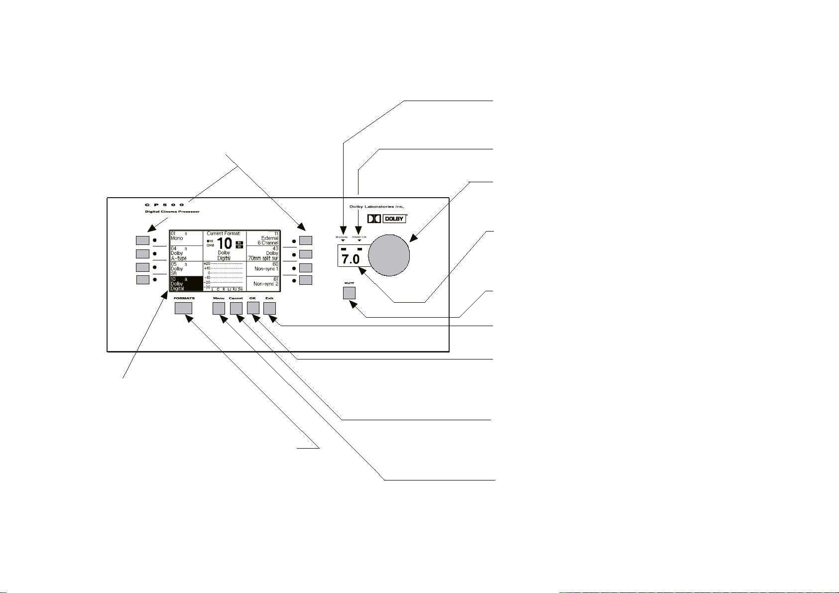
SOFT KEYS 1 - 8
Used to select the function shown
next to the switch in the front panel
display.
BYPASS INDICATOR
Indicates continuous red when unit is in
bypass mode.
MUTE ON INDICATOR
Flashes when mute is activated.
MAIN FADER/MULTI-FUNCTION CONTROL
Controls sound level and also is used for
data selection in menu operations.
(SK1)
(SK2)
(SK3)
(SK4)
FRONT PANEL DISPLAY
FRONT PANEL DISPLAY
Displays format and menu
screens.
FORMATS KEY
Used to switch to format
selection screen.
(SK5)
(SK6)
(SK7)
(SK8)
FADER LEVEL DISPLAY
Displays fader setting. Ranges from 0 to 10.
Normally set to 7.0 This display shows '- -'
when in data entry mode.
2-2
MUTE KEY
Mutes output to all channels when activated.
EXIT KEY
Used to select the previous menu.
OK KEY
Used during pop-up menu operations. Selects
option currently in pop-up window selection box.
Also stores currently displayed data.
CANCEL KEY
Used during pop-up menu operations. Cancels
pop-up menu operation and restores the
previous menu or data.
MENU KEY
Used to return to the top of the menu tree.
Page 10
2-3
CANCEL
Many of the screens used during set-up or diagnostics contain a "Pop-Up" screen
within the main screen. The CANCEL key is used to cancel the current pop-up
operation being performed and restore any data that was changed during the pop-up
screen operation to its original value.
OK
This key is used to accept and store the current setting in a pop-up screen.
EXIT
This key is used to signal completion of an adjustment procedure or select the
previous screen.
Other Controls and Indicators
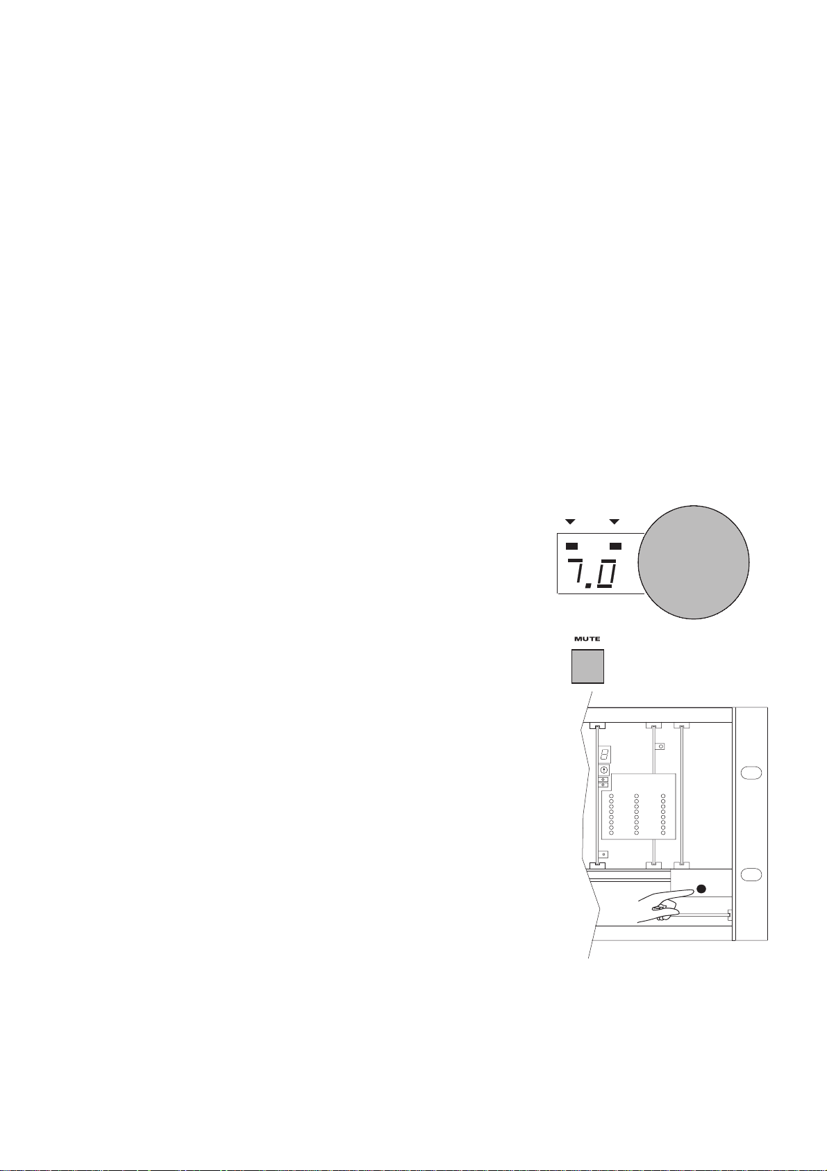
FADER LEVEL INDICATOR
To the right of the main display is another window
showing the selected fader level. As with previous
generations of Dolby cinema processors, a fader setting of
"7.0" is the nominal correct operating level. This setting
matches the level used during the film's production. As the
main fader is turned, the numbers on the display will
move from zero to ten. The knob rotates continuously
with no end stops. The number displayed will always
indicate the current level setting.
Bypass
Mute On
MUTE
The MUTE key is used to fade the sound down and up
without disturbing the fader setting. A green LED, MUTE
ON, located above the fader level display will flash,
indicating that the CP500 outputs are muted. Pressing the
MUTE key again will cancel muting.
BYPASS
A BYPASS LED is located to the left of the MUTE ON LED.
As with other Dolby cinema processors, the CP500 utilizes a
separate back-up power supply which is used during
emergency operation. If the CP500 is operating in bypass
mode, this red LED will come on (not flashing). If there should
be a failure, the system can switch into bypass mode either
temporarily or permanently. A manual bypass push-button is
located inside the front panel on the right hand side of the unit.
The switch turns off the main power supply which enables the
separate bypass power supply.
POWER/ BYPASS
Page 11

2.2 System Password
Many of the CP500 alignment functions are normally protected from unauthorized
access by using a system password. A password is stored by the installation
technician after the system is aligned in order to block any changes to the B-chain
alignment, calibrated level settings, or time delays. Knowledge of this password is
required to enter these special CP500 menus.
2.3 Normal Operation
2.3.1 Power On
After initial installation, the power-up state of the unit may be selected from the
following choices. Each time the CP500 is connected to power or switched on, it
automatically sets itself to the selected "wake-up" state:
2-4
x
Projector 1 or 2 selected by the installation technician.
x
Front-panel main fader or auditorium fader (see manual section 2.3.4)
activated and set to the last fader setting before power was turned off.
x
The film sound format which was active when power was removed, or
the film sound format previously stored as the "wake-up" format. (The
format options can be set using the procedure described later in this
section.)
If power has been removed for longer than approximately one week, the wake-up
state is
x
Projector 1 selected. (The "wake-up" projector may have been set to
Projector 2 by your installation technician.)
x
Front-panel main fader activated and set to the last fader setting before
power was turned off
x
Format 01 Mono
When power is first applied, the first screen which
appears displays the revision level of the software.
Next, a brief "Loading System" message is
displayed.
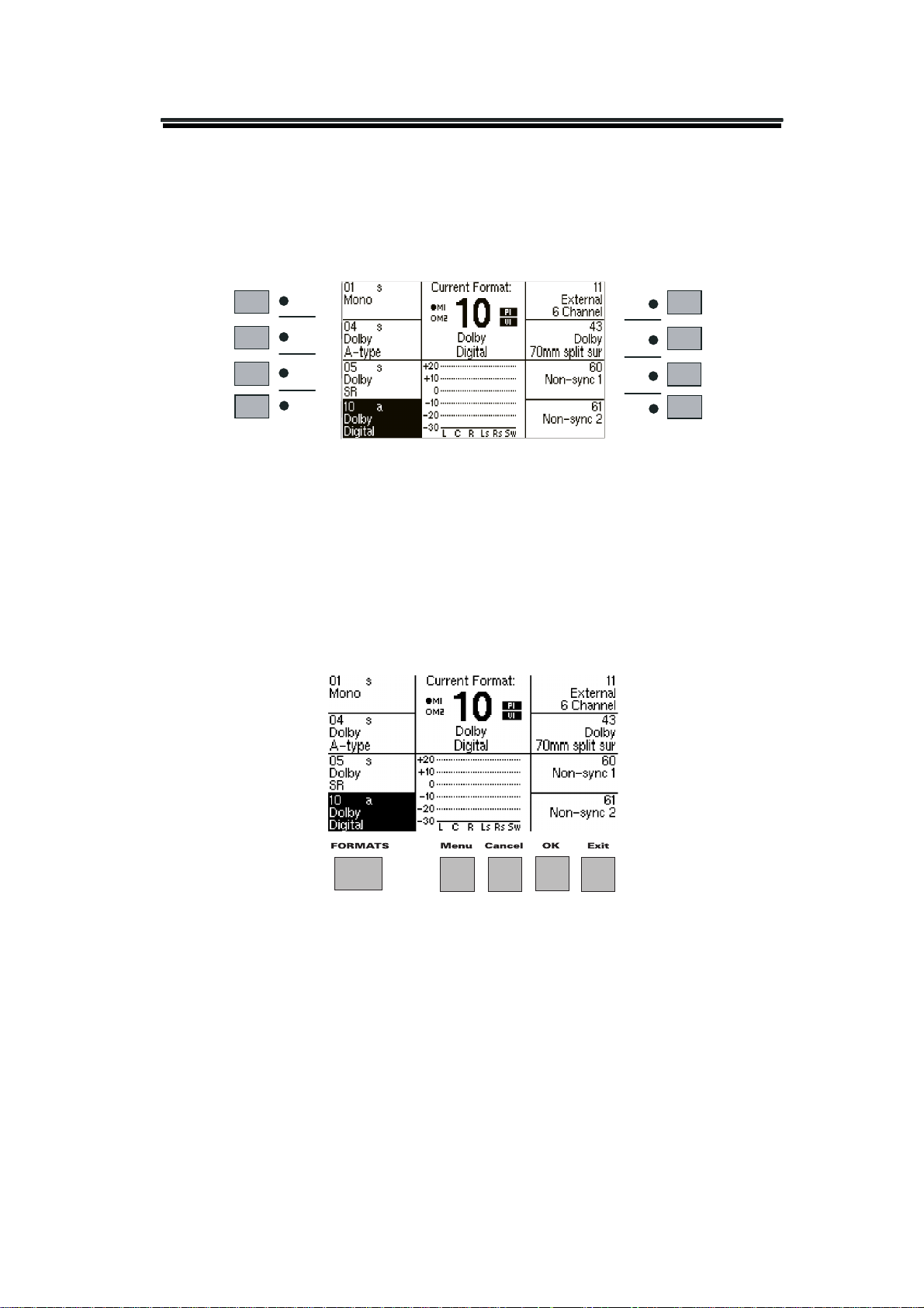
In a few seconds, the Current Format screen
appears. This is the normal screen, and the only
screen you will need for ordinary purposes.
NOTE:
The exact formats and their order on the
your screen may be different from the figure here if
Custom Screen has been selected.
Page 12

2-5
2.3.2 Format Selection
Select the desired film soundtrack format or your non-sync source by pressing the
appropriate softkey. The LED next to the key illuminates, the text next to the
softkey is reversed (dark), and the format number appears under Current Format to
confirm that the format was selected. Common formats are as follows:
x
01 Mono: for all optical prints of any vintage with conventional mono
optical (“Academy”) soundtracks.
x
04 Dolby A-type: for Dolby releases, except those marked SR or Digital.
x
05 Dolby SR: for releases marked as having a Dolby SR (Spectral
Recording) soundtrack or for Dolby Digital prints if your CP500 is not
equipped with digital playback capability.
x
10 Dolby Digital: for Dolby Digital releases. The digital data is clearly
visible between the film perforations next to the analog sound track.
x
11 External 6ch: for selecting any six-channel external sound source.
(Your CP500 must be equipped with an optional Cat. No. 685 card.)
x
43 Dolby 70 mm split surround: for 70 mm films with 6-channel
magnetic soundtracks. (Your CP500 must be equipped with optional cards.)
x
60/61 non-sync1/2: for your intermission music tape or a CD player.
The film soundtrack format numbers used on the CP500 display (and also on
models CP45, CP65 and CP200) often appear on the film can and leader. If these
numbers are not supplied and you are not sure if a print is mono or stereo optical,
see Appendix A for a means to distinguish the various types of soundtracks.
2.3.3 Automatic Selection of Dolby Digital Format
CP500s equipped with versions 1.30 or later software are set up to sense the
presence of Dolby Digital data on the film and automatically switch to Dolby
Digital from any other film format. This section of the manual describes how to use
this feature.
Operation With Standard Format Screen
The Standard format control screen on the CP500 comes with Formats 01 (Mono),
04 (A-Type), and 05 (Dolby SR) set up so that auto-digital will occur from them.
These formats are marked by an “s” (for sources) on the screen.
Page 13
2-6
Format 10 is the format that the auto-digital system will switch to when good
Dolby Digital data is detected. It is marked with an “a” (for automatic) on the
screen. Format 10 is defined as the “target” format, in this case.
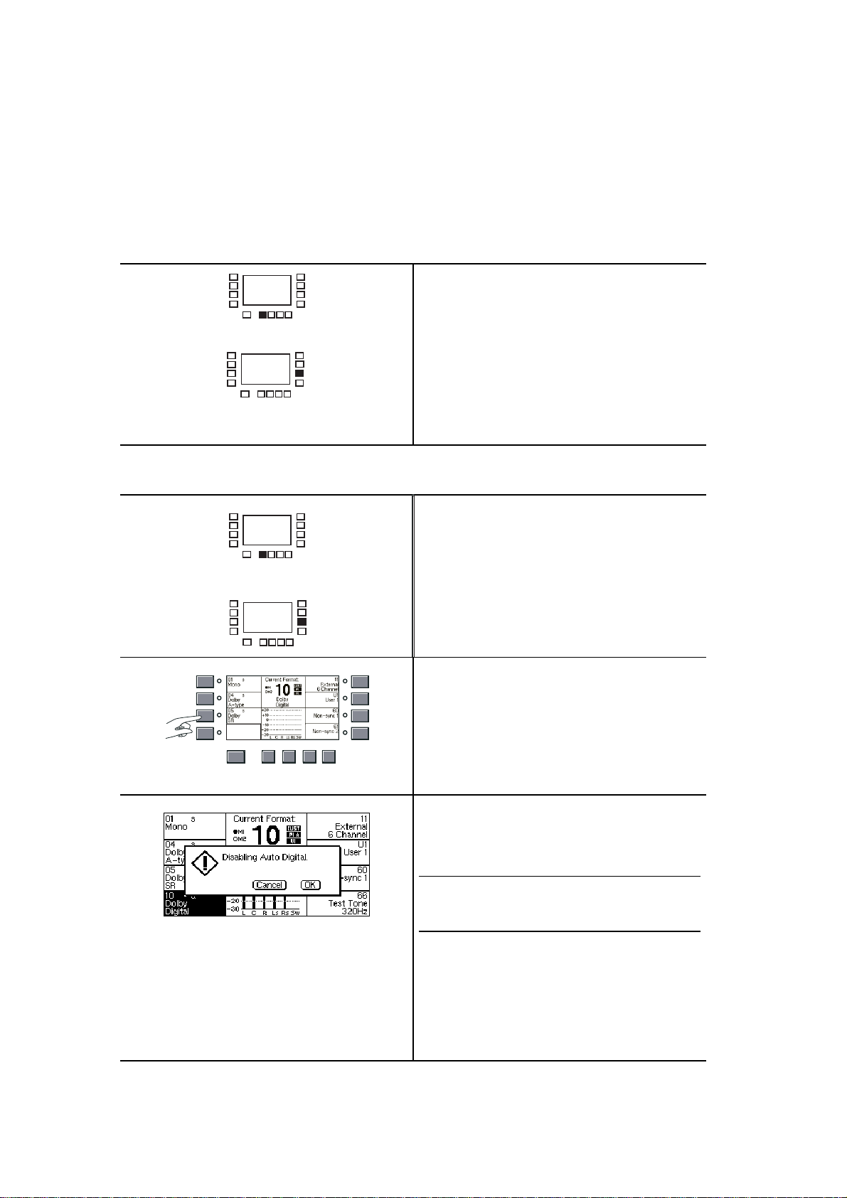
To enable the auto-digital feature:
Press Menu.
MENU
SK7
To disable the auto-digital feature:
MENU
SK7
10 a
Dolby
Digital
FORMATS
Menu Cancel OK
Exit
Then, press SK7.
Pressing SK7 alternately enables and
disables the auto-digital feature.
You may disable auto-digital operation
by pressing the MENU key and SK7.
Pressing SK7 alternately enables and
disables the auto-digital feature.
Alternately, if the unit is currently
playing digital audio in Format 10,
select Format 05 (SK3).
A dialog box will ask you if you want to
disable auto-digital operation.
NOTE
: The dialog box will not appear and autodigital will not be disabled unless the CP500 is
currently playing in Format 10.
x Press the OK key and it will disable
auto-digital.
x Press the CANCEL key and it will
leave the CP500 as it was.
Page 14
2-7
Operation with Custom Format Screen and Special Configurations
If the installation engineer has configured your CP500 to be different from the
standard screen, the same operating methods apply. Formats designated with an “s”
are source formats for the auto-digital feature, and the format(s) designated with an
“a” is the target format(s). Disabling and enabling the feature works in the same
way as described above.
2.3.3 Main Fader
The main fader (or front panel knob) on the front panel of the CP500 controls the
volume level in the theater in both the normal and bypass operating modes. When
the CP500 has been correctly installed, setting the fader to "7.0" provides the
proper level in your theater for any Dolby encoded film. It will play at the level at
which the film was mixed.
Although a minor adjustment in playback level might be required under unusual
circumstances, you should avoid significant deviations from the correct level "7.0"
established by the installer. If the playback level is set too low, dialogue will be
hard to understand; too high a level will give rise to complaints from the audience
and under extreme circumstances can damage the theater's sound system.
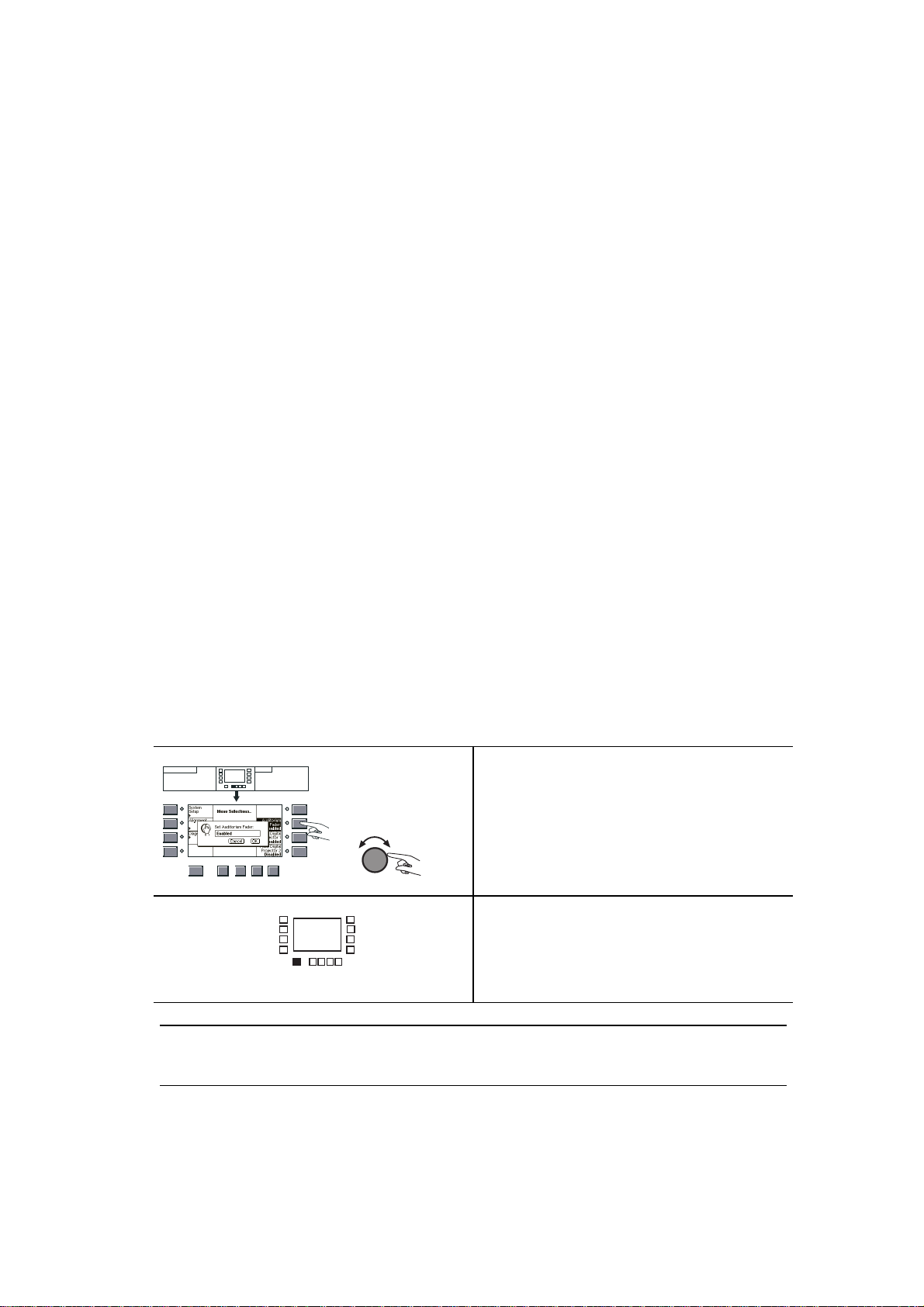
2.3.4 Auditorium Fader
If an analog (not a Dolby Cat. No. 689 Digital Remote Unit) auditorium fader has
been installed, it is activated by performing the following menu steps:
Menu Cancel OK
press:
Menu
Exit
FORMATS
key
Press the MENU key.
Press Auditorium Fader (SK6). Turn
the front panel knob to the Enabled
position.
Press the FORMATS key to return to
the format control screen. The fader
level display will show “AU”.
screen shows:
Format
Selection
FORMATS
NOTE:
faders or Cat. No. 689 remote unit faders installed in your system will be disabled. Only the auditorium fader
will be active.
When the auditorium fader is selected, the CP500 front panel main fader and any Cat. No. 734 remote
Page 15

2-8
2.3.5 Mute Function
The MUTE key is useful if the film breaks or runs out, while the projector is
active, since it suppresses the very loud signal that occurs when leaders or tails
pass through the sound gate.
When you press the MUTE key, the volume will automatically fade all the way
down on all channels. A green LED, MUTE ON, located above the fader level
display will flash, indicating that the CP500 outputs are muted. When you press the
MUTE key again, or select a new format, the volume will automatically rise to the
level set by the main fader.
Use the mute function between intermission music and projector-start to prevent
the audience from hearing annoying thumps and leader crackle at the beginning of
the show.
2.3.6 Operation With an Automation System
If the CP500 in your theater is connected to automation equipment, the format keys
and their associated LEDs may be duplicated elsewhere. In most cases, the front
panel controls of the CP500 can usually be used to override commands from the
automation system; however, as automation equipment differs from installation to
installation, check with the installer of your system if you have any questions about
its operation and whether you can easily override automation commands.
2.4 Bypass Operation
The CP500 has an independent power supply for emergency operation. If the main
power supply or processor circuitry fails, the unit will automatically switch to
bypass operation, allowing the show to continue with limited sound processing
functions. Bypass operation is signaled by the red (not flashing) bypass LED
located above the main fader level display on the front panel.
In the case of other problems, such as distortion or the loss of a channel, the bypass
mode can be selected manually by means of a push-button switch located inside
the front panel on the right hand side of the unit. For more information in selecting
bypass manually, see Section 2.4.1.
There are other components in the theater sound system that could also fail. Be
sure to refer to Section 4, Troubleshooting, any time there is a problem.
Page 16

2-9
The following occurs when the CP500 is in the bypass mode:
x
Only the front panel main fader operates, no other remote fader will work.
x
All other commands from the front panel keys are ignored by the unit.
x
The optical preamp output of the selected projector remains operational and is
fed to the CP500 output card.
x
Even when a stereo print is playing, a mono signal is fed to all the screen
speakers. Thus, you can switch to the bypass mode to keep the show going if
one of the power amplifiers fails.
x
The Dolby digital processors, A-type noise reduction circuitry, SR processors,
2:4-channel decoder, screen speaker equalizers, surround equalizers, and
subwoofer circuits are out of the signal path.
If the unit has entered bypass mode automatically due to a failure in the main
power supply or the main power source, then the front panel LEDs will be off
except the bypass LED.
If the unit has entered bypass mode automatically due to a failure in the main signal
path, then the front panel LEDs may still be on. A message on the front panel
screen will indicate the nature of the failure.
Be sure to follow the troubleshooting procedures and if necessary, call your trained
service engineer as soon as possible.
NOTE
:
The CP500 will
following areas:
x
The AC mains power to the bypass transformer or main power supply
x
The Cat. No. 661 optical preamplifier card
x
The bypass circuitry section of the Cat. No. 682 card
x
The Cat. No. 683 (optional) crossover card for bi-amplified installations
x
The bypass power transformer itself
It is strongly recommended that spares of the above cards and the transformer be kept on hand for
substitution in emergencies.
If the theater is equipped with film platters and the unused projector input on the rear of the CP500
is accessible, the projector solar cell connector can be moved from Optical 1 to Optical 2 in order to
try using the second optical preamp circuit. However, this input may not be set up correctly, so care
will be needed with the volume control.
not
operate --
even in the bypass mode
-- if there is a fault in any of the
Page 17
2-10
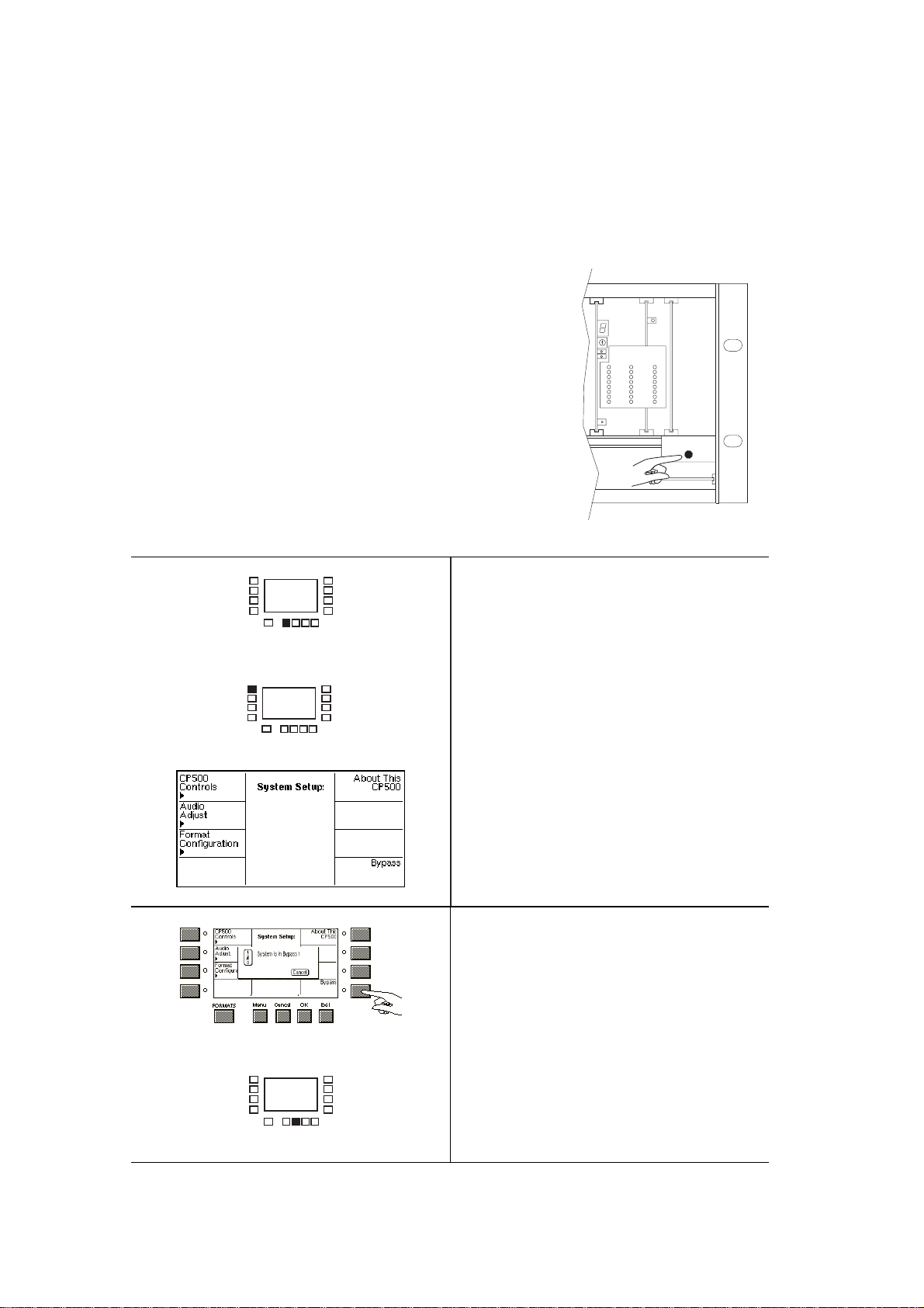
2.4.1 Manual Bypass Selection
The CP500 can be manually switched to bypass using either of two methods:
1. Open the front panel and operate the pushbutton
switch located on the right-hand side of the unit.
Use this method in an emergency situation, or
POWER/ BYPASS
2. Perform the following steps:
MENU
SK1
Press the MENU key.
Press System Setup (SK1).
Press Bypass (SK8).
A pop-up box appears, warning that the
CP500 is now set to bypass operation.
CANCEL
Press the CANCEL key to return the
CP500 to normal operation.
Page 18

2.5 Customizing Features
2.5.1 Setting the LCD Display Contrast
The Contrast level of the front panel LCD display can be adjusted by following
these menu steps:
2-11
screen shows:
Format
Selection
screen shows:
Menu
Selection
screen shows:
System
Setup
FORMATS
Menu
Cancel OK
press:
Menu
key
press:
System Setup
key
press:
CP500 Controls
key
Exit
Begin the procedure by pressing the
MENU key,
Press System Setup (SK1),
Press CP500 Controls (SK1).
Press LCD Contrast (SK1).
A pop-up box appears.
FORMATS
Menu Cancel OK
OK
Exit
Set the desired appearance by rotating
the front panel knob to adjust the
display contrast.
Then press the OK key to save the
contrast setting.
Page 19

2-12
2.5.2 Setting Mute Speed
The length of time it takes for the sound to fade from normal setting to muted
(when the MUTE key is pressed) is adjustable. To make this adjustment,
screen shows:
Format
Selection
screen shows:
Menu
Selection
screen shows:
System
Setup
FORMATS
Menu
Cancel OK
press:
Menu
key
press:
System Setup
key
press:
CP500 Controls
key
Exit
Press the MENU key,
System Setup (SK1),
CP500 Controls (SK1),
Mute Speed Adjustment (SK7).
Use the main fader to select the fade-out
time you prefer. The time displayed is
the approximate time to silence. You
can test the mute function while in this
window to see whether you are satisfied
with the setting chosen.
Press OK when you are satisfied with
the setting or press CANCEL if you
OK
wish to retain the original setting.
Press FORMATS to return to the
normal format control screen.
FORMATS
NOTE
: When the Mute function is being executed, any other control actions will be delayed for
approximately 1.2 times the selected mute time.
Page 20

2-13
2.5.3 Customizing the Format Display Screen
There are two types of Format Selection display screens. The unit is shipped in
Standard Mode, which allows selection of eight commonly used formats. There
also exists a Custom Mode which allows the user to program the softkeys to show
formats of his own choosing, along with changes to the fader setting and projector
selection for each of these softkeys.
screen shows:
Format
Selection
screen shows:
Menu
Selection
screen shows:
System
Setup
FORMATS
FORMATS
Menu
Cancel OK
Cancel OK
Menu
press:
Menu
press:
System Setup
press:
Format
Configuration
Exit
Exit
key
Begin the procedure by pressing the
MENU key.
Press System Setup (SK1).
key
Press Format Configuration (SK3).
key
Switching the format screen display
between Standard and Custom is next.
Press Format Screen (SK2).
A pop-up box appears.
FORMATS
Menu
OK
Cancel OK
Rotating the front panel knob selects
between Standard and Custom modes.
Select Custom.
Then press the OK key to complete the
action.
To program the softkeys, choose Build
Format Selector (SK3).
Exit
Page 21

2-14
FORMATS
To assign formats to the softkeys press
the Assign Formats key (SK1).
FORMATS
Menu
Cancel OK
Exit
A copy of the existing format selection
screen is displayed. Pressing any softkey
causes a pop-up box to appear, allowing
any format to be assigned to that
softkey.
This example shows the display after
SK4 has been pressed for assignment.
Rotating the front panel knob will move
the display through the formats
available.
When the desired format is shown,
select it by pressing the OK key.
OK
NOTE
:
Pressing the
the pop-up box and restores the previous format
assigned to that softkey.
CANCEL
key, removes
EXIT
OK
Continue in this fashion until all of the
desired formats are assigned to the soft
keys of your choice.
Press the EXIT key to return to the
Build Custom Format menu.
If changes have been made, a box will
appear prompting you to save or discard
the changes.
Press OK to save the new settings.
NOTE
:
Pressing the
new settings and restores the old settings.
Cancel
key discards the
Page 22

2-15
FADER SETTINGS
Assigning fader settings to the softkeys
is done in a similar fashion.
FORMATS
Menu
Cancel OK
Exit
To assign fader settings, press Assign
Fader Settings (SK2).
Once again a copy of the format
selection screen is displayed. Pressing
any softkey causes a pop-up box to
appear allowing a fader setting to be
entered for that softkey.
This example shows the display after
SK4 has been pressed to set a fader
value for SK4, Format 10, Dolby
Digital. Rotate the front panel knob to
set the fader value to be associated with
the softkey.
When the desired fader setting is shown,
select it by pressing the OK key.
OK
NOTE
:
Pressing the
the pop-up box and restores the previous fader
setting assigned to that softkey.
CANCEL
key, removes
EXIT
OK
Continue in this fashion until all the
desired fader settings have been
assigned to the soft keys of your choice.
Press the EXIT key to return to the
Build Custom Format menu. If changes
have been made, a box will appear
prompting you to save or discard the
changes.
Press OK to save the new settings.
NOTE
:
Pressing the
new settings and restores the old settings.
NOTE
:
When the CP500 switches to a format
that has no fader setting programmed, the
current front panel fader setting will remain
unchanged.
CANCEL
key discards the
Page 23

FORMATS
Menu
Cancel OK
2-16
ASSIGNING A PROJECTOR
Assigning or "linking" a projector
selection to the softkeys is done in a
similar fashion. To assign projector
Exit
selection, choose Assign Projectors
(SK5).
Once again a copy of the format
selection screen is displayed. Pressing
any softkey causes a pop-up box to
appear allowing a projector selection to
be entered for that softkey.
This example shows the display after
SK4 has been pressed to link a projector
to SK4, Format 10, Dolby Digital.
Rotate the front panel knob to display
the projector you wish to link to the
softkey.
When the desired projector is shown,
select it by pressing the OK key.
OK
NOTE
:
Pressing the
the pop-up box and restores the old projector
number assigned to that softkey.
CANCEL
key, removes
Continue in this fashion until all of the
desired projector selections have been
assigned to the soft keys of your choice.
The projector selection for each softkey
that has been assigned will appear in
bold text in the softkey box.
EXIT
OK
Press the EXIT key to return to the
Build Custom Format menu. If changes
have been made, a box will appear
prompting you to save or discard the
changes.
Press OK to save the new settings.
NOTE
:
Pressing the
new settings and restores the old settings.
CANCEL
key discards the
Page 24

FORMATS
2-17
Press the FORMATS key to return to
the format selection screen.
Notice that a small indicator (CUST)
now appears next to the Current Format
area, indicating that 'Custom' screen
mode is active.
Any fader settings and projector
selections are also displayed. In this
example, the screen tells you that the
fader setting has been adjusted to 6.5
and Projector 1 has been selected.
Page 25

MAINTENANCE AND ADJUSTMENTS
The installation of the Dolby CP500 in your theater indicates a commitment to
providing a high-quality presentation to your audiences. However, the presence of
even the very best equipment does not in itself guarantee the best results. A number
of routine maintenance and adjustment procedures, requiring no special test
equipment or technical knowledge, are necessary to realize the full potential of the
sound system on a day-to-day basis. These procedures can also prevent costly show
cancellations and service calls.
A Dolby Cat. No. 69T test film is required for proper maintenance of your sound
system. We also recommend that you keep on hand the Dolby Cat. No. 251 Jiffy
Test Film and run it regularly to check the theater sound system thoroughly (see
Appendix C).
3.1 Soundhead Maintenance
SECTION 3
3.1.1 Analog Sound System
No single maintenance procedure
is more vital to good analog sound
in the theater than regular cleaning
of the projector soundhead optics.
Use lint-free cotton swabs and
isopropyl alcohol to clean the
optical barrel lens surfaces.
Never touch or attempt to clean the
solar cell. The solar cell and its
adjustment are extremely delicate.
We strongly recommend that you
use compressed air -- readily
available in convenient pressure
cans -- to blow dirt and debris
away from the cell. But be
absolutely certain that the nozzle
never touches the cell.
Page 26

3-2
SL
L
LE
C
RE
R
SR
SR
MIX
ON
OFF
POWER
AMP
PROCESSOR
1
Bypass
Mute On
3.1.2 Dolby Level Adjustment
Proper decoding of Dolby encoded soundtracks requires careful level matching
between each channel of each soundhead and the CP500 (see Appendix C for a
discussion of why Dolby Level is important). When the CP500 is first installed, the
installer makes this adjustment for you. We recommend that you routinely check
Dolby Level, but only adjust it to compensate for the normal aging of the exciter
lamp. However, it is always necessary to adjust Dolby Level whenever an
exciter lamp is replaced.
Checking and adjusting Dolby Level requires a loop of Dolby Cat. No. 69T test
film that is available from your theater equipment supplier.
The adjustment procedure is as follows:
On Projector 1, clean the optics as
described earlier. Then, thread and play
the Dolby Tone test film Cat. No. 69T.
Ensure that the arrow is going in the
correct direction.
Switch the booth monitor to Center
channel.
Listen to the tone on the booth monitor
to identify any problems with distortion
or unwanted film playing speed
variations.
Set the Fader Level Display to read
between 4.0 and 5.0.
Page 27

3-3
screen shows:
Format
Selection
screen shows:
Menu
Selection
screen shows:
Diagnostics
FORMATS
Menu
Cancel OK
press:
press:
Diagnostics
press:
Menu
key
key
Set Dolby
Level
Exit
Begin the Dolby Level adjustment by
pressing the following:
MENU key
key
Diagnostics (SK3)
Set Dolby Level (SK2)
Auto Level (SK7)
A pop-up screen appears which allows
you to select Projector 1 or 2 as the
Dolby Tone input source.
"Projector 1"
EXIT
OK
OK
Turn the front panel knob to select
Projector 1, then press OK.
With Dolby Tone test film running, the
CP500 automatically calibrates the left
and right channels of the CP500. This
operation takes approximately 30
seconds.
When the screen reports that the
calibration is finished,
press the EXIT key.
Press OK to save the new level
calibration settings in CP500 memory.
Repeat all of the above steps for Projector No. 2, if present.
Page 28

3-4
3.1.3 Digital Sound System
The Digital Soundhead should be kept clean and free of dust and dirt for best
performance, just like the analog soundhead. Wiping the external surfaces with a
clean cloth on a regular basis will keep the head looking new. The optical path
should be inspected regularly and kept clean with a photographer’s lens cleaning
kit (available from most camera stores). Use care not to scratch the lens. The film
path (rollers and drum) should be cleaned regularly, as you would on the projector.
Acetone, carbon tetrachloride, or other dangerous cleaners should not be used.
Replacing the Exciter Lamp
The exciter lamp in the Digital Soundhead has been designed for long life and
should provide over 8,000 hours of reliable use under normal circumstances.
Routine replacement will depend on your theater’s hours of operation. To replace
the exciter lamp, carefully remove the six screws holding the rear cover/power
supply of the Digital Soundhead. Allow the lamp to cool if necessary. With the rear
cover removed, the lamp will be visible but still attached to the rear cover assembly
by its two supply wires. Slide the lamp out of its base. Carefully remove a new
lamp from the protective box. Using gloves or a clean, lint-free cloth, replace the
lamp in the socket. Be careful not to touch the bulb or inner surface of the reflector
in the lamp. If either is accidentally touched, carefully clean the area with isopropyl
alcohol when the bulb is cool. Slide the lamp back into its base in the soundhead,
replace the rear cover assembly, and tighten the six screws.
Replacement lamp:
Use only General Electric EPT
Reflector-type
42W
Dolby Part No. 34010
Page 29

3.2 Print Cleanliness
A high fidelity Dolby-equipped theater system is like a high-quality home stereo
system: it can sound only as good as the program material played through it. Just
as a good home stereo clearly reproduces the annoying pops and clicks on poorlyreceived radio signals, a good theater system reproduces pops, crackles, and other
noises from worn and dirty film prints.
If you receive a poor print from your distributor, there is little you can do except, if
possible, arrange for its replacement. But while a print is in your theater, you
should treat it with respect and care to be sure your audiences receive the best in
both sound and picture. Of greatest importance, the print should be kept as clean as
possible: when the film is played, when the print is stored between shows, and
when a platter reel is made up (if your theater is so equipped). In particular, when
individual reels are unwound to make up a platter reel, do not let the film touch
the floor or come in contact with other sources of dust and dirt.
3-5
The Dolby Digital print format has robust error correction information encoded
along with the audio data, and the CP500 uses a powerful digital error correction
technique, allowing the data to be decoded perfectly even if scratches and dirt are
present. However, best performance will be obtained if the print is kept clean.
Standard film cleaners will provide good results.
The sound quality of the digital track has properties unlike those of an analog track
with regard to print wear. With any analog track, print wear will degrade quality
more or less gradually; the more wear, the lower the quality of the sound. With a
digital soundtrack, wear will have no audible effect until the print is degraded
beyond use. By this time the picture quality is usually unacceptable too. At this
point, wear also may exceed the error correction capabilities of the decoder, and
switching to the analog Dolby SR track will occur.
DIGITAL
ANALOG
(Sound & Picture)
Quality
Number of plays
Page 30

Your theater sound system consists of a number of critical audio components in
addition to the Dolby CP500. Thus, the first step when something goes wrong with
the sound is to find the source of the problem. The troubleshooting chart, starting
on page 4-7, can be helpful.
If the troubleshooting chart is not sufficient for finding and solving the problem
right away, the procedures in the following manual sections should be helpful.
If you are unable to solve the problem using the information which follows, call
your local authorized service engineer. Appendix E contains fold-out drawings of
the circuit card locations, which will help if a phone discussion with your service
engineer is necessary.
4.1 During the Show
SECTION 4
TROUBLESHOOTING
4.1.1 If Film Sound Is Lost
1. First, check that the correct format and projector are still selected.
2. Verify that the exciter lamp(s) in both the analog and digital (if so equipped)
film readers are on.
3. Check that the system is not in mute, the main fader is set to "4.0" or above,
and that the front panel still responds to the controls.
4. If your installation uses an auditorium fader (fader display shows “AU”), check
the setting of this fader.
5. Open the front door of the CP500 and switch to Bypass using the pushbutton
switch in the lower right corner. If sound is restored, it will be playing in mono,
but you can continue the show while you try to find the source of the trouble.
6. If sound is not restored, check that bypass power is connected to the CP500. A
red LED located above the front panel knob will be on if bypass power is
present. An external bypass transformer must be connected to the CP500 and
plugged into an operational power source for Bypass to work.
7. If these methods do not restore film sound, press the bypass power switch in
the lower right hand corner behind the door again. When the Current Format
screen appears, switch the CP500 to non-sync and play your source of
intermission music. If the system operates properly in this format, there is no
problem with the equipment following the CP500 (such as power amplifiers
and loudspeakers). The problem may be in the projector(s). Double-check both
projectors, and if possible, continue the show using the other projector.
Page 31

4-2
4.1.2 If One Channel Fails or is Distorted
1. Open the front door of the CP500 and switch to Bypass using the pushbutton
switch in the lower right corner. A mono signal is then fed to all three screen
channels. If the problem in one channel persists, the power amplifier or speaker
for that channel is probably at fault. If the problem is not in the Center channel,
switch the faulty amplifier off, being sure that it is not shared with the Center
channel, and finish the show in that condition. If the Right or Left channel has
failed, it may be preferable to switch off both Right and Left power amplifiers.
2. If you are showing a mono film and the Center channel has failed or is
distorted, switch the CP500 to Bypass so that the mono signal is fed to the stillfunctioning Left and Right channels. Turn off the power amplifier for the
Center channel.
4.1.3 If Switching to Bypass Does Not Restore
Sound
1. First, check the exciter lamps, the fader setting, and the mute button. Make
certain that all components including power amplifiers are receiving AC mains
power.
2. With the unit switched to Bypass, verify that the red LED near the front panel
knob is illuminated. If it is not, bypass power may be the problem. Check that a
bypass power transformer is connected to the CP500 and plugged in to an
operating AC mains power outlet.
3. If the bypass power appears to be working, check if the signal present lights on
the Cat. No. 661 optical preamp card (third slot from the left side of the unit)
are flashing. If they are and sound is still not available, check that AC power to
the power amplifiers has not been lost.
4. If the signal present lights on the Cat. No .661 are not flashing, the circuit card
may be defective, or the bypass power section of the Cat. No 682 (second slot
from the left side of the unit) may have failed. Substitute other known good
cards as a temporary measure. If you substitute another Cat. No. 682, both the
bypass level potentiometer located on the edge of the card and jumper J902
may need to be adjusted.
4.1.4 If You Hear Extraneous Noises When Playing
a Digital Film
1. Switch the Format to analog (Format 05). If the noises persist, open the front
door of the CP500 and switch to Bypass using the pushbutton switch in the
lower right corner. If the noises still persist, check the power amplifiers as it is
unlikely that both the digital and analog parts of the system have failed.
Page 32

4-3
4.1.5 Excessive or Inappropriate Sound From
Surround Speakers
1. As an emergency measure to continue the show, switch off the surround
channel power amplifier(s). At your next opportunity, find out if the problem is
related to the film itself or the theater sound system.
The problem is most likely to be in:
x
Power amplifier gain settings;
x
Damaged loudspeakers rattling, etc.;
x
Solar cell alignment in the projector (if the problem is analog sound);
x
Cat. No. 661 optical preamplifier card (if the problem is analog sound);
x
Cat. No. 222 SR/A or Cat. No. 300 (if so equipped) Noise Reduction
cards (if the problem is analog sound).
4.1.6 On CP500s Equipped with Cat. No. 683 Electronic
Crossover
This optional board is located in the first slot on the left hand side of the unit.
No High Frequency Or Low Frequency Output
Possible causes are:
x
A high frequency speaker driver has failed
x
A low frequency speaker has failed
x
A power amplifier has failed
x
A power amplifier fuse has failed
x
The Cat. No. 683 card may have failed
High frequency driver failures are the most common cause of this problem.
If it appears that the Cat. No. 683 card is the cause of the problem, open the front
door of the CP500 and switch to Bypass using the pushbutton switch in the lower
right corner. A separate speaker crossover system is provided for Bypass operation;
however, the sound will be in mono only.
4.2 Between Shows
Open the door and look at the three LEDs at the left edge of the Cat. No. 684
system controller board. This is the horizontal board located at the bottom of the
CP500. If all three are lit, then the power supply is acceptable.
MAIN CP500 RESET BUTTON
CAT.NO.
POWER INDICATORS
684
+5V-15V+15V
NOTE:
There is no LED indicating +24V power. If the fan is running then +24V power is working.
Page 33

4-4
Next, turn off the power amplifiers so as not to disturb the audience.
The CP500 is equipped with several sets of LEDs which indicate the presence of
signals. These LEDs can assist in fault diagnosis. If you have only a small amount
of time between shows, then you may wish to perform this procedure after the
theater has closed.
NOTE:
The signals
do not
flow straight across the unit from left to right.
4.2.1 Analog Film Sound Signal Path LEDs
(Be certain that Format 04 is selected)
For playing analog films, the first LEDs in the signal path are located on the Cat.
No. 661 Optical Preamp card. This card is located on the third slot from the left in
the CP500 chassis (J3). Two LEDs near the center of the card indicate that signals
exist for the Lt and Rt sound channels from the film. The other two LEDs above
and below these indicate which projector is selected. If the center LEDs are not
flashing for normal film dialog level passages, then the problem may be one of the
following:
x
The wrong projector is selected.
x
The exciter lamp has failed.
x
The solar cell is not in the correct position on the projector.
x
This card has failed.
The second set of two LEDs for Lt and Rt are at the top of the Cat. No. 681 card,
which is the right-most full height card (J7). If the LEDs on the Cat. No. 661
(discussed above) are flashing and these LEDs are not, then either the Cat. No. 661
or Cat. No. 681 is faulty.
Next in the analog signal path are the LEDs on the Cat. No. 222 SR/A module,
located next to the Cat. No. 681 card (J4). The bottom LED of the set of four LEDs
located next to the Dolby symbol is a signal present indicator. The other three
LEDs function as a signal meter. If the Cat. No. 681 LEDs are flashing but these
are not, then the Cat. No. 681 is defective, or the Cat. No. 222 SR/A is defective.
EXCEPTION:
through the Cat. No. 300 modules rather than the Cat. No. 222 SR/A module. The Cat. No. 300s have no level
meters so no signal presence indicators are available in this configuration.
If you have a Cat. No. 668 Studio NR daughter board, the Lt and Rt signals are routed
Next in the signal path are the LEDs on the Cat. No. 675A card located 9 slots
from the right hand side of the unit (J12). This card functions as the surround
decoder. The top two LEDs indicate level in the Lt and Rt channels; the bottom
two indicate analog-to-digital converter overload in the same two channels. If
LEDs are flashing on the Cat. No. 222 SR/A but not here, then the Cat. No. 681
card, or this Cat. No. 675 is faulty.
Page 34

4-5
Next in the signal path for all formats are the LEDs on the Cat. No. 675A card that
are located seven slots from the right hand side of the unit (J14). The top six LEDs
indicate that signals are present in the respective channels. This card functions as the
equalizer card. The Cat. No. 675A, as discussed previously, shows lights, but if this
card does not, then one of the two Cat. No. 675A cards is defective.
The last point in the signal processing chain for all formats is the Cat. No. 682
Output card located in the second slot from the left hand side of the unit (J2). If all
other LEDs mentioned above are flashing but LEDs on the card are not, then the
main fader is turned down too far, or the system is muted, or the Cat. No. 662
Digital-to-analog converter card or this card is faulty.
Digital Film Sound Signal Path LEDs
All the LEDs in the analog section described above should be on as described
above, since the print also contains an analog sound track.
The first LEDs in the digital signal path are the 16 green LEDs on each of the two
Cat. No. 671 cards located in the 4th and 5th slots from the right hand side of the
unit (J16,17). These should all be on nearly all the time when playing a good
quality film print with digital soundtrack.
Note that a steady red light showing on either of these cards indicates that the card
is not working. Pushing the digital sub-system reset button located at the bottom of
the Cat. No. 673 card (third slot from the right hand side of the unit, J18) will
frequently cure this problem.
WARNING:
process is complete. This will produce a small change in sound quality and can usually be done
once or twice during a show without disturbing the audience.
Pushing digital reset will cause the CP500 to revert to analog sound until the reset
If this does not correct the problem, you can reset the entire CP500 by pressing the
button located on the left hand end of the horizontal Cat. No. 684 board on the
bottom of card rack (J8,9).
WARNING:
reset process is complete. This will produce a considerable change in sound quality and you may
not wish to do this during a show.
Resetting the system will cause the CP500 to switch to Bypass until the system
The Cat. No. 673 contains a one-character alphanumeric display. This display
normally operates as an error rate indicator. Good Dolby Digital films should play
with error rates of "5" or below. If the error rate exceeds "8", then the display will
indicate "F" and the system will revert to analog playback until the data quality
improves. This card also contains two LEDs. The lower one flashes whenever an
uncorrectable block of digital data is processed; the upper one indicates a fault
condition on the Cat. No. 673 card. In normal operation, the lower LED should
rarely if ever flash, and the upper one will remain off.
Page 35

4-6
The next LEDs in the digital sound path are on the Cat. No. 675A AC-3 Decoder
card, located two slots from the right hand side of the unit (J19). This card has
three columns of eight LEDs. The top four LEDs in each column indicate signals
present in the L, Ls, and C channels respectively. The bottom four LEDs in each
row indicate signals present in the R, Rs, and SW channels. In each group, the
bottom one is illuminated for signals of 40 dB below Dolby level or louder, the
middle two for signals very close to Dolby level, and the top one for signals 10 dB
above Dolby level and louder.
The next LEDs in the digital sound path are on the Cat. No. 675A Equalizer card,
located seven slots from the right hand side of the unit (J14). This card has eight
LEDs. The top six LEDs indicate signals present in the L, C, R, Ls, Rs, SW
channels (from the top LED). If the Cat. No. 671 discussed above shows lights but
this card does not, then the Cat. Nos. 673, 675, or 680 may be faulty, or this Cat.
No. 675A card is defective. These LEDs are also illuminated when playing
analog formats
The last card containing LEDs in the signal processing chain for all formats is the
Cat. No. 682 Output card located in the second slot from the left hand side of the
unit (J2). If all other LEDs mentioned above are flashing but LEDs on the card are
not, then the main fader is turned down too far, or the system is muted, or the Cat.
No. 662 Digital-to-Analog Converter card or this card is faulty. These LEDs are
also illuminated when playing analog formats
Bypass Signal Path LEDs
When the CP500 is operating in Bypass, the only LEDs that are active are the Cat.
No. 661 optical preamp card located 3 slots from the left hand side of the unit (J3).
They are the Projector Selected LEDs and the Lt and Rt Signal Present LEDs. If
the Signal Present LEDs are flashing, you should have sound unless the fader is
turned down or the Cat. No. 661, 682, or 683 (optional card) has failed.
4.3 Troubleshooting Chart
The following pages may assist you in finding problems with your CP500 Cinema
Processor.
Page 36

Symptom Probable Cause Recommended Action
NO SOUND AT ALL
No sound, front panel dark, no bypass
LED
No sound, and switching to Bypass
doesn’t restore sound.
OR
4-7
No power to either main or bypass systems. See if mains panel fuse or circuit breaker feeding the CP500 is blown.
Verify all power connectors are fully inserted into their sockets. If
power is present, see if CP500 bypass transformer is installed
correctly.
Verify that Cat. No. 682 card is fully seated in its connector.
Press main power switch (behind front door of CP500). If CP500 still
doesn’t come on, check fuse behind plastic door in power inlet
module on power supply housing.
Defective exciter lamp or lamp power supply.
Check that the exciter lamp is on and that the lamp power supply is
operating. If not, fade up background music and transfer the reel to the
alternative projector and continue the show until the exciter lamp can
be replaced. Call service engineer.
No sound, front panel dark, red Bypass
LED is on and system is already in
Bypass
No sound, front panel normal.
Projector selection wire/switch is faulty.
No signals coming from stereo solar cells.
Power amplifiers switched off.
Malfunction in the CP500.
Above problems plus wrong format, system
muted, fader turned down. If fader display reads
“AU”, check where the auditorium fader is set.
If the front panel indication (P1, P2) for the currently active projector
is not correct, check that the projector selector switch wiring is held
firmly under the screw terminals on the Phoenix connector on the
back panel of the processor. In addition, check that the switch is
operating properly.
Check that the signal present LEDs on the Cat. No. 661 optical
preamp are flashing while film is projected. If not, there is no signal
from the solar cells or the Cat. No. 661 has failed.
Check power feed to power amplifiers for blown circuit breaker or
fuse or accidental disconnection.
Substitute Cat. Nos. 661, 682, 683 (if so equipped). See block diagram
and earlier parts of the troubleshooting section.
Check same components as mentioned above. Then verify selected
format, mute status, and fader setting. If no formats produce sound, a
number of cards may be at fault. See block diagram and LED fault
tracing instructions.
Page 37

Symptom Probable Cause Recommended Action
NO SOUND IN SOME
FORMATS
No analog film sound (Formats 01,04,
05). Front panel normal, but Dolby
Digital sound OK and non-sync OK.
No Dolby Digital sound (Format 10).
Front panel normal, analog sound OK.
No sound on external six track input
(Format 11, 70mm, external DA20, or
other multi-channel sound sources)
Front panel normal.
No sound in non-sync
Red Bypass LED lit. Front panel dark.
There is sound.
4-8
The analog exciter lamp or power supply may have failed
or the wrong projector may be selected. Solar cell
connections may be loose or damaged. The Cat. No. 661
optical preamp may have failed.
Digital exciter lamp/LED not working,
Digital subsystem, non-Dolby Digital print being played,
film not threaded correctly in reader, reader failure
Cat No. 685 card defective. Wrong format, external
device not receiving good data.
Non-sync source not working, non-sync level pots too far
down (on Cat. No. 681 card), faulty Cat. No. 681. If nonsync is a user format, is the input from Non-sync 1 or
Non-sync 2? Which channels are the signals being sent
to? Are those power amplifiers working?
System is in Bypass operation. Turn on the CP500 with the push switch at the lower right
If signal present LEDs on the Cat. No. 661 (J3) are not
flashing, verify exciter operation and solar cell connections
as described above. Substitute known good Cat. No. 661.
Verify that the exciter lamp or LED in the digital reader is
on and that the print you are playing has Dolby Digital
information on it and is correctly threaded through the
digital reader. If the CP500 will still accept a Format 10
command, the DA20 subsystem is probably still working.
Check external device for audio output. Substitute known
good Cat. No. 685.
Verify output of non-sync source. Determine from front
panel meters which channels the output is directed to and
verify that power amplifiers and speakers for those
channels are working. After checking the above, adjust
non-sync level pots on Cat. No. 681, turning both left and
right channels by equal amounts.
hand corner behind the front door. Check that the power
cord to CP500 is securely plugged in to a working power
source. Check fuse behind plastic door on AC mains power
inlet module of CP500. Call service engineer if none of
these steps fixes the problem.
Page 38

Symptom Probable Cause Recommended Action
FADER PROBLEMS
Fader level display indicates “AU” and
front panel fader has no effect
Fader level display changes when no
change in CP500 front panel fader has
been made
CONTROL PROBLEMS
CP500 won’t accept a format, gives
circle/slash symbol
4-9
Auditorium analog fader selected. Select front panel fader. In the screen menu structure, go to MENU/System
Setup/CP500 Controls and disable the auditorium fader.
This will restore control to the main fader and any digital
remotes that are connected.
Remote fader is being operated;
If in Custom screen, new format with different fader
setting selected
CP500 doesn’t have the optional modules needed for that
format, or that part of the system is not working. For
example:
NOTE
: CP500 remote faders are always active. Disconnect
remote to disable it.
Obtain and install the necessary modules. If they are
already present, ensure that they are firmly seated in their
connectors.
Format 10 requires the digital subsystem modules
Format 43 requires six channel A-type NR
Format 11 requires Cat. No. 685 6 CH ADC.
CP500 reads “Not Available” when
Format 10 is selected and stays in format
05, marked with exclamation point.
CP500 refuses any format selection Format selection switch for format you are using is stuck
No Dolby Digital data available-non Dolby Digital print,
projector not running, data blocks badly damaged.
down.
Digital modules: Cat. Nos. 670,671 (two),673,675A,860.
Gently pry button up.
Page 39

4-10
Symptom Probable Cause Recommended Action
RUMBLES, WHISTLES,
HUM etc. IN SOUND
Rumble in sound, regardless of format Audio grounding scheme may need changing. Call service engineer.
Whistles in sound Audio grounding scheme may need changing. Call service engineer.
Hum (power line frequency) in sound Malfunctioning exciter lamp or lamp power supply.
Cover the solar cells with a business card or other opaque
object. Do NOT touch the cells and do NOT disturb the
position of the cell bracket!
• If the hum disappears, the problem is in the exciter
lamp.
Stray light striking the stereo solar cells.
• If hum still persists, turn out all lights in the booth to
check if stray light is striking the cells. If the hum
disappears, turn on booth lights that are usually on
during projection, one at a time, until you detect hum
again. Redirect the light from the offending source or
keep it off during a showing. If the hum still is present,
the problem is either in the grounding or wiring or in
the CP500. Call your service engineer.
Page 40

Symptom Probable Cause Recommended Action
TROUBLE IN ONE OR
MORE CHANNELS
4-11
One channel fails. Defective power amplifier, external crossover, or
wiring for that channel.
Malfunctioning module in CP500.
The sound from one channel is distorted
(you can detect the distortion at the booth
monitor at normal listening level).
Defective power amplifier for that channel.
Defective speaker for that channel. (Booth sound
is OK but sound in the auditorium is bad).
Malfunctioning card in CP500.
Place the CP500 in bypass. All three screen speakers should
become active. If not, there is a fault in the power amplifier,
external crossover, or wiring for the missing channel.
Check if the amplifier concerned is on and check for blown
fuses.
Check that the wiring from the CP500 to the amplifier or the
loudspeaker wiring have not been broken or disconnected; check
that the screws connecting the wiring on the back panel are
properly tightened..
If the power amplifier and the wiring are satisfactory, the
problem is a malfunctioning module in the CP500; switch to
bypass and call service engineer.
Check if amplifier is on and if its fuse(s) is OK.
Check speaker.
Check that the cards are all properly seated in their connectors.
Wiring from the stereo solar cell to the CP500.
Check that the wiring from the stereo solar cell to the CP500 has
not become damaged and that the solder connections to the
fanning strip are secure. Check that the D connector for the solar
cell is firmly plugged into the CP500.
Call service engineer if wiring problems are found.
Page 41

4-12
Symptom Probable Cause Recommended Action
The sound from two or more channels is
distorted (you can detect the distortion at
the booth monitor at normal listening
Malfunctioning 2-channel power amplifier. If two distorted channels are served by the same 2-channel
amplifier, the problem may be in the amplifier. See the
manufacturer's instructions.
level).
Call service engineer.
When a stereo film is projected, the sound
appears to be coming from the wrong
The A-chain has become misaligned. Check Dolby level calibration.
Call service engineer.
speakers.
Sound from the front (screen) channels is
The A-chain has become misaligned.
Call service engineer.
leaking into the surround channel.
Surround sound delay set improperly.
Surround sound level set too high.
Call service engineer.
Call service engineer.
You hear an echo in a small theater. Surround sound delay set improperly. Call service engineer.
The sound level in bypass is higher or
lower than the normal sound level.
Adjust with the front panel knob since other parts of the
system may be malfunctioning.
Call service engineer.
Page 42

4-13
Symptom Probable Cause Recommended Action
There is distortion when you play non-
The non-sync source is introducing distortion.
sync sound, but sound from the film is not
distorted.
Defective Cat. No. 681 board
Non-sync sound is heard in other formats The non-sync source is set for too high an output level or
there is a balanced / unbalanced wiring problem.
Sound from a mono film is distorted, as is
Malfunctioning power amplifier.
sound from the center channel of a stereo
film.
Malfunctioning loudspeaker.
Change the non-sync selection in case the track being
played is distorted. If you have control of the output level of
the device (cassette deck, CD player, etc.), it will be useful
to turn down its volume especially if you have to operate
the non-sync with the fader a long way below 7. If this does
not help, try a different device. If the distortion goes away,
you have found the problem. If changing both the device
and the selection does not eliminate the distortion, the
problem is in the CP500, probably on the Cat. No. 681.
Call service engineer.
Turn down non-sync source level, if possible, and call
service engineer. If turning the non-sync source down
doesn’t correct the problem, turn it off if possible during the
show.
Interchange power amplifiers to determine if distortion is
still present.
Interchange speakers to determine if distortion is still
present.
Page 43

Symptom Probable Cause Recommended Action
CHANGEOVER AND
CONTROL TROUBLES
Projector changeover command does not
change to sound output of the selected
projector and the front panel LEDs do not
light according to the projector selected.
4-14
Defective changeover relay or switch.
Defective wiring from relay or switch to terminals on rear
of the CP500.
If possible, check that the relay or switch contacts actually
open and close as the changeover command is issued
several times.
Check that the wiring has not been damaged and that
connections are firmly made at both ends.
With optional automation connected to the
CP500:
The CP500 freezes into one format and
does not accept any other selected format
when you press the front panel switches.
With optional remote control unit Cat. No.
689 connected to the CP500:
The CP500 freezes into one format and
does not accept any other selected format
when you press the front panel switches.
Defective Cat. No. 661 optical preamplifier.
Incorrect wiring to D-connector plugged into CP500 or
defective or incorrectly programmed automation
equipment.
Incorrect wiring to remote box connector plugged into
CP500 or defective Cat. No. 689.
Call service engineer.
Unplug the D-connector from the back of the CP500. If
you can exercise local control over the CP500, the
problem is in either the wiring to the automation
equipment or the automation equipment itself. Call service
engineer.
If you cannot exercise local control over the CP500 even
with the automation equipment disconnected from the
CP500, switch to bypass and call service engineer.
Disconnect the Cat. No. 689 cable from the CP500. If you
can exercise local control over the CP500, the problem is
in either the wiring to the remote unit or the remote unit
itself. Call service engineer.
If you cannot exercise local control over the CP500, even
with the remote unit disconnected from the CP500, switch
to bypass and call service engineer.
Page 44

4-15
You can hear pops and thumps during
projector changeover.
If your projector changeover relay power is DC, a diode
should be soldered across the winding of the relay to
prevent noise from the relay winding from leaking into the
audio wiring. This diode may be missing or defective.
If your projector changeover relay is AC, a capacitor
soldered to the relay coil terminals may be defective.
Malfunctioning Cat. No. 661 optical preamplifier card.
If possible, check that the diode is installed across the
relay winding. If you are familiar with such electronic
components, check to see that it is not blown. If the diode
is not present or if it appears to be blown, install a good
diode. Activate the changeover and use a multimeter to
find the polarity of DC that appears on the relay coil.
Install the diode with the band end soldered to the
terminal that is positive when measured with the meter.
The diode should be a 1N4004 (1 Amp, 400 V), or a
1N4008 (1 amp, 800 V diode) or equivalent.
Install a .01µF 600V capacitor to the relay coil terminals.
Call service engineer to correct the malfunction.
Page 45

APPENDIX A
a
a
a
a
a
a
a
a
a
a
aa
HOW TO IDENTIFY SOUND TRACKS ON PRINTS
A Dolby Digital film print or a stereo optical print (A-Type or SR), or a mono
optical print should be identified as such on both the film can and leader.
However, with handling, the identification may be lost. If you are not sure if
you have a stereo analog print, play a reel and find a section with music and/or
effects only (on dialogue or narration, stereo soundtracks look much the same
as mono soundtracks). Examine the soundtracks closely; on music and effects,
the two soundtracks will appear to be different on a stereo print; on a mono
print they are identical. Alternatively, while the film is playing, open the front
panel and check the signal-present LEDs; the left, center, and right LEDs will
flicker regularly if the print is stereo; the center LED will predominate if the
print is mono. If you specified a stereo print and received a mono print in error,
be sure to check with your local exchange or the film distributor.
Dolby Digital Print
The digital data
blocks are clearly
visible between
perforations next to
the analog track. The
analog track is Dolby
SR encoded.
There is no way to tell by visual inspection if a stereo print has been encoded
with a surround channel or whether it is Dolby A-type or SR encoded.
However, all but a few early Dolby Stereo releases do have a surround channel.
The majority of prints are now Dolby SR encoded. If you are in doubt, play the
print in format 04 Dolby A-type until you have a chance to listen to the track
and compare playback quality in formats 04 and 05.
Analog Stereo Print
Clear differences
between channels will
be seen in some places
along the track.
Mono Print
Both tracks are the
same.
Page 46

DOLBY TEST AND DEMONSTRATION FILMS
Several test and demonstration films produced by Dolby Laboratories are available
from your equipment supplier. For proper system maintenance, the Cat. No. 69T
test film is required and the Cat. No. 251 Jiffy Test Film is strongly recommended.
The Cat. No. 69T test film should be formed into endless loops for ease of use.
Other test films (Cat. Nos. 69P, 97, 151, 566) are for use only by a trained engineer
with special test equipment. They are mentioned here so you know what they are
should you ever come across them.
B.1 Cat. No.69T: Dolby Tone
APPENDIX B
This film is required to maintain your theater system. The Dolby Tone recorded on
the film is for automatic calibration of the operating level in the CP500. This
simple procedure must be performed whenever an exciter lamp is replaced and
should also be performed from time to time to compensate for the normal aging
(and reduced light output) of exciter lamps.
B.1.1 Why Adjusting Dolby Level Is Important
The accurate reproduction of Dolby soundtracks requires that the decoders in the
theater act as precise mirror images of the encoders used when the tracks were
recorded. This precision is ensured in two ways. First, Dolby system circuits are
manufactured to very close tolerances. Second, a reference Dolby Level has been
established so that any Dolby-encoded recording can be accurately decoded by any
Dolby decoder of the same type.
Remember that Dolby circuit action in both recording and playback is leveldependent. Loud signals are untouched, while low-level signals are boosted during
recording and attenuated during playback, by an amount that depends on their
level. How does the playback Dolby decoder know when, and by how much, to
attenuate the previously-boosted signals? The answer is that it doesn’t know. When
the decoder sees any particular playback voltage, it assumes what happened when
the recording was originally encoded. For that assumption to be accurate, however,
it was necessary when Dolby noise reduction was first developed to establish a
standard reference level to which all encoded recordings and all decoding circuits
could be calibrated.
Page 47

B-2
This is where the Dolby Level Tone on the Cat. No. 69T test film comes into play.
The tone on this film is very carefully recorded at the standard reference Dolby
Level. When you perform the Dolby Level calibration on the CP500 as this film
plays, you are making sure that the tone on the film is converted to a standard
reference voltage at the inputs to the decoders. Thereafter, signals from Dolby
soundtracks will be converted to the correct voltages for mirror-image decoding.
As long as the proper Dolby Level procedures are followed, any Dolby-encoded
soundtrack recorded anywhere in the world will be accurately decoded by any
Dolby cinema processor anywhere in the world.
Although large level-matching errors can cause audible decoding errors (such as
frequency response changes), both Dolby A-type and Dolby SR are tolerant of
errors smaller than about 2 dB. Thus, Dolby Level must be readjusted only if there
is a significant change in the reproduction chain before the Dolby decoding circuit.
In the theater, exciter lamp brightness is the variable most likely to affect Dolby
Level calibration. The voltage present at the inputs to the decoder circuitry is
directly proportional to the amount of light that passes through the slit and
soundtracks onto the solar cell. Therefore, significant changes in exciter lamp
brightness – likely as the lamp ages over time or when a new lamp is installed –
should be compensated for by running the Dolby Level calibration procedure.
B.2 Cat. No. 251: Jiffy Test Film
JIFFY
TEST FILM
Cat. No. 251 SR•D—A subjective film for testing theatre sound
RECORDED IN
Running Time:
Picture format:
Sound formats:
10
digital
Dolby Laboratories Inc. • 100 Potrero Avenue
San Francisco, CA 94103-4813
Telephone 415-558-0200 • Facsimile 415-863-1373
Dolby, the Double-D symbol and Dolby Stereo are trademarks
of Dolby Laboratories Licensing Corporation
This eight-minute test film is strongly recommended to help keep your system
sounding its best. No special equipment is required because the tests have been
specifically designed to permit subjective judgment by ear. Each test is described
by either a male or female voice and is supplemented by captions on the screen
which help identify the causes of sound system problems. Visual checks are also
included to assist in identifying some picture projection problems.
6 minutes
1.85:1 widescreen or
2.35:1 anamorphic
05
analog
S96/10117/11146
Page 48

B-3
Tests provided on the Cat. No. 251 include: Level Set, Channel Identification,
Channel Level and Loudspeaker Equalization, Loudspeaker and Amplifier
Condition, Projector Wow and Flutter, Overall System Performance, Visual
“Quick-checks,” and a Noise and Interference Test.
Duration: 8 minutes
Picture format: 35mm color, can be screened either 1.85:1
wide-screen or 2.35:1 anamorphic
Sound format: Dolby Digital, and Dolby SR
B.3 Cat. No. 69P, Cat. No. 97, Cat. No. 151, and
Cat. No. 566 Test Films
These specialized test films are for use only by trained engineers with special test
equipment and need not be kept on-hand at the theater. The Cat. No. 97 is used for
aligning stereo solar cells in projector soundheads, while the Cat. No. 151 is used
to set the level of the surround speakers relative to the screen speakers.
The Cat. No. 566 is used to measure the uniformity of light along the slit of the
sound lens assembly in the projector.
B.4 Cat. No. 1010, Cat. No. 1011, and
Cat. No. 1012 Test Films
These specialized test films are for use only by trained engineers with special test
equipment and need not be kept on-hand at the theater. They are used to set up the
digital sub-system in the CP500.
Page 49

Thanks to such developments as multichannel sound, the motion picture viewing
experience today is more exciting and involving than ever before. And what the
audience hears today is very much the result of a continuing effort to improve film
sound originally undertaken by Dolby Laboratories more than twenty years ago.
Indeed, the evolution of motion picture sound over the past two decades is, in great
part, that of Dolby film sound technologies.
C.1 Optical Sound
The photographic or “optical” soundtrack was the first method of putting sound on
film, and today it remains the most popular.
An opaque area adjacent to the picture contains narrow, clear tracks that vary in
width with variations in the sound. As the film is played, a narrow beam of light
from an exciter lamp in the projector’s soundhead shines through the moving
tracks. Variations in the width of the clear tracks cause a varying amount of light to
fall on a solar cell, which converts the light to a similarly varying electrical signal.
That signal is amplified and ultimately converted to sound by loudspeakers in the
auditorium.
APPENDIX C
THE EVOLUTION OF DOLBY FILM SOUND
Several advantages of optical sound have contributed to its universal acceptance,
the foremost being economy. For one thing, the soundtrack is printed
photographically on the film at the same time as the picture. For another, the
soundtrack can last as long as the picture, which—with care—can be a long time
indeed. A further benefit is that the optical soundhead within the projector is itself
economical and easily maintained.
Motion pictures with sound were first shown to significant numbers of movie-goers
in the late 1920s. By the mid-1930s, the “talkies” were no longer a novelty, but a
necessity, and many thousands of theaters were equipped in that short time to show
films with optical soundtracks. This phenomenally rapid acceptance of a
sophisticated new technology was not without drawbacks, however. Equipment
was installed in theaters so rapidly that there was no time to take advantage of
improvements which were occurring on an almost daily basis.
A good example is loudspeaker design. The first cinema loudspeakers had very
poor high-frequency response. Speakers with superior high-frequency capability
became available within just a few years. But there was no time to retrofit the
original systems with new units, because engineers were too busy equipping other
theaters with their first sound installations.
This caused a dilemma for soundtrack recordists. Should the tracks be recorded to
take advantage of the improved speakers, or should they be prepared to sound best
on the many older installations already in place? Given that it was impractical to
release two versions of a given title, the only alternative was to tailor soundtracks
Page 50

C-2
to the older speakers. The result was to ignore the improved high-frequency
response of the newer, better units.
To forestall compatibility problems, in the late 1930s a de facto standardization set
in, the theater playback response that today is called the “Academy” characteristic.
Theater owners knew what to expect from the films, and therefore what equipment
to install. Directors and sound recordists knew what to expect from theater sound
systems, and thus what kind of soundtracks to prepare. The result was a system of
sound recording and playback that made it possible for just about any film to sound
acceptable in any theater in the world. It was also a system, however, without the
flexibility to incorporate improvements beyond the limitations that existed in the
1930s.
Even with these limitations, for years optical film sound provided higher quality
sound than home phonographs and radios. But by the late 1960s and early 1970s,
superior hi-fi stereo systems had been installed in so many homes that a significant
and influential proportion of the moviegoing public was used to better sound at
home than could be heard in the theater.
C.2 Magnetic Sound
In the 1950s, a new method of putting sound on film was introduced as an
alternative to the optical soundtrack. After the picture is printed, narrow stripes of
iron oxide material similar to the coating on magnetic recording tape are applied to
the film. The sound is then recorded on the magnetic stripes in real time. In the
theater, the film is played back on projectors equipped with magnetic heads, similar
to those on a tape recorder, mounted in a special soundhead assembly called a
“penthouse.”
Magnetic sound was a significant step forward, and at its best provided much
improved fidelity over the conventional optical soundtrack. Magnetic sound also
permitted the multiple tracks required by stereophonic sound. The voice of an actor
appearing to the left, center, or right of the picture could be heard coming from
speakers located at the left, center, or right of the new wide screens also being
introduced at this time. Music took on a new dimension of realism, and special
sound effects could emanate from the rear or sides of the theater. The two main
magnetic systems adopted were Twentieth Century Fox’s four-track 35 mm
CinemaScope system introduced for The Robe, and the six-track Todd-AO system
first used for such 70 mm films as Oklahoma! and Around The World in 80 Days.
Many theaters were equipped for magnetic sound in the 1950s, even though the
playback equipment was expensive. Many films were issued with magnetic
soundtracks, although magnetic prints were, and remain, much more expensive
than optical sound prints (35 mm magnetic prints cost at least double their optical
equivalents, and today’s 70 mm magnetic prints cost up to fourteen times as much).
Page 51

By the 1970s, however, the film industry declined overall, with fewer films and
fewer theaters. The expense of magnetic release prints, their comparatively short
life compared to optical prints, and the high cost of maintaining magnetic theater
equipment led to a massive reduction in the number of magnetic releases and
theaters capable of playing them. Magnetic sound came to be reserved for a only
handful of first-run engagements of “big” releases each year. By the mid-1970s,
movie-goers were again usually hearing low fidelity, mono optical releases again,
with only an occasional multitrack stereo magnetic release.
C.3 Dolby Gets Involved
The situation that prevailed in the mid-1970s completely changed by the late
1980s. Thanks to new technology and a turnaround in the financial decline of the
industry, almost all major titles today—accounting for 80% of the boxoffice—are
released with wide-range multichannel stereo soundtracks.
C-3
The breakthrough was the development of by Dolby Laboratories of a highly
practical 35 mm stereo optical release print format originally identified as Dolby
Stereo. In the space allotted to the conventional mono optical soundtrack are two
soundtracks that carry not only left and right information as in home stereo sound,
but also information for a third center-screen channel and—most notably—a fourth
surround channel for ambient sound and special effects.
This format not only enabled stereo sound from optical soundtracks, but higher
quality sound as well. Various techniques are applied both when the soundtrack is
recorded and when it is played back to improve fidelity. Foremost among these is
Dolby noise reduction to lower the hissing and popping associated with optical
soundtracks, and loudspeaker equalization to adjust the theater sound system to a
standard response curve.
All this means that these prints can be reproduced in theaters with Dolbymanufactured cinema processors with far wider frequency response and much
lower distortion than conventional soundtracks. In fact, the Dolby optical format
has led to a new worldwide playback standard (ISO 2969) for wide-range stereo
prints, just as the “Academy” characteristic applies for mono prints.
An important advantage of the Dolby optical format is that the soundtracks are
printed simultaneously with the picture, just like mono prints. Thus a four-channel
stereo release print costs no more to make than a mono print (although it is more
expensive to record and mix in stereo than in mono). Conversion to Dolby optical
is relatively simple. Once the equipment has been installed, very little maintenance
is required, particularly when compared to magnetic stereo playback systems.
Moreover, print life is as long as that of conventional mono optical prints, unlike
magnetic prints. The result is multichannel capability equaling that of four-track
magnetic 35 mm (made all but obsolete by the stereo optical format), consistently
higher fidelity, and few of the drawbacks of magnetic formats.
Page 52

Much of the new technology, including noise reduction and equalization, also is
applied to 70 mm magnetic releases (also originally designated as Dolby Stereo).
Although 70 mm release prints continue to be very expensive, Dolby
improvements brought a resurgence of interest in this “big” format for road shows
where the ultimate in picture and sound presentation is particularly likely to be
reflected in box office figures. There are six magnetic tracks on 70 mm film, two of
which carry low bass effects. Some 70 mm films also use a technique developed by
Dolby Laboratories to provide two separate surround channels in addition to the
left, center, right, and bass effects screen channels.
C.4 The Next Step: Dolby SR
In 1986, Dolby Laboratories introduced a new professional recording process
called Dolby SR (spectral recording). Like Dolby noise reduction, it is a mirrorimage, encode-decode system used both when a soundtrack is recorded and when it
is played back. It provides more than twice the noise reduction of Dolby A-type,
and, moreover, permits capturing loud sounds with wider frequency response and
lower distortion.
C-4
35 mm optical soundtracks treated with Dolby SR instead of Dolby A-type not only
sound superb in theaters equipped with special SR processors, they also play back
satisfactorily in any theater. As a result, most Dolby SR titles are released single
inventory. In fact, in theaters equipped with regular A-type processors, the
moderate compression that results helps prevent the louder peaks on SR
soundtracks from overloading the theater’s sound system. This feature further
obviates the need for separate mixes and releases.
C.5 And Now -- Dolby Digital
The newest film sound development from Dolby Laboratories puts a six-channel
digital optical soundtrack in addition to a four-channel SR analog track on the
same 35 mm prints. This Dolby Digital format is yet another significant step
forward in film sound, providing independent left, center, right, left surround, and
right surround channels, plus a sixth channel for bass effects.
In addition to multiple channels, the Dolby Digital track provides extraordinary
dynamic capability, wide frequency, range low distortion, and relative immunity to
wear and tear. The format has already proved its unique combination of high
quality, reliability, and practicality in theaters around the world. And because the
digital track is right on the film, the format has none of the drawbacks of separate
disc systems.
As with previous Dolby developments, Dolby Digital does not obsolete existing
theater installations. The prints can be played conventionally in any theater, while
the digital optical track can be reproduced by adding digital readers to the
Page 53

projectors and a digital decoder which interfaces with the theater’s existing Dolby
cinema sound processor.
C.6 About Dolby AC-3
Conventional digital audio is coded by a technique called pulse code modulation
(PCM). As good as it sounds, however, PCM-coded audio coded takes up so much
more space than analog audio that it was necessary to invent an entirely new
medium, the Compact Disc, to bring digital sound into the home.
It would be very difficult to provide even one channel of conventional PCM digital
audio on a movie print, let alone the 5.1 channels widely regarded as ideal for
proper cinema stereo. Yet for compatibility, ease of distribution, economical
release print manufacturing, and overall cost-effectiveness, nothing beats the
classic, on-film optical soundtrack.
C-5
Therefore, to make it possible to put a digital optical soundtrack on release prints,
Dolby Laboratories developed with a new, far more efficient way to code digital
audio, a technique which provides 5.1 channels of sound in less space than just one
channel on a CD. This new technique is called Dolby AC-3.
Just like the Dolby Surround technology developed originally for motion picture
sound, Dolby AC-3 can be used in a wide variety of other applications, including
consumer formats. For example, AC-3 will be used to provide 5.1 channel
surround sound with the U.S. HDTV system and digital video discs. It is already
being used on compatible Laser Discs of movies, including many originally
released in the Dolby Digital format. Equipment for home Dolby AC-3 playback
has come onto the market as well.
C.7 Making Films Sound Better
Dolby format release prints and the equipment which reproduces them are only
links in a chain that extends from the original location, through the dubbing theater,
to the laboratory, and finally into the theater. Developments like Dolby SR and
Dolby Digital ensure that the soundtrack itself remains one of the strongest links.
But just like high-quality CDs played on the best home stereo equipment, Dolby
formats are capable of carrying a higher fidelity “message” than previously—and
so can reveal the quality of each step in the recording, mixing, and dubbing
processes. Taking advantage of the new formats has thus required new approaches
to soundtrack production. Admittedly, the results can vary—the final reproduced
soundtrack can be no better than the elements it comprises—but Dolby film sound
at its best means not only better quality sound, but sound in the theater that
consistently realizes the director’s original intentions.
While Dolby’s involvement with film sound first achieved wide recognition with
the spectacular audio effects of such films as Star Wars, it has long since come to
Page 54

C-6
mean more than just special or dramatic effects. The objective is high quality sound
reproduction overall—dialogue and music, as well as effects. Dolby technology is a
means, not an end. It can be likened to an artist’s palette that provides the director
with a full range of colors, where before there were but a few. Above all, Dolby
formats have been developed to enhance that very special experience of going to
the movies.
Page 55

APPENDIX D
FOLD-OUT DRAWINGS
The following pages contain system drawings which may be useful to you.
Software Menu Tree
Circuit Card Locations and Signal Flow Information
NOTE:
Cat.No.222 SR/A modules are primarily intended for playback of 35mm photographic sound-tracks,
and have headroom capabilities based on that medium. As a result, use of Cat.No.222SR-A modules is not
recommended for playback of 35 mm magnetic print-masters or SR encoded 70mm magnetic film. Contact
Dolby Laboratories for further information.
 Loading...