

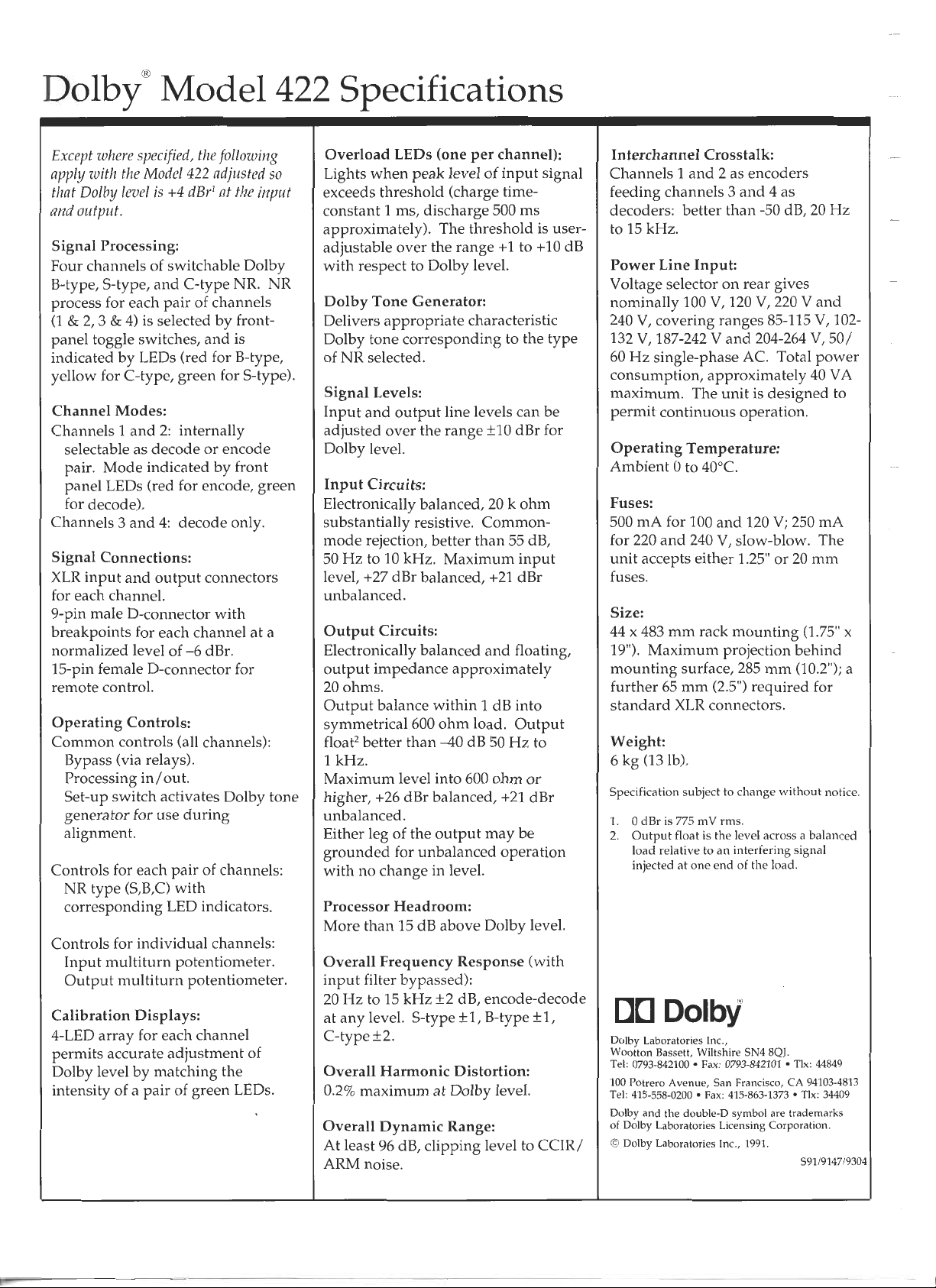
Page 1
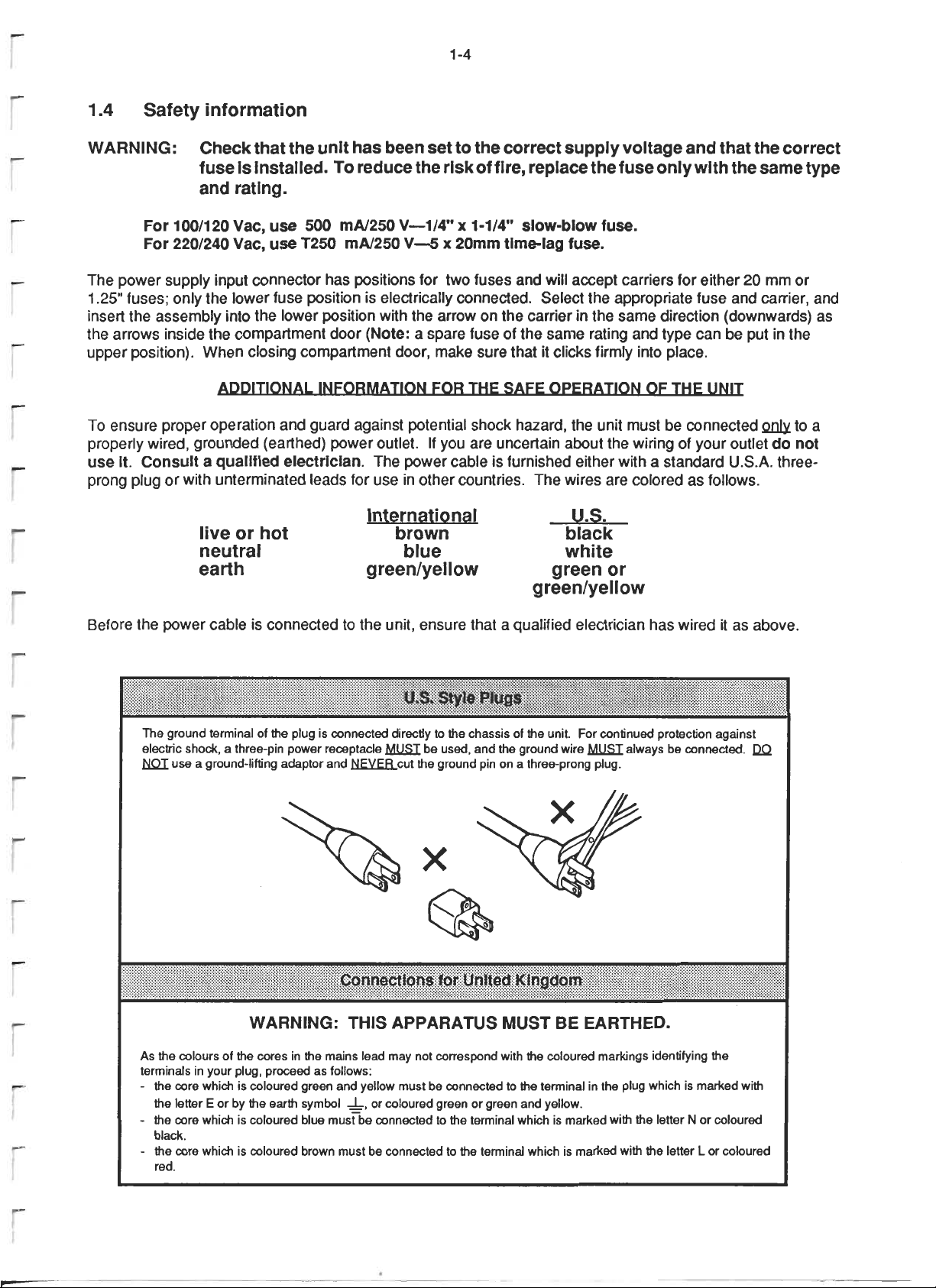
Page 2
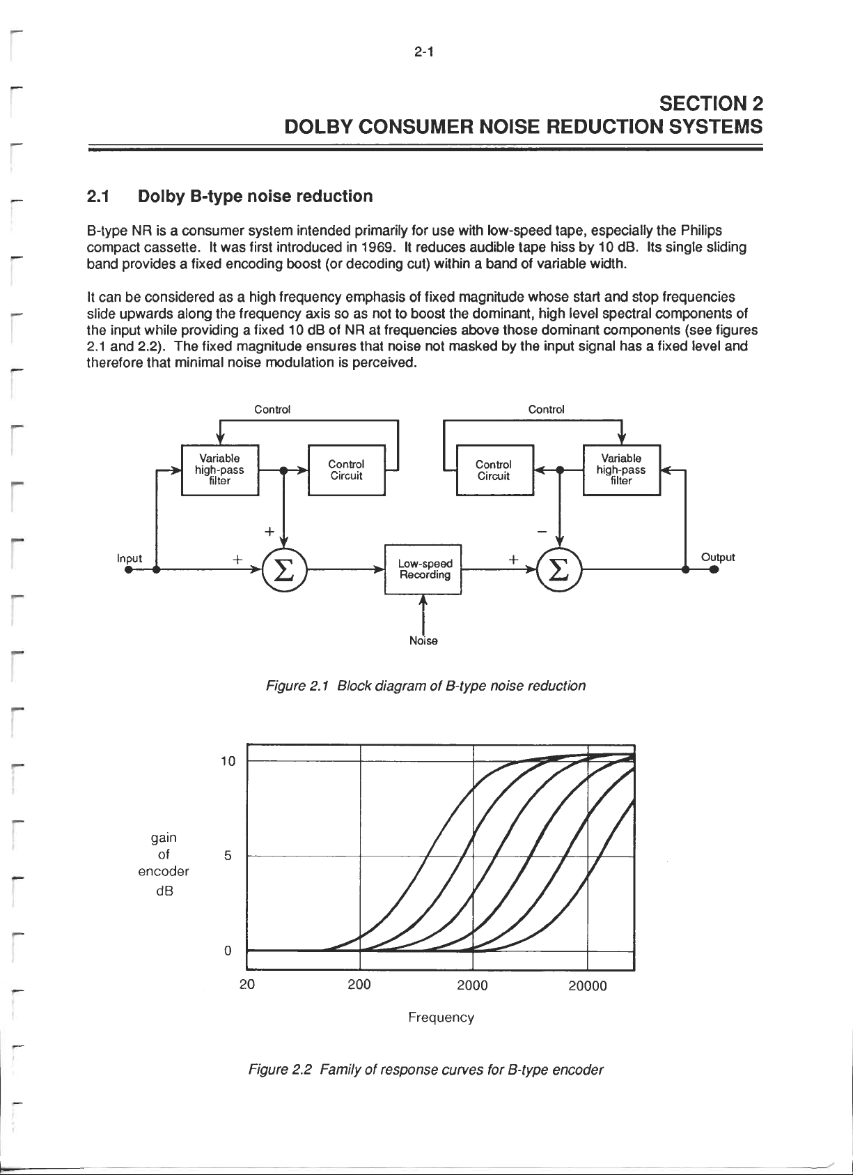
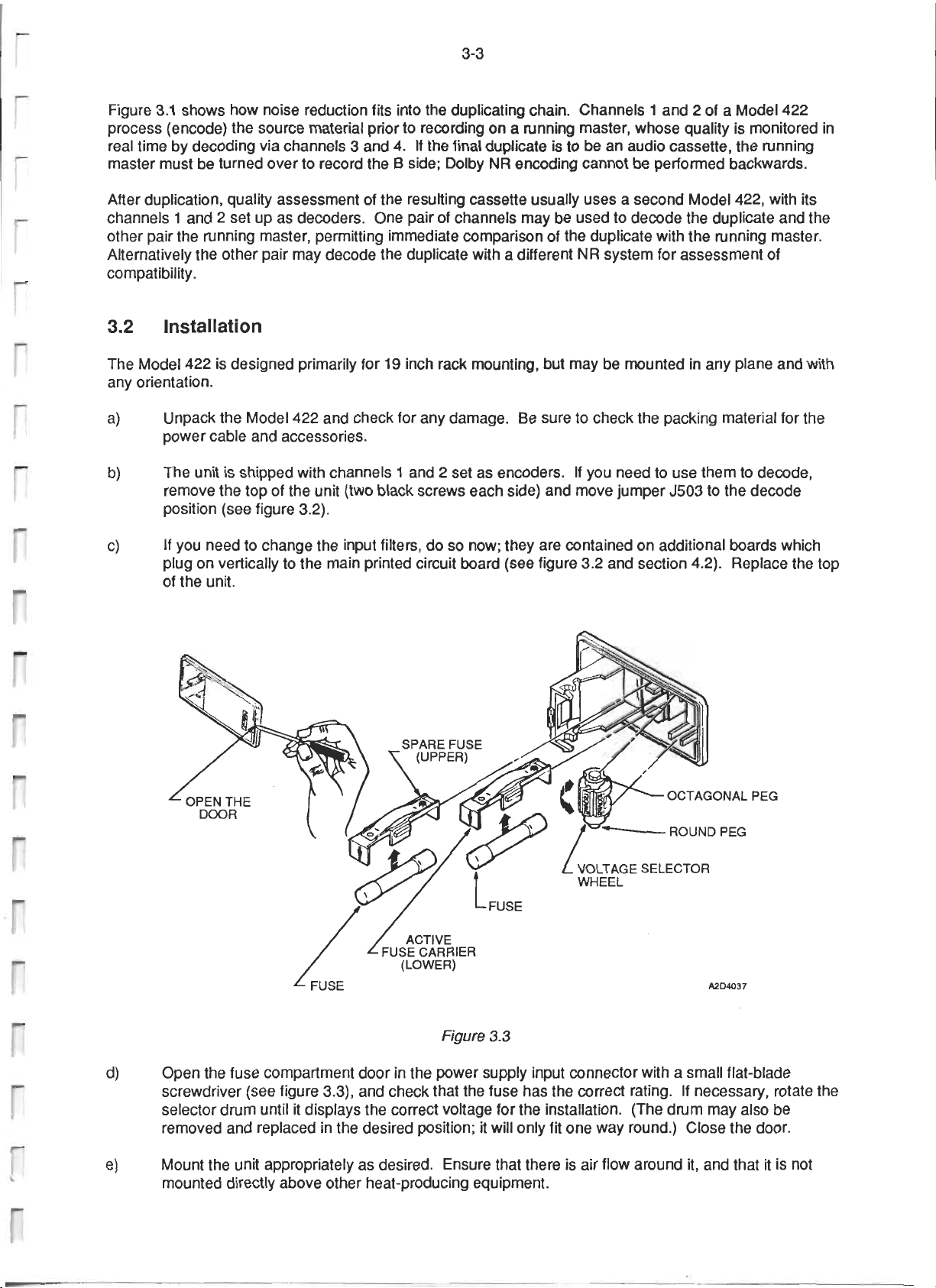
Page 3
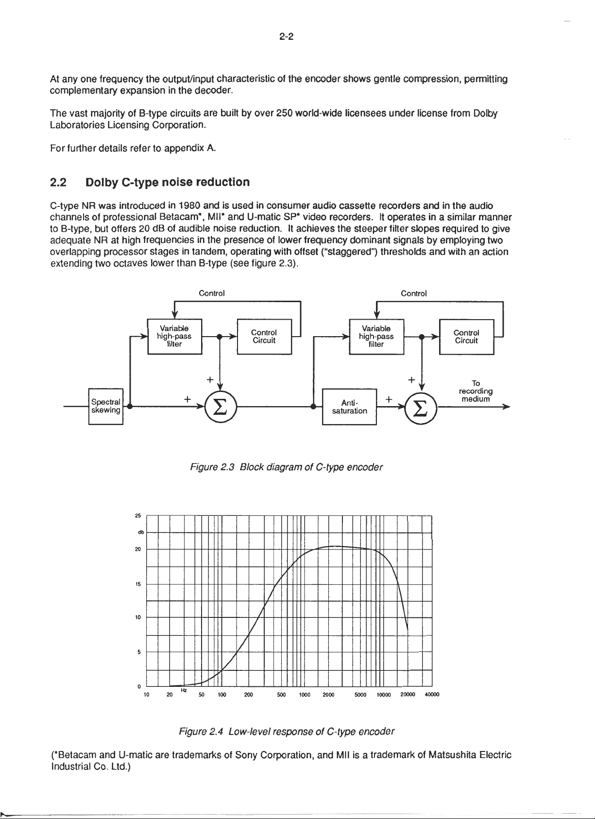
Page 4
Page 5

Page 6
Page 7
Page 8

Page 9
Page 10
Page 11
Page 12
Page 13
Page 14
Page 15
Page 16
Page 17
Page 18
Page 19

Page 20
Page 21
Page 22
Page 23
Page 24
Page 25
Page 26
Page 27
Page 28
Page 29
Page 30

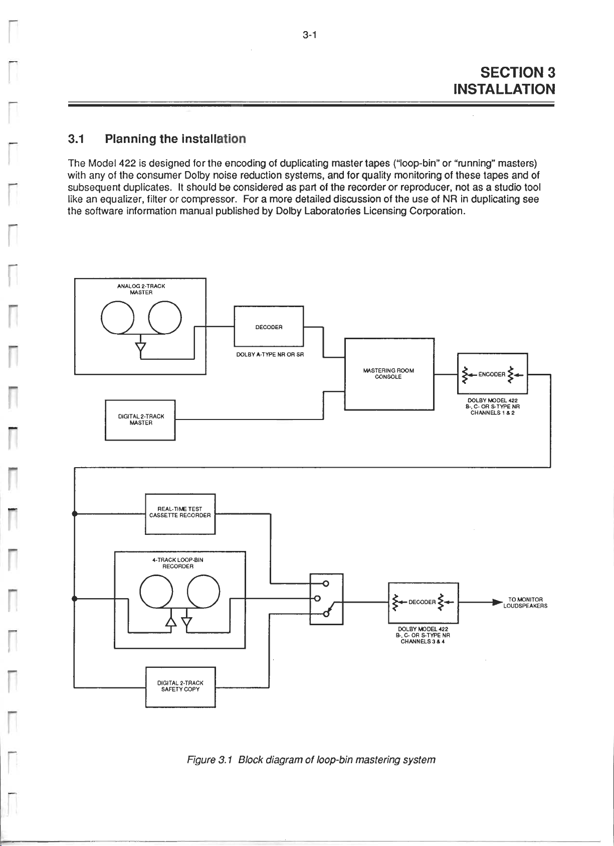
Page 31

Page 32

Page 33

Page 34

Page 35

Page 36

Page 37

Page 38

Page 39

Page 40

Page 41

Page 42

Page 43

Page 44

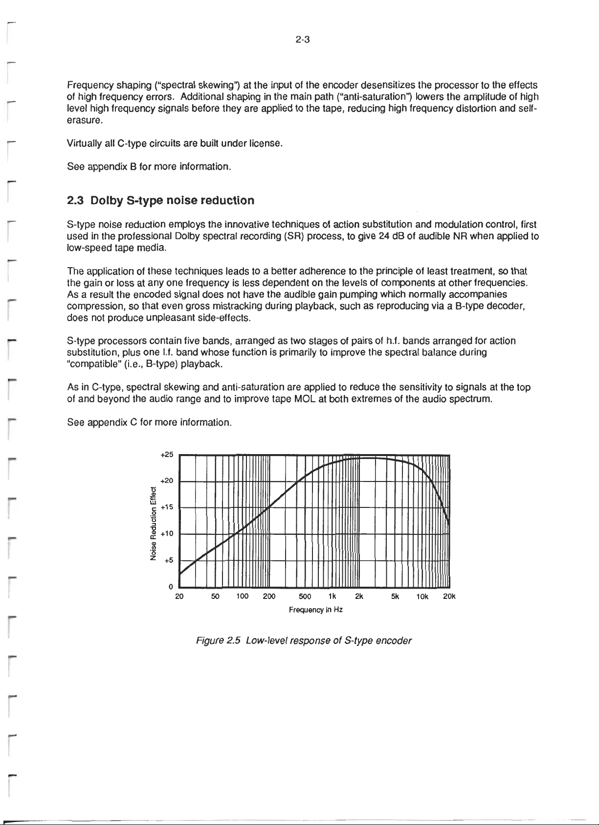
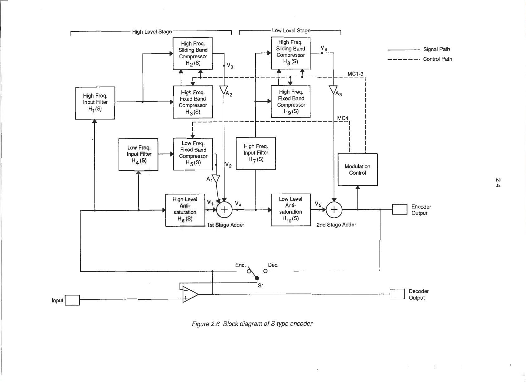
A 20 dB Audio.NoiseReductionSystem
for ConsumerApplications*
RAY DOLBY
Dolby Laboratories Inc., San Francisco and London
A 20 dB noise reduction system, designated C-type, for use in cassette tape recording
and similar applications is described. An arrangement of two compressors and two
expanders in cascade has been developed in which the signal-to-noise ratio improvement
is compounded without significant accompanying increases of the overall maximum
compression and expansion ratio. Overshoots, modulation distortion, and noise mod-
ulation are well controlled. The maximum demands made on transmission channel
uniformity are generally unchanged from those associated with the B-type system,
although the uniformity requirements extend over a greater range of signal frequencies
and levels. An improvement has been made in one condition of compressor/expander
mistracking, namely, low-level mid-frequency signals in combination with dominant
signals in the region above 10 kHz and incorrect channel response at such frequencies.
A further development reduces the tendency of highly equalized channels to saturate,
thereby increasing the useful signal levels which can be handled.
PAPERS
0 INTRODUCTION tape formulations and oxide thicknesses that had to be
created, since there was no practical possibility for the
The B-type noise reduction system [1], [2] was de- industry to use standard thick-oxide V4-in (6.3 mm)
veloped in 1967-1968 and first applied to open-reel
recording (KLH models 40 and 41). However, by this tape in cassettes (as there had been in 8-track cartridges).
time there was a general feeling that a more convenient available cassette recorders and cassette tapes, and by
tape format was required for widespread use. In late
1968 we therefore began experimenting with 8-track
cartridges and the B-type system. The results were en-
couraging if suitable tape formulations and oxide
thicknesses were used, but ergonomic and aesthetic
considerations persuaded us that the 8-track cartridge duplication firms. There was general agreement that
would not be a success as a quality recording medium; this was a promising development; under good con-
anyone willing to tolerate an endless-loop format would ditions it was possible to produce overall results that
be unlikely to be very interested in sound quality.
In early 1969 we turned to the Philips Compact Cas- has since been adopted and widely used, and by this
sette, which was another of several tape formats com-
peting for the popular market at that time. The Compact main technical defects of disks and B-type encoded
Cassette offered the advantage of rapid access, which
appeared to be a requirement for acceptance by critical conditions:
listeners. The disadvantage of very low tape speed (17/8
in/s, 4.75 cra/s) was to some extent offset by the special Disks Cassettes
* Presented at the 70th Convention of the Audio Engineering Ticks and pops
Society, New York, 1981 October 31-November 2.
98 d.AudioEng,Soc.,Vol.31,No.3,1983March
Throughout 1969 we researched the properties of
the end of that year we had adapted and improved several
cassette decks to provide wide frequency response,
low distortion performance with high stability. Using
the B-type noise reduction system, we demonstrated
our results to cassette deck manufacturers and cassette
were comparable with the best disks. The technology
time it is possible to draw up a comparative list of the
cassettes when produced and reproduced under the best
Mold-grain noise Hiss
Hiss High-frequencyoverloaddistortion
Page 45

PAPERS A20dBAUDIONOISEREDUCTIONSYSTEM
The low-frequency mold-grain noises (rumbling and maximum level, provided a good margin of safety in
rushing sounds) produced by disks are evidently un- solving the problem of suppressing compressor over-
noticed by most listeners; perhaps these noises are shoots without introducing audible distortions caused
masked by the ambient noises of typical listening en- by rapid modulation of the signal. In the development
vironments. Disk processing hiss is variable but usually of the B-type system in 1967-1969 these facts, coupled
not too obtrusive. The main audible defect of most with tests to determine the maximum dynamic action
disks is low-level ticks and pops. In contrast, cassette likely to be allowable for reasonable compatibility when
tapes have no audible rumble or other low-frequency encoded recordings were reproduced without decoding,
noises, and, of course, there are no ticks and pops. established the maximum noise reduction at 10 dB.
However, the hiss level is audibly greater than that of In the development of the C-type system in 1980,
disks; the continuing presence of this hiss has evidently the compressor overshoot and modulation distortion
been the main factor in causing the cassette to fall just consideration pointed strongly toward the retention of
short of disks in the estimation of quality conscious the dual-path 10 dB low-level format which had proved
listeners. A further element is that cassette tapes, es- to be successful in the A-type and B-type systems.
pecially the ordinary formulations used in mass du- While it was tempting to contemplate stretching the
plication, do not have the high-level high-frequency capability of the basic 10 dB circuit to performance
recording capability of disks. For economic reasons, levels in the 15-20 dB region, only a few experiments
most duplicators are reluctant to use tapes that might were enough to reconfirm that such an approach would
overcome this problem, be hazardous at best; it would be better to accept the
In 1978 we developed a system, HX (headroom ex- cost penalty of a more complex method and to be safe.
tension), to improve the high-level high-frequency A two-band configuration would not be much help,
performance of normal cassette tapes [3]. This system since each band would still be required to operate with
was introduced in consumer cassette recorders in 1979- the full dynamic effect. However, if two stages could
1980. While this development was welcomed by the be cascaded, then the stage gains and resultant com-
technical community, there was still a feeling that the pression and expansion would be multiplied (or added
basic noise performance of the cassette, using the B- on a dB basis) to yield an overall noise reduction of,
type noise reduction system, was inadequate. Several say, 20 dB. While early tests indicated that this was
different noise reduction systems offering more than an attractive method under ideal conditions, the resulting
10 dB of noise reduction became available, and many high compression ratios (up to 4:1) would clearly be a
cassette deck manufacturers requested a response from problem with the production and operating tolerances
· us to this activity, of practical cassette recorders. A method was therefore
Until early 1980 the author remained unconvinced devised whereby the dynamic actions of the two stages
that the underlying demand for an improved (and more could be spread out or staggered into different level
costly) system would be sufficient to justify the industry regions. Such dynamic action staggering, in which one
infrastructure required to support a new high-perform- stage operates at levels comparable with those of the
ance standard. However, performance expectations do B-type circuit, and the second stage treats signals some
not appear to diminish. Thus a new noise reduction 20 dB lower in level, is possible with compressor and
system called C-type has been developed, which, it is expander stages having a certain type of transfer char-
hoped, will meet a reasonable proportion of these ex- acteristic which will be discussed. This staggering
pectations. The author, as well as many others, will technique proved to be a key element in the development
be waiting with interest to see whether the long-term of the C-type system.
demand is broadly based enough to result in a significant Referring to Fig. 1, the A-type and B-type noise re-
change in usage patterns, duction systems employ a level transfer characteristic
This paper describes the new system, which utilizes which at any particular frequency comprises the fol-
two series-connected sliding-band compressor and ex- lowing elements:
pander stages, operating at different levels, to solve 1) A Iow-level linear portion up to a threshold (where
the problem of increasing the overall compression, ex- "linear" in this context denotes constant gain with
pansion, and noise reduction without introducing side changing input level).
effects. Further developments reduce high-frequency 2) An intermediate-level non-linear portion (chang-
tape saturation and improve the tolerance of the system lng gain with changing input level) above the threshold
to irregular response of the recorder at very high fre- and up to a finishing point, providing a certain maximum
quencies. Good frequency response and level reliability compression or expansion ratio.
are nonetheless required at lower frequencies. 3) A high-level linear portion having a gain different
from the gain of the low-level portion.
1 STAGGERED ACTION DUAL-LEVEL FORMAT
This type of characteristic can be designated a bilinear
characteristic because there are two portions of sub-
In the development of the A-type noise reduction stantially constant gain. Such characteristics may be
system in 1965-1966 [4] the author found that a two- distinguished from other types of characteristics,
path configuration and a maximum dynamic action of namely:
the order of 10 dB, placed some 30 dB below the nominal 1) A logarithmic or nonlinear characteristic with
J. Audio Eng. Soc., VoL 31, No. 3, 1983 March 99
Page 46

DOLBY PAPERS
either a fixed or a changing slope and with no linear connection shows that they not only have the previously
portion: the gain changes over the whole dynamic range, discussed advantages but further ones as well, namely,
2) A characteristic having two or more portions of a way of solving the high compression ratio problem
which only one portion is linear, and a way of dealing with the larger overshoots which
An advantage of a bilinear characteristic is that the accompany greater overall compression.
threshold can be set above .the input noise level or Note that the superposition of the high- and low-
transmission-channel noise level in order to exclude level linear regions does not increase the compression
the possibility of control of the circuit by noise; the ratio in these regions (since by definition the compres-
low-level region is a reliable "gain floor," which con- sion ratio is 1). The compression ratio is increased
tributes to overall stability of the signal. The high- only in the limited region in which dynamic action
level portion of substantially constant gain avoids the takes place. Therefore it becomes possible to separate
nonlinear treatment of high-level signals which would the areas of dynamic action of the two stages in such
otherwise introduce distortion, either by rapid modu- a way as to obtain the required overall increase in com-
lation of the signal or by overshoots and subsequent pression without altering the overall maximum
clipping. In the region of dynamic action, at inter- compression or expansion ratio significantly. A further
mediate levels, relatively long attack and recovery times feature is that the overall result is bilinear, with all of
are used in order to reduce modulation distortion. The the attendant advantages. Thus the action staggering
attack and recovery times are progressively reduced possibility of bilinear compressors and expanders rep-
with increasing amplitude steps, the high-level portion resents a further advantage of this type of device.
providing a region within which to deal with the over- At any given frequency, the thresholds and dynamic
shoots, which in a dual-path system are suppressed by regions of the compressor or expander stages are set
clipping diodes acting upon the noise reduction signal to different values so as to stagger the intermediate-
only. levelportionsofthe characteristicsofthestages.This
Thus with 10 dB of dynamic action spread over an results in a change of gain over a wider range of in-
input signal level range of about 20-25 dB, so that the termediate input levels than for each of the stages in-
maximum compression ratio does not substantially ex- dividually, an increased difference between the gains
ceed 2:1, it is possible to set the threshold at a level at low and high input levels, and a maximum compres-
high enough to be well clear of input signal noise and sion or expansion ratio which is substantially no greater
recorder noise, that is, in the region of 40 dB below than the maximum compression ratio of any single stage.
the nominal peak level. This leaves a high-level linear The thresholds of the overshoot suppressors are also
region of some 20 dB for the suppression of overshoots, staggered along with the stagger of the syllabic thresh- '
Note that bilinear compressors and expanders de- olds. The overshoots of the low-level stage are cor-
termine the two end regions of constant gain by means respondingly reduced.
of fixed, preset circuit elements, such as resistors and Fig. 2 shows the basic block diagram of the staggered
capacitors, which are inherently stable and cannot cause action method. A high-level bilinear compressor feeds
dynamic errors, waveform distortions, and the like.
Only in the transitional area can any dynamically active
portions of the circuits introduce signal errors. ._
In contemplating the possibility of a multistage cir-
cuit,it shouldbenotedthatpriorattemptshaveresulted ,,%
in a multiplication of the maximum compression ratios
of the individual stages with the consequence of an -_0 INPUT(dB) ,,,X_.d3_
overall high compression ratio, which is not very useful i ,.q,'Yl
in a practical noise reduction system (for example, one
circuit with a compression ratio of 2:1 and the other _ "--FINISHPOINT
with a compression ratio of 3:1 will yield an overall DYNAMICACTION
_x,3,fv
2't
ratio of 6:1). Other cascaded approaches have utilized COMPR[S$ION F_j//_ 00TPUI(dB)
compressorstages operating in mutuallyexclusive fre- _/
quency ranges. While such an arrangement may not THRF_5140LD
compression ratio over that of a single stage, it cannot
provide an overall increase of noise reduction at a par-
necessarily result in any increase in the maximum q_?_,xX// EXPANSi0 N
ticularfrequency. ,,?q)'%
Experience has shown that with a compression ratio
of much more than 2:1 it becomes increasingly difficult ,,_"
to ensure complementarity between the compressor and
theexpander;in particular,levelerrorsorerrorsinthe -60
frequency response of the recorder lead to correspond-
ingly multiplied errors at the output of the expander.
An examination of bilinear circuits used in a series Fig. 1. Bilinear compression and expansion characteristics.
100 J. Audio Eng. Soc., Vol. 31, No. 3, 1983 March
.Ax,
..X,x
///
7
Page 47

PAPERS A 20 dB AUDIO NOISE REDUCTION SYSTEM
the low-level bilinear compressor connected in series, level stage modifies the input signal to the low-level
During playback a pair of series-connected bilinear stage as a function of'signal level. The overall char-
expanders receives the input from the signal channel acteristic produced is the left-hand portion of curve 1,
and provides an overall noise reduction system output the section from la to 2a, and the right-hand portion
at the output of the high-level expander, of curve 2. Analogous considerations apply in the case
For overall complementarity of the system, the order of the expanders depicted on the lower half of the figure.
of the stages in the compressor is reversed in the ex- Thus even with two compressors or expanders in
pander. Thus the last stage of the expander is comple- series, the end regions of operation still remain fixed,
mentary to the first stage of the compressor (and likewise the maximum compression and the maximum expansion
the first stage of the expander to the last stage of the ratios are not increased beyond those of single devices,
compressor) in all respects, both steady state and time and the advantages of single bilinear devices are re-
dependent, tained. Consequently,the maximumerror inlevel oc-
The separation or staggering of the high- and low- cutting within the range of dynamic action caused by
level stages is depicted in Fig. 3, which plots compres- the devices in series should not substantially exceed
sion ratio versus input amplitude (horizontal axis) for the maximum error of a single device. With the con-
the compressor or expander stages operating at a par- tinually changing levels of real signals, however, the
ticular frequency. The top curves are those of corn- time-probability of a level error is increased because
pressors, the bottom curves those of expanders. In this of the greater range of dynamic action of the cascaded
example the areas of action as a function of input level devices over that of a single device.
are separated such that the product of the two curves Note that in the representation of Fig. 3 the dynamic
results in an overall characteristic having a compression action of a logarithmic compressor or expander becomes
ratio or expansion ratio which does not exceed 2:1 a horizontal line; line 3, for example, is the characteristic
(1:2) between the two maximum compression points of a 2:1 compressor, and line 4 is that of a 1:2 expander.
la and 2a (lb and 2b) of the two devices. For clarity, It is clear that there is no opportunity for separating or
the curves are shown in idealized form; as a practical staggering the actions of such devices.
matter the curves may be somewhat asymmetrical. The To obtain a first-order approximation of the parameter
compressor portion of curve 2 represents the variations relationships in action staggering, it is useful to idealize
of the compression ratio of the high-level stage as a Fig. 3 even further. Assume that each compressor (and
function of the input level to the high-level stage, while expander) immediately reaches its maximum compres_
the compressor portion of curve 1 is the variation of sion ratio at a threshold level and holds that ratio until
the compression ratio of the low-level stage as a function it reaches a finishing point at a higher level where its
of the input level to the high-level stage, as if the high- dynamic action abruptly stops.
level stage had a constant gain. In practice, the high- Based on observations of the resulting transfer char-
INPUT --- BILINEAR --- BILINEAR _( BILINEAR BILINEAR --'-OUTPUT
COMPRESSOR COMPRESSOR EXPANDER EXPANDER
Fig. 2. Basic block diagram of staggered-action bilinear noise reduction system.
t
cz:
OVERALLCI4ARACTERISTIC
2:1 /" MAXIMUM
-_ I LEVEL
1:2 t,,.4 _lb k-Zb EXPANSIONRATIO
><
J. Audio Eng. Soc., vol.31, No. 3, 1983 March 101
F3 ira 2a
Fig. 3. Action-staggering principle.
COMPRESSIONRATIO
INPUT
Page 48

DOLBY PAPERS
acteristics (Fig. 4), the following equation sets forth in improved noise modulation performance of the low-
the relationship between threshold level T, finishing level stage; there is little virtue in keeping the two
point F, compression ratio C, and gain G of the stages: areas well separated.
The two stages of the C-type system are each of the
T = F CG (1) sliding band type, similar to that of the B-type circuit
C - 1 ' [1], [2]. The first stage of the compressor is set for op-
Using this equation is straightforward for the first eration at levels similar to that of the B-type circuit,
stage. For the second stage, the first-stage threshold and the second stage is set for operation at lower levels.
becomes the second-stage finishing point. However,
In this order there is a useful interaction between the
the calculated threshold is the overall threshold, referred stage gains and the areas of dynamic action; the area
to the first-stage input. To obtain the threshold of the
of action of the downstream stage is partly determined
second stage referred to its own input, the low-level by the signal gain of the preceding stage. Thus with
signal gain of the first stage is taken into account. The
10 dB of low-level gain per stage, the control amplifier
equation can also be arranged to give the finishing point gain requirement of the second stage is reduced by 10
F, the compression ratio C, or the gain G.
dB. When a high-level signal appears, the i0 dB gain
Consideration of the above equation and Fig. 4 shows of the first stage is eliminated from the overall effective
that for the case of a 2:1 compression ratio, half of the amplification used to derive the control signal of the
threshold staggering is provided by the signal gain of
the first stage and the other half must be provided by
the control circuitry of the second stage.
second stage. This improves the noise modulation per-
formance of the second-stage sliding band.
If the arrangement were reversed, with the low-level
As previously mentioned, a 2:1 compression ratio stage first, there would be reduced interaction. The
appears to be about the maximum that can be used in control amplifier of the first stage would need a high
cassette recording systems, because of error amplifi- gain in order to achieve the required low threshold.
cation effects during decoding. A lower compression
ratio (such as 1.5:1) would permit an expander to track
the compressor more easily, but on the other hand, the
This high gain and low threshold would then apply
even in the presence of high-level signals, which in
the case of a sliding band system would result in poorer
dynamic action would have to extend down to lower noise modulation performance. Thus the arrangement
levels, resulting in greater susceptibility to noise mod- actually used takes best advantage of the prevailing
ulation for a given maximum amount of noise reduction, signal gains of the individual stages, namely:
Hence there is a trade-off between undesirable effects 1) Under very low level (sub-threshold) signal con-
caused by both high and low compression ratios.
Similar considerations apply in arranging the stag-
gering of a dual-stage system. Once the maximum al-
ditions the control amplifier gain requirement of the
second stage is reduced by 10 dB over what would
otherwise be required to achieve the desired staggering.
lowable compression ratio has been decided, then it is 2) A signal-dependent variable threshold effect is
best to employ the minimum amount of staggering con- achieved, which with sliding band stages reduces noise
sistent with keeping the overall ratio within the design modulation effects.
goal. Squeezing the area of dynamic action of the low-
level stage up close to that of the high-level stage results 2 NOISE-REDUCTION CHARACTERISTIC
The maximum amount of compression and expansion
.8o -7o -6o -so -4o -3o -zo -to J to be used in the C-type system was more or less ar-
t I t t t _ t '0 bitrarily set at 20 dB. This seemed a natural goal, neither
INPUT J
d8 _ too little nor too ambitious, moreover offering the pos-
'N_'5 -to sibility of adapting existing B-type integrated circuits_,._. C_ before dedicated C-type integrated circuits would be-
C2
termine an optimal spectraldistribution of the noise
--30 reduction. If the frequencies to be treated were restricted
t' to as narrow a range as possible, compatibility would
' J''___i'"'_../_ --z0 come available Nevertheless, it was necessary to de-
--40 be improved, noise-modulation performance enhanced,
and there would be fewer troubles caused by recorder
0trr_'r response irregularities at the frequency extremes.
dB -so In connection with the development of the B-type
system, beginning in 1967, listening tests were made
C0MP .-t0 to determine what range of frequencies had to be treated
to bring the noise of 33/4-in/s (9.5-em/s) open-reel re-
.-70 cording into subjective spectral balance using moderate
Fig. 4. Idealized construction to show parameter relationships to high listening levels, such that the tape hiss, with
(Eq. 1), C--compression ratio; T_threshold; F--finishing noise reduction, was discernible but not excessive. Thus
point; G--stage gain. the high-pass filter cutoff frequency used in the B-type
102 J. Audio Eng. Soc., VoL 31, No. 3, 1983 March
Page 49

PAPERS A20dBAUDIONOISEREDUCTIONSYSTEM
circuit was set at 1.5 kHz. This cutoff frequency was quency the audible noise, relative to noise at higher
retained in adapting the circuit for use with cassettes frequencies, is negligible with C-type noise reduction
in 1969, although the filter configuration was changed switched in, from either the amplifier or the tape.
to provide more noise reduction in the 300 Hz to 1.5
kHz range, as well as improved noise modulation per- 3 SPECTRAL CHARACTERISTIC--HIGH
formance. FREQUENCIES
The same kinds of listening tests were made in the
development of the C-type system, using high-quality characteristics of the system, attention was also directed
Type II cassette tape, 70 txs equalization, a quiet res-
idential listening environment, and volume settings ation of the shape of the CCIR noise-weighting char-
corresponding to rather loud listening conditions; that
is, as in the B-type tests, the volume was set such that
tape noise with noise reduction was perceptible but not
annoying. Many filter configurations and combinations
were tried; in the early stages of the development it
During the tests to determine the low-frequency
to the high-frequency end of the spectrum. Consider-
acteristic (Fig. 5), which was established for wide-
band, relatively low noise audio systems, shows that
there is a significantly reduced need for noise reduction
at extremely high frequencies (above about 10 kHz).
Cassette tape recording has problems with record/
had been hoped that one of the two stages could be left playback frequency-response reliability and tape sat-
as a standard B-type circuit, for easy switchable cum- uration in this frequency region. Moreover, with certain
patibility between B-type and C-type operation. How-
kinds of signals, compressor/expander tracking accuracy
ever, the spectral distribution tests eventually proved is affected. It seemed that the introduction of a new
that this placed too heavy a burden on the second stage; noise reduction system could be used as an opportunity
it was required to produce substantially more than l0
dB of noise reduction in the several hundred hertz to
2 kHz region. The solution to this problem was to
to optimize the overall performance of the cassette
medium, including the noise reduction system, using
the above facts.
abandon the attempt to retain one stage as a standard
B-type circuit; both circuits had to be nonstandard.
3.1 The Midband Modulation Effect
Unfortunately, this approach increased the switching
and component complexity, but it yielded a system in Compressor/expander complementarity requires not
which the dynamic action burdens are more evenly only that the expander have the inverse characteristics
shared between the two stages. The listening tests ul- of the compressor, but also that the transmission channel
timately set the filter cutoff frequencies of the two cir- between the compressor and the expander preserve rel-
cults equal, at two octaves below that of the B-type ative signal amplitudes, and preferably also phases, at
circuit, namely at 375 Hz. all frequencies within the bandwidth of the signals cum-
The use of equal cutoff frequencies yields a full pressed. As received by the expander, changes in level
compounding of the frequency discriminations of the caused by the transmission channel are indistinguishable
two circuits, giving a steeply rising overall character- from signal processing by the compressor. The resulting
istic. This results in leaving the low-frequency region, errors in the expanded signals can be significant and
in which little treatment is necessary, essentially un- audible, depending on the spectral content of the signals.
touched while providing substantially the full amount With the sliding band B-type system, the most audible
of noise reduction above about 500 Hz. The resulting error is not the direct effect on very-high-frequency signals
noise reduction begins at about 100 Hz (3 dB), is about themselves, but rather the modulation effect on mid-fie-
8 dB at 200 Hz, 16 dB at 500 Hz, and is essentially quency signals, such as in the several hundred hertz region.
20 dB above about I kHz. This characteristic was de- For discussion purposes, this effect will be referred to
termined using several types and qualities of loud- as the midband modulation effect.
speakers and headphones, with both daytime listening In wideband companders an amplitude error at the
and late night listening, when the ambient noise level controlling frequency will manifest itself to the same
(in San Francisco) is significantly reduced.
The cassette recorders used in the tests were standard +to
productionmodelsselectedfor low humlevels. The -_
selectionprocessrevealed suchwidevariationsinhum 0 J
level and characterthat only the best recorderswere J
used in the final tests, so that hum reduction would not qo ._
be a factor in determining the noise reductionchar- J
acteristic. It was abundantly clear that it is possible to dB
/
design recorders whichare free of audiblehum; a spec- J
ification simply had to be established for allowable _30 /
levels for the power line fundamental and each of its /
harmonics. Thus the shape of the low-level noise re- _40 ,-"
duction characteristic-was set only on tape noise con- z0 50 f00 200 s00 _k zk $k _0k Z0_
siderations; with good head preamplifiers, tape noise Hz
predominates down to about 200 Hz. Below this fre- Fig. 5. CCIR noise-weighting characteristic (CCIR/ARM).
J.AudioEng.Soc.,Vol.31,No.3,1983March 103
Page 50

DOLBY PAPERS
degree in all other portions of the spectrum; this may rather surprising in its simplicity, and is termed spectral
or may not be acceptable. In sliding band companders skewing. Advantage is taken of the fact that the high-
(B-type and C-type) an error at a dominant high fre- frequency signals which cause the problem are usually
quency is substantially multiplied at mid-frequencies, complex in nature; that is, they occupy a relatively
(Conversely, if the controlling frequencies are at mid- broad band of frequencies and are not at single discrete
frequencies_ as they usually are, then any errors at the frequencies. The method used is to subject the signals
high-frequency extreme are reduced; this is an advantage to be processed by the compressor to an abrupt high-
of sliding band companders.) The midband modulation frequency drop-off which is within the useful bandpass
effect is rare with normal music sources; it may, for of the system but somewhat below the frequency at
example, be audible with intermittent high-level high- which the record/playback response becomes highly
frequency signals such as brushed cymbals in combi- unreliable. A corner frequency of 10-12 kHz fulfills
nation with a more or less continuous low-level mid- these conditions. In this way the distributions of th'e
frequency sound, such as background violins. In such signals processed by the compressor are altered or
a case, the violins may be modulated in amplitude, skewed such that the compressor action is significantly
even after decoding, because the cymbals cause the less susceptible to the influence of signals beyond the
encoder band to slide without a complementary sliding abrupt roll-off frequency. Signals processed by the ex-
of the decoder band. This effect is basically a frequency pander are subjected to a complementary boost so that
response error effect, as opposed to a tape saturation an overall flat frequency response is maintained. The
effect; it might be caused by inaccurate biasing and spectral skewing network is situated at the compressor
equalization or by gap loss, poor azimuth, and the like. input; the de-skewing network, with complementary
However, the effect will be worse if there is also sat- characteristics, is located at the expander output.
uration in the controlling frequency region. The spectral skewing principle as applied to sliding
Reduction of the midband modulation effect is one band companders can best be understood by reference
reason for the incorporation of sharp low-pass filters, to Fig. 6. Fig. 6(a) shows the spectrum of a signal that
popularly known as multiplex (MPX) filters, in audio might provoke the midband modulation effect (such a
products using the B-type noise reduction system. Such signal might be generated by a wideband percussive
band-limitation filters have corner frequencies at the sound). The compressor control circuit preemphasis
edge of the useful bandpass of the system (about 16 results in an energy spectrum as shown in Fig. 6(b).
kHz) in order to avoid limiting the system bandwidth After rectification, the peak in the preemphasized ac
unduly. Such filters have several functions: control signal spectrum provides the dc signal that
1) Attenuation of subcarrier components and the 19 controls the sliding band action of the compressor.
kHz pilot tone used in FM broadcasting, in order to Fig. 6(c) illustrates the different frequency responses
avoid bias "birdie" beats (whistles), impairment of of four tape recorder channels, a, b, c, and d. The
the noise-reduction action, and encoder/decoder mis- effect on the spectrum of Fig. 6(a) is to cause four
tracking, differentspectra[Fig.6(d)]tobe presentinthecontrol
2) Attenuation of tape recorder bias which may leak circuit of the expander, resulting in the four dc control
into the signal circuits, in order to avoid encoder/decoder signals shown; clearly, errors in decoding will result.
mistracking. An idealized spectral skewingcharacteristic [Fig.
3) Attenuation of supersonic signal components or 6(e)] causes the compressor and expander to generate
of spurious radio frequency components in the encoder the same dc control signal in each case, as shown in
input signal which may otherwise result in audible in- Fig. 6(f), which results in accurate decoding not only
termodulation products and/or bias birdies, of the high-frequency signals, but also of any other
4) Attenuation of supersonic tape noise or other signals at lower frequencies. Note that the network
transmission channel noise at the decoder input, in does not eliminate the sliding of the frequency band.
order to avoid encoder/decoder mistracking. Indeed, it may be only slightly reduced. However, the
5) A signal bandwidth definition to promote corn- sliding now becomes recoverable during playback.
plementarity of the encoder/decoder--that is, to reduce The spectral skewing characteristic used in the C-
the midband modulation effect, type system has a simpler and more economical form
Strictly speaking, if an ideal channel exists between than the idealized curve of Fig. 6(e). A 12 dB notch
the encoder and the decoder, then the input filter to the characteristic is formed by combining the input and
decoder should be disconnected, as its inclusion the- output signals of a resonant notch filter with a center
oretically results in a slight noncomplementarity (the frequency of 20 kHz and a Q of 1. The resultant char-
encoder signal is subjected to one stage of filtering, acteristic within the audio band can be seen in Fig. 7.
the decoder to two). However, removal of the decoder Compare this with Fig. 8, which shows representative
input filter must be done with caution because of the measured high-frequency response curves for several
considerations listed above, typical cassette recorders. These curves show that, for
levels below saturation, the typical recorder in good
3.2 Spectral Skewing adjustment has little deficiency in response below 10-
20 kHz. Hence, at most levels the spectral skewing
The solution to the midband modulation problem is network will ensure that there will be a significantly
104 J. Audio Eng. Soc., Vol. 31, No. 3, 1983 March
Page 51

PAPERS A20dBAUDIONOISEREDUCTIONSYSTEM
DC
' I, I I ! I .... I !
5 8 lO 15 20 kNZ lO IS 20 kHZ
1C_m- )C.._
(a) (b)
Fig. 6(a). Representation of spectral distribution of signal Fig. 6(b). The signal of (a) after control amplifier preemphasis
having a significant wideband component, in the compressor.
d Dc CO_TI_.
0 tX _
ua
.,.a _{}
I I I I
i _ _ SIGNAL
g
_.-e,. I0 15 20 kl.lz _._,,? fs 20 KHz
(c) (d)
Fig. 6(c). Four different tape recorder frequency responses Fig. 6(d). The signal of (a) compressed and then sent through
(a,b, c, d). recorderchannelsa, b, c, d, resultingintheabovesignal
distributions at the point of rectification in the expander;
different dc control signals a, b, c, d are thereby produced.
-- SIGNALLEV
0
-- SPECTRALSKEWING
'-' -I0
V c_A_Acrc_sTJC
t '"1 I _ I I' I
't -'4- I0 IS 20 KNZ ._.._ I0 IS lO P(14z
(e) (f)
Fig. 6(e). Idealized spectral skewing characteristic. Fig. 6(f). As (d), but with spectral skewing treatment at the
input of the compressor; the same dc control signal is produced
in the expander with the four different recorder responses a,
b, c, d.
Fig. 6. Example showing how spectral skewing tends to desensitize the noise reduction system to recorder errors at very
high frequencies.
I _ { reduceddiscrepancy inthe decodercontrolsignal caused
SPECTRAL
SKEWING) I by uncertainties in response at extremely high fie-
r
..,.,_ [ _)I ANTISATURATION 0 quencies.
-""_'-hV/- _ The spectral de-skewing network used during de-
- SPECTRALI/_\SKEWii4Gff M _ coding results in about a 12 dB loss of noise reduction
+ANTISATURATION _/ _ in the 20 kHz region, leaving only about 8 dB of noise
v
-l0 -_ reduction. However, reference to the CCIR weighting
I _ curve (Fig. 5) shows that the frequencies above 10kHz
- I...-
g, are on the steeply declining portion of the curve; in
the 20 kHz region the ear is some 30 dB less sensitive
to noise than in the 5 kHz region; this fact makes the
to 5o too 2oo soo ,ooo2ooo smo ,ooooZ0k
-20 spectral skewing technique possible.
r_QUE_CV(,z) The reduced psychoacoustic need for maintaining
substantial noise reduction at frequencies above 10 kHz
Fig. 7. Spectral skewing and antisaturation characteristics
used in C-type system. Overall antisaturation effect is pro-
is the high-frequency counterpart of the ordinarily ob-
duced by combination of the two characteristics, served ability of the B-type noise reduction system to
J. Audio Eng. Soc,, Vol. 31, No. 3, 1983 March 105
Page 52

DOLBY PAPERS
provide a subjectively useful amount of noise reduction ration. Thus the network not only desensitizes the
even though the low frequencies are not treated at all. compressor to the frequency components likely to cause
Good engineering can eliminate hum, which, as men- trouble during decoding, but it also reduces the chance
tioned previously, is the only low-frequency noise which for recording deficiencies at those frequencies, cum-
is subjectively troublesome in cassette tape recording, pounding the advantage. The significant improvement
Note should be taken that the use of a spectral skewing observable in single-tone frequency response curves
network does not obviate or replace an overall band- is likely to be interpreted as the advantage of the tech-
limitation filter (MPX). As discussed, band-limitation nique; the improvement is easy to demonstrate graph-
filters used in both recording and PlaYback have several ically. The spectral skewing network, by itself, improves
functions in addition t° reducing the midband modu- the high-frequency saturation performance of cassette
lation effect. Therefore, even in the case of the highest tapes by several decibels in the 10-20 kHz region.
quality recorders, it is essential to have band-limitation However, cassette tapes suffer from saturation problems
filters and to use them. Cleaner, more accurate re- down to frequencies as low as 2 kHz. To accommodate
cordings will be the result. It may be noted, however, this it is not possible to increase the bandwidth of the
that when spectral skewing and de-skewing are em- spectral skewing notch, or to extend the effective cutoff
ployed, as in the C-type system, then the band-limitation frequency downwards significantly, for two reasons:
filters may have comparatively high cutoff frequencies 1) the noise reduction effect would be audibly impaired,
(such as 20 kHz), without provoking the midband and 2) the effectiveness of the spectral skewing network
modulation phenomenon (but a switchable 19 kHz notch in treating the midband modulation effect would be
should be provided for recording FM broadcasts), reduced. The CCIR weighting curve (Fig. 5) shows
that full noise reduction action must be maintained up
4 SATURATION REDUCTION to about 10 kHz. Moreover, the efficiency of the spectral
skewing action is dependent upon a relatively abrupt
Inspection of Fig. 8(d) shows that high-frequency characteristic [Fig. 6(e)]. On the other hand, at least
saturation is a serious problem in cassette recording, in approximately the 2-8 kHz frequency range, the
Usable peak levels at lower frequencies are some 8- saturation characteristics for typical cassette tapes are
10 dB higher than shown in this particular graph, with comparatively gradual, as can. be seen in Fig. 8(d) (0
an even further deterioration of performance at high dB curve).
frequencies. The above considerationspoint to the need for a
A useful by-product of the use of the spectral skewing different method of solving the saturation problem in
network is the reduction of very high frequency satu-
the mid-high-frequency area. A changed tape equali-
zation characteristic could be used, but this would have
a direct bearing on the overall noise level. An equalized
-ts -25 _.J' high-frequencylimiter could be employed, but this
treatment during decoding. Headroom extension [3] is
-30 -30- --
da a_ relevantbutalsohasthedrawbackof cost.
woutdbecostly andinadditionrequirecomplementary
The following antisaturation method, which is both
simple and effective, is incorporated into the C-type
noise reduction system. Note that in a dual-path com-
pressor or expander circuit the output at very low signal
levels is provided mostly by the noise reduction path.
Jo zo 2 s l0 z0 For 10 dB of dynamic action, the contributions of the
k_lz kHz
main and the noise reduction paths are in the ratios of
(a) (b) 1and2.16,respectively.Athighsignallevels theroles
the predominant signal component, and the further path
-z_ /_ contribution is negligible.
0ds The saturation-reduction method is based on the above
-30 \_v-c' observations; namely, an equalizer providing the re-
_.,,,,,q of the two paths are reversed: the main path provides
as dB \_! quired attenuation of high-frequency drive is placed in
_d8 At high signal levels essentially the full effect of the
_20 the main path of the compressor, as shown in Fig. 9.
equalization is obtained, with a consequent reduction
in high-frequency saturation. However, at low levels
5 _0 2o s _0 20 the equalization effect is reduced, since the contribution
kHz kHz
of the noise reduction path becomes significant, If, for
(c) (d) example,the antisaturationnetworkprovides for a 3
Fig. 8. Measured high-frequency responses of four typical dB attenuation at a particular frequency, then, ignoring
cassetterecorders, phase considerations, the low-level effect will be:
106 O.Audio Eng.Soc., Vol. 31, No. 3, 1983March
Page 53

PAPERS A20dBAUDIONOISEREDUCTIONSYSTEM
0.71 × 1 + 2.16 = 2.87 (9.2 dB) . 5 BLOCK DIAGRAM--C-TYPE CIRCUIT
That is, a 3 dB reduction in high level recording drive Based on the principles discussed, Fig. 10 shows
is obtained for a 0.8 dB loss in noise reduction effect, the basic block diagram of the C-type compressor and
It is necessary that a complementary correction be expander. The networks Nl and N 2 are the noise re-
provided on the playback side, so that the signal is duction side chains. The spectral skewing network is
restored. The type of correction required can be deduced placed at the input of the highrlevel stage of the corn:
from Fig. 9, whichshoWs a_syminetrical compressor pressor, thereby affecting the operation of both the
and expander configuration, including the placement high- and the low-level compressor stages. Note that
of networks in the main signal path. Let the input signal the de-skewing network, being situated at the output
to the compressor be x, the signal in the recorder channel of the whole system, has no effect on the operation of
be y, and the output signal of the expander be z. Let either of the expander stages; its only function is to
F1 and F 2 be the transfer characteristics of the noise restore an overall flat frequency response. For simplicity
reduction path of the compressor and expander, re- and economy the antisaturation network is placed only
spectively, and FAS the transfer characteristic of the in the low-level stage.
antisaturation network. Let F}s be the required eom- Fig. 11 includes more complete diagrams of the in-
pensating characteristic in the decoder, dividual stages and also shows the distinctions between
the B-type and C-type systems. The figure shows the
y = (FAs + Fl)X (2) function changes necessary to provide a switchable
record/play circuit with either B-type or C-type ca-
and pability.If desired,furtherswitchingcanbe provided
t t
so that one spectral skewing network and one antisat-
z = yFAs -- zF2FAs . (3) uration network can serve in both the record and the
Thus playmodeswiththe requiredcomplementarycharac-
teristics.
F_sF^s + F_F_s For B-type operation the low-level stage and spectral
z = 1 + F2F_s x . (4) skewing and de-skewing networks are switched out of
the circuit; the filter frequencies, overshoot suppression
Inspection shows that z = x if F1 = F2 and if level, and controlcircuitsmoothingtimeconstantsare
F_s = 1/FAs. set to the B-type values.
The above shows not only that the two noise-reduction For C-type operation, the spectral skewing and de-
networks should be identical, as is known in the A- skewing networks are switched in. The low-level stage
type and B-type systems, but also that the antisaturation is connected in series, with its preset low-level area
compensation network in the decoder should have an of action, including overshoot suppression; the variable-
inverse characteristic to that of the network employed filter quiescent cutoff frequency is preset to 375 Hz;
in the encoder, andtheantisaturationnetwork isconnectedinthe main
The antisaturation network used in the C-type system signal path. In the high-level stage the fixed and variable
is a simple shelf network (two resistances and one re- filter frequencies are both lowered to 375 Hz. The latter
actance) with time constants of 70 and 50 txs, corre- changes, together with the retention of control circuitry
sponding to turnover frequencies of about 2.3 and 3.2 with B-type characteristics, result in a modified spectral
kHz, respectively. High-frequency attenuation is pro- distribution and slightly higher level at the side chain
vided in the encoder, with a corresponding boost in output. Overshoot suppression for these conditions is
the decoder. Referring to Fig. 7, this results in a sat-
uration reduction of about 1 dB at 2 kHz, 2.3 dB at 5
kHz, and 2.8 dB at 15 kHz. _ At frequencies above 10 ' Thanks are due to K. J. Gundry for reviewing the saturation
properties of contemporary high-performance cassette tapes
kHz, the spectral skewing network augments the overall and for recommending this 50 IXS/70Ixs characteristic for
antisaturation effect, as shown in Fig. 7. use inthe C-type noise reduction system.
INPUT NETWORK -- :OUTPUT
ANTISATURATION ANTISATURATION
NETWORK
(FAs) _ 9 (F,A5}
COMPRESSOR EXPANDER
Fig. 9. Placement of antisaturation networks in main signal paths of compressor and expander.
J. Audio Eng. Soc., Vol. 31, No.3, 1983 March 107
Page 54

DOLBY PAPERS
optimized by setting the suppression threshold 3 dB quency signals (which generate the largest control sig-
higher than in B-type operation. The potential maximum hals). The attack time constants are also reduced, which
overshoot is therefore somewhat greater than in the B- tends to offset the higher overshoot suppression level
type system, ofthehigh-levelstage, aswellasthe (somewhatlower)
In the development of the C-type circuit, the op- overshoot contribution of the low-level stage. As shown
portunity was.taken to incorporate full-wave rectification in Fig. 1I, the smoothing time constants of the high-
in the control circuitry of both stages (for economy, level stage are made switchable in order to retain eom-
half-wave rectification is normally used in the B-type patibility with the B-type characteristics.
circuit). This significantly reduces distortion caused A minimum amount of staggering is used in separating
by control signal ripple modulation and makes it possible the areas of action of the two circuits, consistent with
to decrease the smoothing time constants used. Halving maintaining the overall compression ratio at a maximum
the time constants eliminates the last vestiges of noise of about 2. Fig. 12 shows the single-tone compression
tails upon abrupt cessation of high-amplitude high-fre- characteristics of the high-level stage; spectral skewing
r NIGH-LEVELSTAGE LOW-LEVELSTAGE -'
I "- -[-_]
I
INPUT I ' ANTtSATURATION
__ I = +_
= ANTISATURATION- =
L... __j ._j
Fig. 10. Basic block diagram of C-type compressor and expander. N, and N 2 are the noise reduction networks.
RP (B) FROM
o o_ PLAY
5lA -- _C) AMP.
,- ---_ NETWORK
lSa)l_z575Nz 758_ 375Mz +)dE, Ni I
'1
I " - NETWORK
I
I J I_
LOW-LEVELSTAGE HIGH-LEVELSTAGE7
I
I
I
COMPLEMENTAR '.1 OE-SKEW,,G--OUT
NETWORK I - NETWORK_ UT
I , SPECTRALI
I (COMPLEMENTARY)J
I
COMPLEMENTARY
-- ANTISATURATION
½
°(c) (B)_ °(c) 'J ' If- NZ 1
OVERSHOOT5UPPRE551ON I OVERSHOOTSUPPRESSIONJ
I
I I
I t (c)
_zTC.o I
I I
L (B) L
HIGH-LEVEL STAGE LOW-LEVELSTAGE
MO_.. DE-SKEWING
OUT) COMPLEMENTARY
(c)o_B) NETWORK
108 J. Audio Eng. Soc., Vol. 31, No. 3, 1983 March
SPECTRAL
NETWORK
S EW,NG
NETWOR.K _ = RECORD
t lION
(B) AMP.
Fig. ! 1. Switchable record/play and B-type/C-type processor.
Page 55

PAPERS A20dBAUDIONOISEREDUCTIONSYSTEM
is omitted for clarity. Note that the frequencies from cross-coupling of the transient components of the low-
about 1 Hz to 8 kHz include areas which have compres- level stage control signal to the control circuit of the
sion ratios in the region of 2. Thus the low-level stage high-level stage. Audible distortion under transient
must have an action area arranged to be well clear of signal conditions is thereby avoided, but some transient
these. Above and below this frequency range the spectral alterations are an unavoidable by-product on
compression ratios are generally lower, so that some some kinds of program material. Nothing is done to
overlapping of the characteristics is possible in these lower the overshoot suppression level of the low-level
ranges, stage, but thisdoes not causeanyaudiblysignificant
Staggering is achieved by increasing the effective effects. Thus there is a certain incompatibil!ty between
amplification employed in generating the'control signal the recordings made with early (1981-1982) dual B-
of the low-level stage. As previously discussed, this type integrated circuit embodiments and the subse-
increased gain is provided partly in a fixed way and quently phased-in dedicated C-type integrated circuit
partly in a variable way, by virtue of the low-level designs (1982-). The incompatibility is in the direction
signal boosting of the high-level stage, of subjectively favoring dedicated C-type circuit re-
Fig. 13 shows the fixed and variable elements of the cordings which are decoded with early dual B-type
amplification difference used in the low-level stage of circuit adaptations: on some program material the sound
the C-type system. In the development of the system, is boosted or brightened on a transient basis; the reverse
the variable-gain component was taken as given, and combination produces a dulling effect.
the fixed-gain component was experimentally deter- In adapting the C-type design initially to the available
mined to provide the best overall fitting together of the B-type integrated circuits and generally to integrated
characteristics, circuit technology, it was also necessary to matchthe
For convenience and flexibility, the development of external impedances used in the variable filter to the
the C-type system was done with discrete components variable-resistance characteristics of the integrated
and FETs. However, the design was organized around circuits. The many B-type integrated circuit manufac-
the possibility that existing B-type integrated circuits turers have always had difficulties in designing and
could be used, in a dual integrated-circuit layout, during manufacturing variable resistances to function ac-
the introductory phases of the new system. Such adap- curately over a ratio of some 1000:1. Therefore, it
tations would not be ideal, but they would be useful was essential to specify C-type filter impedances which
and also generally demonstrate the capabilities of the would be as compatible as possible with such integrated
new system until dedicated C-type integrated circuits circuit resistance characteristics, especially bearing in
could be developed and introduced. Interim perform- mind the increased requirements of the C-type circuit.
ance compromises would include higher circuit noise, Referring to Fig. 11 and references [1] and [2], the
incorrect overshoot-suppression levels, and an extension fixed filter is simply a series capacitor and shunt resistor;
of the operating conditions of the variable resistance there is no problem with this stage. The variable filter
elements into ranges not originally designed or specified is a series-connected parallel combination of a resistor
in B-type integrated circuits (resistances a factor of 2 R and a capacitor C (with a turnover frequency of l/2_x
higher than those normally used, together with those RC) which is shunted by the variable-resistance Rv:
a factor of 2 lower), thiscombinationprovidesa variableshelfcharacteristic.
To compensate for incorrect overshoot-suppression In the B-type circuit there is a one-octave difference
level in the high-level stage, the dual B-type integrated between the turnover frequencies of the two sections
circuit versions of the C-type system have included (1500 and 750 Hz), which yields a quasi two-pole filter
........_.,_ _ ----,--'- '--'"--- _,..___I _ ITOTA_
....------_ IOdB '_ m
_ - ID +20
·"""--,--.. _. × ,., vVvx/.
_. .___ _."_...--:r'__ -_ -2o _ ' +lo
J } _J _ - :50 0
2o so ioo zoo soo Jooo 2ooo 5000 _oooo 2ok
FREQUENCY(Hz) Fig. 13. Control-circuit amplification difference between high-
20 50 IOO zoo _,oo Jooo 2000 5000 IOOOO20k
FREQUENCY(Hz')
level stage and low-level stage. The low-level stage has a
Fig. 12. Input-output characteristics of high-level stage only, fixed gain increase which is augmented by avariable increase
without spectral skewing, causedbythe signal-processingactionof thehigh-levelstage.
J.AudioEng,Soc,,Vol.31,No.3, 1983March 109
Page 56

DOLBY PAPERS
with a more steeply rising noise reduction characteristic 6 PERFORMANCE
in the presence of signals than a simple single-pole 6.1 Characteristic Curves
filter might provide.
In lowering the fixed filter cutoff frequency in the Fig. 14 shows the overall input-output transfer char-
C-type circuitby two octaves; the available integrated acteristic of the C-type compressor at 1 kHz. The high-
circuit characteristics made it seem unlikely that the level stage by itself is also shown, in order to dem-
variable-filter turnover frequency could be lowered by onstrate how the actions of the two stages blend together
a similar amount. For this reason, and a further reason without increasing the maximum compression ratio.
to be discussed, the variable-filter turnover frequency In Fig. 15 the overall single-tone compression char-
was lowered by only one octave (to 375 Hz). acteristics can be seen. The reduced drive to the tape
The component values used in the variable filter are at ,v.ery high frequencies and high levels significantly
a compromise which stretches the capability of Rv at extends the frequency response which can be obtained
both ends of the range, regarding limiting values and routinely. High-frequency distortion under test and real
their repeatability, as well as repeatability within the signal conditions is also notably reduced.
range (especially at high resistances). Attention in
dedicated C-type integrated circuit designs has been
directed to these matters. INPUT LEVEL (dB)
Using the same turnover frequency (375 Hz) for the %0 -40 -20
fixed and variable sections causes this particular filter
configuration to perform in the same manner as a single-
pole variable filter. 2 Replacement of the combination
with a single-pole filter saves a resistor and a capacitor;
thissavingcanberealizedin thelow-levelstage,which
does not have to be switchable to B-type operation. -20
Theperformancelimitationsof availableintegrated >
circuitvariableresistancesthuswasoneconsideration ,_
in selecting a C-type filter arrangement which, by itself,
....3
i..-
is not as efficient as the filter of the B-type circuit with -40 _=
respectto noise modulation.However,the steepness _-
compoundingeffectofthe two-stagearrangementused o
in the C-type system more than compensates. The re-
sulting noise modulation margin of safety, while not
quitethat of the B-typesystem,is adequate,if not -60
good, on nearly all program material, especially taking 1k_z
into account the lower real noise level achieved in the
presence of signals.
Even if available integrated circuit characteristics Fig. 14. Input-output transfer characteristic of C-type com-
had made it possible [o lower the variable-filter turnover pressor at 1 kHz. High-level stage also shown.
frequency by a full two octaves to retain quasi two-
pole performance in each stage, it is unlikely that such
[
a choice would have been made. Throughout the de- -_.J
two octaves lower than in the B-type system, was a
velopment, the midband modulation effect, transposed +l0d_ _ _ +_0
hazardbornein mindat leastas muchasnoise mod- 0 0d_
ulation (thereby stimulating the development of the _"'-"-'_1 _
spectral skewing technique). It is inevitable that a - -10
_ '--'-"- -- -10
steeply rising noise reduction characteristic (in each _ -zo __'""_
stage)resultsina greatersusceptibilityto themidband _ '_- _
modulation.effect. Even with the advantages afforded - -4_ d ?,__ -z0
-30
by spectralskewing,itwouldbe difficulttopredictall __ }
thepossibilitiesforerrorin themassproductionof C- f--
type machines and prerecorded tapes. Thus it is to be / -40
hopedthat the modest filtercharacteristics used in the f
C-type system will in due course prove to have been a
gooddesigncompromise. -so
_J/
--_ -60
zo 50 Joo 200 500 I000 2000 50oo I0000 20k Hz
2Thanks are due to the audio group at Sony Corporation
forpointingthisout. Fig. 15.C-typecompressioncharacteristics.
110 J. Audio Eng. Soc., Vol. 31, No. 3, 1983 March
FREQUENCY(Nz)
Page 57

PAPERS A 20 dB AUDIO NOISE REDUCTION SYSTEM
The corresponding expansion curves are given in be boosted. The complementary attenuation provided
Fig. 16. While the curves of Fig. 15 and 16 do not by the expander then produces whatever real noise re-
appear to be symmetrical, or complementary, it should duction action is possible under those signal conditions.
be noted that the expander is normally not fed by an The curves of Fig. 18 were obtained by mixing a
unprocessed signal; rather it is always supplied with a sweeping probe tone at a level of -65 dB into the
signal from the output of a compressor. Consideration compressor input signal and detecting the tone at the
of these curves will show that the expander characteristic output with a tracking wave analyzer.
restores the compressed signal to its original state. Fig. 19 shows the operation of the compressor in
Reference to Eq. (4) shows that the restoration is the- response to a 500 Hz signal over a range of levels; the
oretically exact in all respects: frequency response, corresponding expander characteristic is given in Fig.
phase, and dynamic properties. This ideal can be 20. The compressor and expander progressively slide
achieved in practice to any extent desired in the tol- the frequency band upwards with increasing signal
erancing and matching of components and operating levels; the masking effect, working in cooperation with
conditions. However, from Figs. 14 and 15 it should the expander, creates the overall illusion of a low, vir-
be noted that the maximum compression ratio of the tually unchanging noise level.
C-type system prevails over a significantly greater range
of amplitudes and frequencies than in the B-type system.
For optimal reproduction it is thus essential to maintain
high standardsof tape recordergainsetting and fre- 60MPRE$SOR
_- i _, +20
In Fig. 17 the sub-threshold frequency responses of
the compressor and expander are shown. The expander
curvedeterminesthe maximumnoisereductioneffect I
ofthe system,whichis obtainedwithnosignalinput.
Thepresenceof signalsreducesthenoisereduction /
effect attributable to compression and expansion. /'f
However, this real noise reduction merges into the J OVERALL
subjective noise reduction provided by the masking -_ 0dB
effect, on which all compressor/expander noise reduc- _ I
tionsystemsdepend.Fig. 18 showsthe effecton the _ N, [
noise reductionfrequencyband of severaldifferent _ _
frequenciesappliedat a highsignallevel, inthiscase Xx __
(referencelevel). It is, of course,impermissibleto
boost a signal at such a high level, so the band slides
upwards to eliminate the boosting action Low-level
, - 20
signal components at higher frequencies continue to EXPANDEI_
at the nominalmaximumlevel of the system,0 dB I _ _
ZO :50 100 200 500 t000 7.000 5000 10000 20k Hz
+10 _ /
i *10 Fig 17. Low-level (sub-threshold) frequency response of C-
/
_-- type compressor and expander
odB _ OdB
__ +20 dB
-io
FR[QUEt4CY{t4z)
-" +30
J'^
-50
_' _ -'-'"' ZO 200 2000 20000 Hz
20 50 I00 200 54)0 I000 2000 SO0O I0000 20k Hz
FREQUENCY(Hz) Fig. 18. Sliding band action of compressor in response to
Fig. 16. C-type expansion characteristics, probe tone).
J.AudioEng.Soc.,Vol.31,NO.3,1983March 111
·-....._ - 40 _ - 60 FREQUENCY(Hz)
high-level (0 dB) signals at the frequencies shown ( -65 dB
Page 58

DOLBY PAPERS
Figs. 12-20 have shown the response to a single tone the original input signal. The compatibility of this or
or to the simulation of a dominant signal together with that kind of C-type encoded program material (with B-
other signals at much lower levels. Often, however, type reproduction, or with a tone control, or with noth-
the signal will comprise a complex combination of fre- ing) is a matter of opinion. It may well be possible
quencies and levels. The action of the spectral skewing that the single-inventory producti6ri of certain types
network in tilting or altering the spectrum of very of C-type recordings or signal sources is workable·
high,frequency signals-has been-discussed. A similar, However, in relation to the various potential applications
but variable, type of skewing action affecting the op- and markets, this matter must be judged on a case-by-
eration of the system also takes place at lower fre- case basis.
quencies, by virtue of the two-stage sliding band layout.
With complex input signals the high-level stage alters 7 CONCLUSION
the spectral content of the signal. Thus the low-level
stage is actuated by a signal which is not only different A new high-performance noise reduction system,
in level but different in spectral balance. This has the designated C-type, has been developed for consumer
tendency of spectrally spreading out the chance for applications. Primarily designed for use with cassette
error in the decoding function. If the high-level stage tapes, the system is switchable between the B-type and
is controlled by signal components in a certain frequency C-type modes.
range, then the low-level stage will tend to be controlled
by signal components somewhat higher in frequency, the use of a dual-level staggered action arrangement
Thus the spectral shifting effect reduces the overall
dynamic and frequency response errors of the decoded of series-connected compressors and expanders. Specific
result when the tape recorder has an uneven frequency problems relating to cassette recording are addressed:
response, frequencyresponseandreducesdistortion, anda tech-
6.2 Compatibility
The new system avoids many of the problems as-
sociated with large amounts of dynamic action through
an antisaturation method extends useful high-level high-
nique called spectral skewing further reduces saturation
In the design of the B-type system, the subjective
acceptability of encoded recordings when used with
conventional players was a matter of some concern; +20d8
to be commercially feasible. Thus the B-type system
the dual invent°Fy pr°ducti°n °f cassettes was n°t judged ,_?.__
acteristics which are practical, economical, and tech-
nicallysafe in implementation,2) a noisereduction +a0
effect which is sufficient to be acknowledged as useful,
and 3) an amount and type of dynamic action which
couldbe judgedas "compatible" on simple players.
representsathree-waybalanceof: 1) operatingchar- _li' __v i..._- _
TheconditionsrelatingtothedevelopmentoftheC- 0
type system were somewhat different. For one thing,
the majority of listeners were already adequately catered FR[OUEHCYIHt)
to with the B-type system, which gave greater latitude
in the design of the new system. At least in the begin- Fig. 19. Sliding band operation of C-type compressor with
ning, the C-type system would be an audiophile or
critical listener system. Therefore the main consider-
ation had to be the provision of a usefully increased
amount ofnoise reduction without provoking undesir- _
able side effects under full encode/decode conditions,
taking into account the strengths and deficienciesof [ _-._-_ _ 0dB
practical production model tape recorders and tapes.
Thus no specific design concessions were made to the '_ _ _O_
issue of Compatibility (except to the further consid- dB
eration of providing a circuit whichwould be B-C \\' X.' -10
switchable). However, a certain compatibility happens
to be auseful by-productof the designphilosophy used
in producingthese noise reductionsystems, namely,
that the best treatment of the signal is the least treatment. 2O 200 Z000 20000 nz
If the action of the syste m is constrained to the bare
minimum, with respect to the signal levels handled and FR[QUENCY(.z_
the frequency ranges covered, then an inevitable con- Fig. 20. Sliding band operation of expander with 500 Hz
sequence is that the bulk of the encoded signal is simply signal at the levels indicated ( -45 dB probe tone).
112 O.AudioEng.Soc.,Vol.31,No.3,1983March
20 200 2000 20000 Hz
500 Hz signals at the levels indicated (-65 dB probe tone).
c_
J
· L
\\\
X
i
-20
Page 59

PAPERS A20dBAUDIONOISEREDUCTIONSYSTEM
and desensitizes the system to recorder errors at very 9 REFERENCES
high frequencies. [1] R. M. Dolby, "A Noise Reduction System for
Consumer Tape Applications," presented at the 39th
Convention of the Audio Engineering Society, J. Audio
8 ACKNOWLEDGMENT Eng. Soc. (Abstracts), vol. 18, p. 704 (1970 Dec.).
The author is grateful for the dedication and valuable [2] R. Berkovitz and K. J. Gundry, "Dolby B-type
contributions of many Dolby Laboratories staff members Noise Reduction System," Audio ( 1973 Sept. and Oct.).
in the creation, implementation, and practical intro- [3] K. J. Gundry, "Headroom Extension for Slow-
duction of this new system, especially K. J. Gundry, 64th Convention of the Audio Engineering Society, J.
I. Hardcastle, J. B. Hull, D. P. Robinson, E.A. Audio Eng. Soc. (Abstracts), vol. 27, p. 1026 (1979
Schummer, and S. J. Solari. Grateful acknowledgment Dec.), preprint no. 1534.
is also made to a number of licensees whose persistence [4] R. M. Dolby, "An Audio Noise Reduction Sys-
and enthusiasm provided the stimulation and en- tem," J. Audio Eng. Soc., vol. 15, pp. 383-388 (1967
courgement to proceed with this venture. Oct.).
THE AUTHOR
Speed Magnetic Recording of Audio," presented at the
Ray Dolby was born in Portland, Oregon, in 1933, United Nations adviser in India, and returned to En-
and received a B.S. degree in electrical engineering gland in 1965 to establish Dolby Laboratories in
from Stanford University in 1957. From 1949-52, he London. Since 1976 he has lived in San Francisco,
worked on various audio and instrumentation projects where his company has established further offices
at Ampex Corporation, and from 1952-57 he was mainly and laboratories.
responsible for the development of the electronic aspects Dr. Dolby holds a number of patents and has written
of the Ampex video tape recording system. After he papers on video tape recording, long wavelength X-
was awarded a Marshall Scholarship, followed by a ray analysis, and noise reduction. He is a fellow and
National Science Foundation graduate fellowship, he past-president of the AES, and a recipient of its Silver
left Ampex in 1957 for further study at Cambridge Medal Award. He is also a fellow of the British Kin-
University in England where he received a Ph.D. degree nematograph, Sound and Television Society, the
in physics in 1961, and was elected a fellow of Pembroke SMPTE, and a recipient of its Samuel L. Warner Mem-
College. During his last year at Cambridge, he was orial Award and Alexander M. Poniatoff Gold Medal.
also a consultant to the United Kingdom Atomic Energy In 1979 he and his colleagues received the Scientific
Authority. and Engineering Award of the Academy of Motion
In 1963, he took up a two-year appointment as a Picture Arts and Sciences.
J. AudioEng.Soc.,Vol.31, No.3, 1983March 113
Page 60

A New Analog Recording Process for Consumer Recording Formats Preprint# 3004
Session-Paper# K-4
Stan Cossette
Dolby Laboratories, Inc.
San Francisco, CA USA
Presented at
the 89th Convention *__,o
1990September 21 25
LosAngeles
Thisprep/iht has been reproduced from the author's advance
manuscript, without editing, corrections or consideration by
the Review Board. The AES takes no responsibility for the
contents.
Additional preplints may be obtained by sending request
and remittance to the Audio EngineeringSociety, 60 East
42nd Street, New York, New York 10165 USA.
Ali dghts reserved. Reproduction of this preprint, or any
portion thereof, is not permitted without direct permission
from the Journal of the Audio Engineering Society.
AN AUDIO ENGINEERING SOCIETY PREPRINT
Page 61

A NEW ANALOG RECORDING PROCESS FOR USE WITH
Abstract
A new analog recording process intended for use with
consumer recording formats is described. The process,
designated S-type, uses compression during recording and
complimentary expansion during playback to increase the
dynamic range of the recording system. The resulting
system provides up to 24 dB of noise reduction above
400 Hz and up to 10 dB of noise reduction below 200 Hz.
Design goals for the new process are discussed and
performance results are presented. Performance
improvements of the new recording system when applied to
the compact cassette format are presented as well.
1. Introduction
The Spectral Recording process was introduced by Dolby Laboratories in
1986 and has found great acceptance in professional format recording and
transmission. Shortly after its introduction, requests were received for a
consumer version of the process. Since the Spectral Recording (SR) process
circuitry involves some 1,600 components as well as an extensive alignment
procedure, it was not clear whether this request could be met. It was also
questionable whether the resulting circuit would be inexpensive enough to
allow widespread consumer use.
CONSUMER RECORDING FORMATS
Stan Cossette
Dolby Laboratories, Inc.
San Francisco, California 94103
The initial experiments were conducted using modified SR circuits and gave us
encouragement to continue. From our past experience with consumer noise
reduction systems we compiled a list of required performance attributes for the
new system.
1. Dynamic range improvement of consumer recording formats allowing
subjectively noise and distortion-free reproduction at normal listening
levels.
2. Low noise modulation.
3. Tolerance to record/play-path level and frequency response errors.
Page 62

-2-
4. Subjectivelygoodresults when improperlydecoding encodedprogram
material.
5. Theresultingsystemmustbe inexpensive(mustbelC-based).
Design of the new system involved the use of psychoacousticprinciples,
computermodeling,andadvancedanalogintegratedcircuittechniques.
Theresultingsignalprocessor,labeledS-type,is anattemptatrealizingthese
goals. The processorinvolvesthe useof well knowncompandingtechniques
whereby the useful dynamic range of a recording device is increased by
compressing the signal before recording and expanding the signal in a
complementarymannerduringplayback. The expansionprocessrestoresthe
inputsignal dynamicrange and suppresses Iow-levelartifactsaddedby the
recordingprocess suchas noise and distortion, The S-type encoder uses5
compressorstagesto separatelytreatsignalsofdifferent levelandfrequency.
For high level signals, the encoder acts as a passive filter stage which
attenuates signals at the audio frequency extremes thereby increasing
headroom. Low-level signals are boostedby up to 24dB by the encoder
whichleadsto up to24dB of noisereductionduringdecoding.
2. Principles of Design
2.1 Least treatment
S-typeemploysanimportantdesignprinciple,expressedby R.M,Dolbyin his
reportonSRasthe principleofleasttreatment[1]. Thisprinciple,appliedtoan
encoderdesign,can be illustratedas follows: Take the case ofa simplesine
wave signal at frequency Fl. While the signal is at Iowlevels, the encoder
simply providesconstantsignal boost. As the signal increasesin level, the
encoderboost must be reduced at that frequencyto preventoverloadingof
the recordingmedium. Figure1 showsa simplecompressorresponsein the
presence of a high-level signal. In the simple compressorthe boost at all
frequencieshas beenmodifiedor "treated"due to thepresenceof this tone.
The premiseof the least treatmentprinciple is that there is great benefit in
applyingsignaltreatmentonlywhenandwherenecessary. Figure2 showsa
compressorresponsewhichmorecloselyadheresto thisprinciple.
The benefitsof applyingthis principleare many and take on different forms
depending on whether one is discussing encoderor decoder performance.
The benefitsto an encoderare that it results in a very dense,compressed
signal which is relativelyfree from negativeside-effects normallyassociated
with such compression. Normally, the most objectionable side-effect of
compressionis the level-modulationof one part of the spectrumby another,
more dominant, part of the spectrum. Application of the least treatment
principleminimizesthis effect. Anotherbenefit is thatsignals encodedinthis
way are "easy" to decode. This is due to the spectrally-independent
Page 63

compressionwhich makes errors in one part of the spectrum less likelyto
affect signal levels in other parts of the spectrum.
To appreciatethe benefitsasappliedto a decoderonemustthink nowofthe
complementof the action describedfor an encoder. That is, a decoder will
attenuateor suppressnon-dominantsignals asmuchas possible. Ina typical
record path, these signals includenoise,print through,distortion harmonics,
modulationnoise,and hum. Therefore a decoder that follows this principle
shouldprovidea steadynoisefloor evenin thepresenceofsignals.
The results of designing a compandor according to this principle are Iow
distortion,Iownoisemodulation,andexcellenttoleranceto level or frequency
responseerrorsinthe recordingortransmissionchannel. Furthermore when
there are errors during decoding, due to errors in the recording path or
perhaps due to improper decoding (using another, similar process), the
program material remains quite pleasant and relatively free from audible
artifacts. In these cases, careful comparisonto the originalsource material
wouldreveala differencebut without this comparisonitis unlikelya problem
wouldbenoticed. This claim,of course,dependsonmanyfactorssuch asthe
natureof the error, the type of programmaterial,training of the listenerand
typeofdecodingused. However,this claimis basedupon extensivelistening
testsusingmanydifferenttypesof sourcematerialdecodedinthepresenceof
common errors which were known to cause problems with previous
compandingsystems.
2.2 Bilinear Compression
Whilethegoalof leasttreatmentiseasilyvisualized,itsattainment,especially
under economic constraints, is difficult. The S-type recording process
achieves its performance by borrowing and modifying some of the circuit
techniquesused in previous noise reductionprocessorsdevelopedby Dolby
Laboratories.The circuit usesdynamicsignalprocessinginsignalside-chains
which are summedwith a passive main path (see figure 3). This puts less
performance demands on the side-chain itself since its effect will be
increasinglydilutedassignallevelsincrease.Thisallowsa morecosteffective
design. It alsoallowsabilinear compressioneffectto be achievedwhich has
manyadvantages[2-3]. A bilinearcompressorprovidescompressionovera
limitedrangeof inputlevels. Outsidethis rangeit has fixedgainor attenuation.
Furthermore, the processor uses two staggered-actionbilinear stages to
achievethe requiredcompression. This allowsincreasedcompressioneffect
(boost)to occurwithoutincreasednegativeeffectsfromtheside-chain.
Figure4 showstheresponseofthe compressorof figure3 to a fixedfrequency
signalwhichissweptinlevelfrom-60dBto +10dB. Byplottingtheoutputlevel
of the compressor versus input level, the bilinear characteristics can be
illustrated. At Iowinputsignallevelsthecompressorprovidesa fixed10dB of
boost. At acertain level,the sidechainoutputbeginsto fall. This is knownas
Page 64

-,4-
thecompressorthreshold.Asthesidechainoutputcontinuesto fall,a pointis
reachedsuchthatthesidechaincontributionisan insignificationfractionofthe
compositeoutput. This is markedon the graphasthe finishingpoint. As the
input signal is increased above the finishing point, the compressor curve
becomeslinearagainwith a gain of 0 dB. Theregionbetweenthe threshold
and the finishingpoint is called the compressionor "active"region. The side
chainoutput is shownat the point V2 to illustratehowthe side chain output
beCOmesa very smallfractionof thecompositeoutputsignalat highlevels. 0
dB on the chart is known as the processor reference level. Since the
compression effect is dependent upon signal level, a complementary
expandormustbecalibratedtothisreferencelevel.
2.3 ActionSubstitution
The S-type process uses techniques known as action substitution and
modulationcontrol to further improve _tsperformance. As described in the
paperby R.M.Dolby[1],actionsubstitutionisawayof combining a fixedand
sliding band such that the advantages of each is retained while the
disadvantagesareminimized.
Figure5 showsa familyof curvesthat representthe responseof a fixedband
compressor. The compressoris intendedto treat frequenciesabove400 Hz.
Each response curve shows the compressor gain in the presence of a signal of
a differentlevel. Asthe signallevelincreasesthecompressorgaindecreases.
Itcan beseenthatthecharacteristicofa fixedbandisthat itprovidesthe same
amountof boost throughoutits passband. Unfortunately,_tfollowsthat any
signalswithin the bandthat requirereductionof this boostwill cause loss of
boostfortheentireband(hencetheproblemwithawidebandcompandor).
A sliding-bandcompressorwill slidein responseto a dominantsignal untilthe
boost is correct at the dominant signal frequency. Figure 6 shows the
response of such a compressor to a signal which is increasing in level or
frequency. Thequiescentor "nosignal"responseisidenticalto thefixed band
compressor of figure 5. Its response in the presence of signals is quite
different, however. The fourth response curve from the left representsa
reasonableresponsetoa highlevel,500 Hzsignalbecausethereis nogainat
500 Hz. Onthis same responsecurve,however,there is 11dBofgain at 10
kHz. It can be seen from figure 6 that a high-frequency sliding band
compressor provides boost primarily at frequencies above the dominant
signal.
Figure7 showstheblock diagramof anactionsubstitutioncompressor. The
outputsignalcanbeexpressedas:
V3(s)= Vi(s)[Hi(s)+ H2(s)- Hl(s)H2(s)]
Page 65

-5-
In this type of compressor, the greater output of either stage dominates and
the resultant response is effectively improved over either stage alone. Figure
8 shows the response of a fixed and sliding band combined in this manner.
Note that the high frequency boost has been improved over that of the fixed
band alone, while the midrange boost has been increased over that provided
by the sliding band alone.
In the S-type process, a Iow-pass filter is added at the fixed band output. This
allows a significant amount of midrange boost to occur in the presence of
dominant high frequencies. This filter also minimizes the effect of very high
frequencies, which are the most difficult to reproduce, on the attenuation of the
fixed band. This in turn provides the circuit with more resistance to high
frequency response errors during playback (see figure 9). Use of action
substitution provides a very frequency-selective compression effect in a very
cost effective manner.
2.4 Modulation Control
Modulation control, introduced in the Spectral Recording process, is also used
in the S-type process to minimize the effect that high level signals have on the
compressors. Modulation control takes advantage of the side-chain/main-
path configuration in that once the amount of attenuation required in the side-
chain is attained, no further attenuation is necessary. This requires that the
control signal depart from its normal, directly proportional, relationship with the
compressor output signal. This is accomplished by creating modulation
control signals which oppose the control signals under proper conditions.
Figure 10 shows a family of response curves for a high frequency fixed band
compressor in the presence of a 100 Hz tone. The number associated with
each curve indicates the level of 100 Hz tone which produces the response
shown. In figure lOa note that the compressor gain has been reduced to only
I dBat I kHz due to the presence of a +20 dB, 100 Hz tone. When modulation
control is added, the same compressor provides 5 dB of gain at 1 kHz under
the same condition (see figure lob).
Figure 11 shows a family of response curves for a high-frequency sliding band
compressor in the presence of a 100 Hz tone. The level of the 100 Hz tone is
indicated on each resultant response. Without modulation control, the band
continues to slide even after the gain at 1O0 Hz has been reduced to 0 dB (see
figure 1la). This results in a gain of only 4.5 dB at 1 kHz in the presence of a
20 dB tone. Figure 1lb shows an improvement in the gain at 1 kHz under the
same condition to 8.5 dB. By reducing the amount of gain reduction, or
modulation, that a compressor proauces in response to a signal, the goal of
least treatment is more closely attained.
Page 66

-6-
2.5 Anti-SaturationandSpectralSkewing
These techniqueswereintroducedin the C-typeprocess[3]. Anti-Saturation
provides attenuationfor high-levelsignalsat the extremesof the audioband
which reducesthe chanceof overloadingthe medium. Spectral skewingis
also provided at the audio frequency extremes and desensitizes the
compressorstosignalsat thesefrequencies.Thismeansthatthe compressor
action will be controlled by the area of the spectrumwhich is most reliably
reproduced.
The S-type processorusestwo stages of high-frequencyanti-saturationand
spectralskewing. This has the disadvantageof requiringmore components
but has the advantage of reducing high frequency compressionratios and
desensitizingthecircuittosignalsabovetheaudiorange.
3. Circuit Block Description
The signal processingaspectsof S-typecan beunderstoodby examiningthe
block diagrams. In these diagrams, only the major elements are shown.
Practicalelementssuchas signalbuffering,gain,attenuationand D.C.biasing
circuitryareomittedto enhanceclarity.
3.1 The S-typeProcessor
The S-type processorblockdiagram is shownin figure 12. The processoris
designedso thata decodercanbe createdby simplyputtinganencoderinthe
feedbackpath of a highgainamplifier. This assurescomplimentarityas can
beseenbythe compandortransferfunction.
Hc(s)--He(s) Ha(s)
Hd(S)= 1 _ 1 (forA _ oo)
1/A+ He(s) He(s)
so
Hc(s)= 1 (for large A)
where: He(s)= Encodertransferfunction
Hd(s) - Decoder transfer function
A = Amplifiergain
ConsiderthecasewhereS1 is inthe encodeposition. The signalfirstpasses
throughthe high-levelstagewhich providesup to 10dB of boost for signals
below200Hzandup to 12 dBof boostfor signalsabove400 Hz. There are
three compressorsintheside chain: the Iow-frequencyfixed band (LF/FB),
Page 67

-7-
the high-frequencyfixed band(HF/FB)and the high-frequencysliding band.
(HF/SB). The HF/FBand HF/SBarecombinedto form an actaon-substitution
compressor.Themainpathofthehighlevelstagecontainstheanti-saturation
filterwhich hasthe characteristicshownby itsblock. The sidechainsignalis
amplifiedand summed withthe mainpath signal to formthe high-levelstage
output.
The Iow-level stageprovidesan additional12dB of boostfor signalsabove
400 Hz. The side chaincontainsa fixed-bandand sliding-bandcompressor
in an action-substitutionconfiguration. The main path includesthe Iow-level
antisaturation network which is a simple Iow-pass shelf with the characteristics
shown. The side chain signalis amplifiedand summedwith the main path
signaltoform the Iow-levelstageand encoderoutput.
The encoder output is fed to the modulationcontrol (MC) block where four
controlsignalsarecreated. MC1isfedin oppositionto thesliding-bandcontrol
signal. MC2 is fed in opposition to the sliding-bandovershoot suppression
signal. MC3andMC4arefed in oppositiontothesteady-stateand overshoot
suppression control signals in the high-frequency and Iow-frequency fixed
bandstagesrespectively.
3.2 High Frequency Stage
Thereare two high-frequencystagesintheS-typesidechain: the high-level,
high-frequencystage andthe Iow-level,high-frequencystage. The Iow-level
stageprovides compression(or expansion)forsignalsroughlyin the rangeof
-60 dB to -30 dB. Signals above this range receive a fixed, frequency-
dependent attenuation from this stage. The high-level stage acts as a
compressor(or expander) for signals roughly between -30 dB and 0 dB.
Signalsoutsidethisrangereceiveafixedgainorattenuation.
Exceptfor the levelsatwhichtheyoperate,thestagesaresosimilar thattheir
operatingprinciplescanbedescribedas ifthey wereidentical. Inthefollowing
block diagramdescription, the stageswill be treated as one except where
noted. The highfrequencystageblockdiagramis shownin figure 13and has
two main sub-stages, the fixed-band compressor and the sliding band
compressor. Eachsub-stagecan besubdividedintoanaudio signalpathand
a control signal path.
3.2.1TheAudioSignalPath
The input to the stage first passesthrough a band-definingfilter with corner
frequenciesat 400 Hz and 12.8kHz. The filter slopes are 6 dB per octave
except in the LLS where the Iow-passfilter hasa 12dB/octave slope. The
high-passfilter definesthe operatingfrequencybandfor the stage,whilethe
Iow- pass filters keep the operation within the audio band and provide a
Page 68

-8-
spectralskewingeffectfor highaudiofrequenciesaswell asdesensitizingthe
controlcircuitstosuper-audiofrequencies.
The filter outputis fed to the inputof the fixed and sliding bandcompressors
whichare connectedinanaction-substitutionconfiguration.Theoutputof the
slidingband thereforerepresentsthe stageoutput. The high-frequencyfixed
bandstage(HF/FB)actsas a variableattenuatorwhoseattenuationincreases
with increasingsignallevel. Thehigh-frequencyslidingband(HF/SB)acts as
a variable single-pole, high-pass shelf whose corner frequency rises with
increasingcontrolsignal. The stopbandattenuationof the slidingbandfallsat
6 dB peroctave downto 200Hz. The fixedbandoutput is fed to a Iow-pass
shelfwithcornerfrequenciesof3.2 kHz and 12.8kHz. This filterdesensitizes
the fixed band compressorto very high audio frequencies which allows the
compressorto provide mid-frequency signal boost even in the presenceof
relativelyhigh-level,highfrequencies.
3.2.2The Fixed-BandControlSignalPath
As previouslymentioned,theamountof attenuationin the fixedbandandthe
amountof "slide"ofthe slidingbandincreasesas the magnitudeofthecontrol
signalincreasesin eachband.
Given this relationship, it is interestingto note that if the principle of least
treatmentis appliedto each compressorcircuit,it results in a desireto keep
the control signalat the minimumpossible value at all times. It is useful to
analyze the control paths from th_spoint of view and may help to further
explainsomeofthe circuitfunctions.
Thecontrolpath signalfor the HF/FBistakenfromthe HF/FBoutput. Itisfirst
high-passfiltered to desensitizethe controlpath to out-of-band signals. The
signal is then split into two paths,the main rectifier path and the passband
rectifier path. The main rectifier path full-wave rectifies the signal and
subtractsthe resultsfromMC3(alsofull-wave-rectified).Aftersubtraction,the
signalisfed to one inputof the maximumselectorcircuit,whose outputis the
greater of its two inputs. The passbandrectifierpath is similar to the main
rectifier path except it is high-passfiltered and is not subtracted from MC3.
The passband rectifieris requiredfor complexsignal conditions whichwould
resultin a largeMC3signal. Undertheseconditions,it isnecessaryto create
anothercontro!pathsignalwhich canstill providethe ap..propriateattenuation
for signals within the band. The 800Hz high-pass filter at the passband
rectifierinputprovidestheappropriatefrequencyweightingto insurethat only
signals substantially,above the high frequency stage corner frequency of
400 Hzare usedto determinethecorrectattenuation.
The output of the maximumselectoris passedthroughtwo integratorstages
with time constants of 8 ms and 160ms respectively. The dual integrator
Page 69

-9-
dProvidesa well-smoothed control signal which in turn keeps modulation
istortion at very Iow levels.
After integration, the signal is passed to the non-linear stage which determines
the control voltage vs. attenuation characteristics. In the fixed bands an
exponential law was chosen of the form:
VIn - Vos
Vout = exp ( Vt )
where: Vos = scaling constant
Vt=_- =,26mY (at 300°K)
This law provides three advantages in the design of a fixed-band compressor.
aL It has a slow, smooth onset of compression. This is valuable in
controlling compandor errors due to level mismatching.
b. The compression ratio rises with input level. This allows for a well-
defined finishing point and allows the threshold to be as high as possible.
The term Vos allows the shape of the curve to be changed to provide
excellent staggered stage combining.
3.2.3 Transient Signal Handling
The previous paragraphs describe the operation of the circuit under steady-
state or slowly changing conditions. When the input signal changes level
rapidly by 10 dB or more, there is a lag inthe response of the integrators and
the overshoot suppression (O/S) circuit begins to act. This circuit operates
very much like a diode which can directly charge the final integrating capacitor.
This diode will conduct whenever the peak voltage at _ts anode rises
sufficiently above the integrated average on the second integrating capacitor.
This threshold behavior has two advantages:
1. It prevents the O/S from operating on slowly changing signals or signals
which exhibit small, rapid changes that would not lead to much
overshoot.
2. Due to the fact that its conduction is based on the voltage across it, the
circuit will respond more aggressively to high-level transients than Iow-
level transients.
Page 70

-10-
MC3is fed inoppositiontothe O/Ssignal sothatthe resultantO/S will track
thebehaviorof themain rectifierpath.
Forlargesignalswhichhavea rapiddecay,a conditioncould existwherethe
attenuationof the bandremainsexcessivelyhighfor tens of millisecondsafter
thecessationofthe signal. To preventthis,a fast recoverydiodeis connected
todischargethe secondintegratingcapacitorto thefaster decayingvoltageof
the first integrating capacitor. Again, the threshold behavior of the diode
causesit to conductonlyduringverylargetransients.
3.2.4TheSlidingBandControlPath
The HF/SB controlistaken fromthe high frequencystageoutput. Sincethe
stage output is the combined fixedand slidingband output, a portion of the
HF/FBoutputsignalis subtractedfromthe controlpathinput. This subtraction
raises the sliding bandthreshold,as long as the HF/FB output is not greatly
attenuated, which is helpful in controlling the circuit's sensitivity to high
frequencynoise. This causes theHF/SBcontrol signal to be proportionalto
thesignalacrossthe HF/SBvariableresistorratherthanthe stage output.
Aftersubtraction,thesignalpassesthrougha single-polehigh-passfilter. This
filter basicallydetermineshow the HF/SBcorner frequencyvaries with input
frequency. The corner frequency of this filter is a trade off between high
frequency attenuation vs. excessive sensitivity to super-audio signals.
The signalthen passesthrougha full wave rectifier,is opposedby'MC1,and
thenonto twostagesofintegration.A singlecontrolpathsufficesinthesliding
bandbecause,unlikethe HF/FB,there is nofixed, definablepassband. Also,
there is a fundamentaldifference in the way inwhich SB modulationcontrol
operatesvs. FBmodulationcontrol.
Thenon-linearcontrolelementin the HF/SBisa fixedpowerlawdescribedby:
Your = KVin n
where: n---powerlaw
k scaling constant
This is preferablefor a slidingband stagebecausethe compressionratio is
constant with frequency.
Thereare two O/S signals in the HF/SB,the primaryO/S and thesecondary
O/S. TheprimaryO/S signalisderivedfromthemainrectifieroutputwhichis
opposedby a smoothedversionof MC1calledMC2. Itis necessarytousea
smoothed modulation control signal in order to provide a reliable bucking
effect. The secondaryO/Ssignalisderivedfromthe HF/FBO/Soutput. This
signalis usedto improvetheO/Seffectfor signalsinthe 200- 800Hz region.
Page 71

-11-
3.3 Low FrequencyStage
The Iowfrequencystage block diagram(seefigure 14)is very similarto the
highfrequencyfixedband(HF/FB). Theaudio pathis simply comprisedof a
singlepole,200 Hz,Iow-passfilterfollowedby a variableattenuator. As in the
HF/FB, the attenuator is such that its attenuation increases as the control
signal increases.
Thecontrolpath input is againtakenfromthecompressorstageoutput. The
signalis first passedthrough a Iow-passfilter to further desensitizeit to high
frequencies. The signalisthen splitintomainandpassbandrectifierstages.
MC4is usedto oppose the mainrectifiersignal. The control signal is again
smoothedby a double integratorwith somewhatlongertime constantstllan
the HF/FB stage. An exponential control law is used and provides the
advantagesdescribedfor the HF/FB. The O/Scircuitsworkin a mannervery
similarto thoseinthe HF/FBandrequirenofurtherexplanation.
3.4 ModulationControl
The modulationcontrolcircuits,showninfigure 15,are fed from the encoder
output. The filterblocksshownwereempiricallyfound to producetherequired
effect. Therectifiersarefull waverectifiers. The circuitoutputsarefed to the
destinationsnotedontherighthandsideofthe diagram.
4. Processor Performance
4.1 EncoderResponse
Therearea numberof waystocharacterizetheperformanceofa compressor.
Thesimplestway is to measureits output responsewhen given a constant
level,sweptfrequencysine waveinput. It isusefulto produceaseriesofthese
responsesweepsover a range of input levels. This type of measurement
revealshowthe processorrespondstosignalsof a givenfrequencyand level.
The results are useful for estimating the amount of boost or attenuation
steady-statesignalswill receiveduringencoding. Compressionratioscan be
observedby lookingat the curvesaswell. Verticalspacingofadjacentsweeps
is directly relatedto compressionratio. Since the input signalwasvaried in
10dB steps, a spacing of 10 dB in the output curves indicates no
compressionwhile curves spaced5 dB apart indicatea compressionratio of
2:1. Seefigure16.
Page 72

-12-
4.2 Compression Ratio Versus Level
A better way of examining the compression ratio of the encoder is to apply a
fixed frequency, swept level sine wave as the input. This type of response was
illustrated in figure 3, Compression ratio is defined as:
., AVin(dB)
Compression Hallo -- AVout (dB)
where: AVin(dB) = A specified change in input level in decibels
AVout(dB)= The change in output level in dB due to AVin (dB)
This can be easily calculated from the results of a fixed-frequency level sweep.
The results can be plotted versus the input or output level.
It is important to recognize that proper operation of a compandor system is
dependent upon the hnearity of the recording medium. An advantage of the
bihnear compression characteristic is that it only requires that the medium be
linear over the signal range that is being actively processed. Outside this
active range, no compression is taking place so non-linearity of the medium
does not lead to further errors. One goal of the design of the S-type system
was to control this active range to be below the hmits of linearity of the
recording medium and above the noise floor. In order to examine the
processor's performance in this respect, it is most useful to plot the
compression ratio versus the output level since this is the level which will be
recorded.
FigL_re17shows this type of plot for an S-type encoder at several frequencies.
Compression ratios below 1.2:1 can be considered essentially linear (no
compression). The results reveal that compression starts in the -40 dB to
-30 dB re,lion and ends in the -10 dB to 0 dB region. Note also that the 1 kHz
compression ratio curve becomes linear at a higher level than the lower or
higher frequency compression ratio curves. This corresponds well to the
headroom characteristics of consumer formats (see figure 22). The 0 dB
processor output level is defined to correspond to a reference recorded
fiuxuity of a given format. The highest compression ratios are confined to a
small output level region where all consumer formats are quite linear.
4.3 Noise Reduction Effect Versus Frequency
At signal levels below threshold the compressor provides a fixed, frequency-
dependent boost and the decoder provides a complementary attenuation. By
examining the Iow-level boost of the encoder, a noise-reduction effect versus
frequency plot can be created. This is shown in figure 18.
Page 73

-13-
4.4 Response to Non-Dominant Signals
The previous performance graphs show the response of the processor to
dominant signals at the frequency of the dominant signal. This does not
indicate the response of the system to Iow-level, non-dominant signals. This
can be examined by summing two si.gnalsand applying them to the processor,
one which is above threshold and is hxed in level and frequency and one which
is below threshold and fixed in level but swept in frequency. By examining the
output versus frequency and rejecting the dominant signal, the non-dominant
signal boost characteristics are revealed. In figure 19 the results are displayed
in a manner which shows the relative gain received by the sub-threshold
signal. A family of curves illustrates how the characteristics change as the
fixed-frequency signal level changes. Each curve is labelled with the level of
the fixed frequency signal. Note that while encoder boost is lost near the
dominant signal, it is retained at other frequencies. This illustrates the
application of the least treatment principle.
4.5 Computer Model
Because the S-type process is based on simple transfer functions which are
easy to implement with conventional analog technology, it is possible to define
the steady-state transfer function and predict its response. A mathematical
model for an S-type encoder has been constructed and is being used as a
reference to predactcircuit performance. The model was written in C language
and can simulate a theoretically perfect processor. Both dominant and non-
dominant signal responses can be examined. Discrete and integrated circuit
performance has been found to match the model perfectly to the extent that
the circuitry performs according to its design equations. We have chosen to
define the steady-state response of the S-type process as the result obtained
from this model. All graphs of processor performance in this section were
generated using this model.
5. Compandor Performance with the Cassette Recording Format
While the S-type process was not designed solely for cassette recording, it is
useful to examine its effect on this common format. In this way, some of the
improvements that have been previously discussed can be quantified and
their benefits illustrated. The cassette deck used for the following tests was a
good quality, 3 head deck equipped with Dolby HX. The tape used was IEC
type IV (metal) and the deck was aligned to have a flat frequency response
(_+1.0dB) with this tape. Playback sensitivity was adjusted so that 200nWb/m
fluxivity played back at processor reference level (0 dB). Record sensitivity
was adjusted so that encoder reference level was recorded at 200nWb/m.
Page 74

-14-
5.1 HeadroomImprovementfromAnti-Saturation
Theheadroomofa recordingformatis oftendefinedasalevelwhichproduces
a certain amount of 3rd harmonic or total harmonic distortion. This
measurementis really only useful for frequencies up to about 6kHz since
above this frequency the 3rd harmonic will not be reproduced. Another
methodis to measurethe input levelat whichthe outputlevel falls belowthe
inputlevel by a certainamount. This measurementcanbe easilymadeat all
frequencies. Sincethe natureof magneticrecordingissuch that saturationat
any frequencycan affectthe tinearity at all frequencies,one must be aware
how this headroomchangeswith frequency. In figure 20 the 1 dB loss or
1dB "squashpoint" is plottedversusfrequencywith and withoutS-type. The
resultant headroom versus frequencycurve conforms well to the expected
peaklevelversusfrequencyfor mostpopularmusic[4].
5.2 DistortionReduction
The S-type process reducesdistortionin two ways - it decreasesthe level
during recording and it suppressesharmonics during playback. Figure 21
showsthis improvementfor a 0dB (200nWb/m),200Hz signal. Whileit is
arguable that the graph illustrates an ideal case since there are no other
signalspresent;itcanalso bearguedthata morecomplexsignal wouldmask
theharmonicssothatdistortionreductionisnotnecessaryin thatcase.
5.3 DynamicRangeImprovement
Figure22 is a compositeof two different measurements. The headroomis
measuredas in figure20. The noisefloor ismeasuredwitha sweptfrequency,
1/3rd octave filter with and without S-type for type IV (metal) tape and
referenced to 200nWb/m. The graph is intended to illustrate the relative
dynamic range improvement versus frequency and cannot be used to
determinethe actualsignaldynamicrange. For instance,the headroomhas
been improved by 6 dB at 10kHz and the noise floor has been loweredby
21dB for a 27dB dynamicrangeimprovementat that frequency.
5.4 Dynamic Range Versus Hearing Threshold
Inorder to quantifyhowwell the resultingrecordingsystemwill perform, the
dynamic range of the recording system can be compared to the dynamic
rangeof the humanauditorysystem. Inorderto do this, one mustbe able to
quantify the ability of a listener to detect noise in the absence of a music
program. This measurementis knownasthethresholdof hearingandcanbe
expressedas a soundpressurelevel(SPL)versusfrequency. By choosinga
certainmaximumpeakSPLfor playbackof a recording,the dynamicrangeof
therecordingsystemcan be superimposedoverthe hearingthresholdcurve.
The noisefloor of the recordermust be furtherprocessedto accountfor the
Page 75

-15-
difference betweenthe bandwidthof the measurementfilter andtheapparent
detectionbandwidthofthe earversusfrequency(criticalbandwidth)[5].
Theresults of this processare shown in figure23. A peak playback levelof
100dBSPLwaschosenas atypicalplaybacklevel. Higheror lowerplayback
levelswould movetherecorderdynamicrange limitsupor downrespectively
whilethe hearingthresholdcurvewouldremainfixed. Noisewhichis belowthe
thresholdofhearingonthisgraphshouldbe inaudible.
These curves, of course, say nothing about the audibility of noise in the
presenceof signals. Underthese conditions,the processortakes advantage
of the psycho-acoustic phenomenon of masking whereby the presence of
noisein acertainfrequencyband ismasked(madeinaudible)by audiosignals
in the samefrequencyrange. This phenomenonisfairly well understoodfor
the caseof a singlesinewavemaskingbandsof noise. Inthis case, a rough
generalizationcanbe made that maskingextendsfrom 1/2to 1 octavebelow
the tone to approximately 1 to 2 octaves above. The masking effect of
complextones is not wel/understood making the audibility of noise in the
presenceofprogrammaterialdifficultto predict. It isourexperience,however,
that the noise floor of the resultant recording, if audible, remains at an
apparentlyconstantlevel regardlessof programmaterial. Thelack of noise-
modulationwas oneofthe designgoalsof the S-typeprocessorand hasbeen
mentionedasan expectedbenefitof the principleof leasttreatment.
6. Conclusion
A new signal processorthat extendsthe usefuldynamic range of consumer
recordingformatshasbeendescribed. Thedesigngoalof leasttreatmentwas
described and results were presented to show how well the new process
achieves the goal. The processorreduces many of the undesirable side-
effectsof recordingto inaudiblelevels. Theprocessorisalsotolerantof level
and frequencyresponseerrorsandis designedto minimizemistrackingunder
those conditions. Furthermore,the processor is designed to minimizethe
audibilityof mistrackingor improperdecodingshould it occur, resulting in a
ruggedsystem capable of good results in a wide variety of recording and
playbackenvironments.
7. Acknowledgement
Theauthorwould like to thankthe followingcontributorsto the project: Mark
Davis and Doug Mandell for their work formulating and implementing the
computermodel,Ken Gundryfor manyhoursof usefulinstructionon thefiner
pointsof noise reduction,and RayDolbyfor hisdevelopmentof the principles
uponwhichthis processis basedand forhis encouragementand patIenceasI
learnedto applythem.
Page 76

-16-
8. References
[1] R.M.Dolby,"TheSpectralRecordingProcess,"J. AudioEng.Soc.,Vol.35,
pp.99-118(1987,Mar.}.
a]
R.M.Dolby,"An AudioNoiseReductionSystem,"J. Audio Eng.Soc.,Vol.
Its,pp.383-38s( g67oct.).
IA] R. M. Dolby, "A 20 dB Audio Noise Reduction System for Consumer
pplications",J. AudioEng.Soc.,Vol.31,pp.98-113(1983March).
_] R.A. Greiner and J. Eggers, "The Spectral Amplitude Distribution of
electedCompactDiscs,"J.AudioEng.Soc.,Vol.37,pp. 246-275(1989April).
[5] L D. Fielder,"Evaluationof the AudibleDistortionand NoiseProducedby
Digital Audio Converters", J. Audio Eng. Soc., Vol. 35, pp. 517-535 (1987
July/August).
Page 77

Comprep4_r
Gain, dB
'i
-17-
Signal
Boost in lbNfioe of signal
Coml_ruser
Qaln, dB
O ]1[
Boost in prelenoe of signal
F,
Fr.quenoy
Fig.1 Simple Compressor Action
slgnel
BooII In iblenoe of signal
o _-
p,
Frequency
Fig.2 Least Treatment CompressorAction
Page 78

-18-
Sld_Chaln
H1 (I)
Input _._ =
Fig. 3 Bilinear Compressor Block Diagram
Main I:Mth
Vz
V3(s)=Vin(s)[alii(s) +1]
Finishing
_-lo ._°'__."
_, _,o_'_X·
o-_o _:_...' i _--=---
.4omo_"//'cP_..':/
._o/I I..._'
-60 -50 -40 -30 -20 -i0 0 +i0
Input Level in DecibeLs
Fig. 4 Bilinear Compressor Characteristics
Page 79

-19-
+_5I IIIII1_11 I I IIIIIllllllllll I I I IIILILLLLLI_I
I I I I IIIIIIIII IIIIIII]11111111I I I IIIIIIIIlllllll
I I I IIIl[l[lllllllll IIIIIIIIlTIIIIII I I IIIIIIIIIIIIIIII
I I I IIIIIIIIIIIIIIII I I Illi_ I I iiiiiiiiiiiiiiii
I I I I IIIIIIIII111111I I I_ I I IIIIIIIIIIIIW!
+10
·_ I I I I IIIIIII11.,1 Izgt'FIIIIIIIIIIIII I I I I IIIIIIlilllltl
.-_ I / I IIIIIIIIIIIIIIIV_ ._/3_.,!!lllllllllllll I I lilllilllillllli
I I li[ll_._/..//'! ! Il ,,,_ I I Ii IIIIIllllllJil
+5. _,,_r/ ,4"1I IIii..........._ _ ..... T..lllllllllll
I I / I I I IIIII1_?//"!, I _ Ih i'n'c'r'o'a's_,,,Si.n'al__ev'el'_'llJlfLllLll
I liit_l /itl I IIIIIl_t! [ ! !!!!!!!!!!!!1111
§ I _ff_llllz'| I UMd'TTIII/IIIIIII I I I IIIIllllllllll
I I I I II IJ,_ILI_I 1..-_1II IIIIIIIIIIIII I i I II IIIIIIIIlllll
I I I I_11_1 _11111 I I I IIIIIIIIIIII111
oI _l!!!!iiiiiiiii ! ! i i iiiiiii!!!!!.-
20 50 1O0 200 500 1k 2k 5k 1Ok 20k
Frequency in Hz
Fig. 5 Fixed Band Compressor Characteristics
+15I IIIIIII I lilllllllllllll I i I lllllllllllllll
I Illllll I I I llllll IIl[lllllllllll
I I I Ilillillllllilll I I Illillllllilllll I I ltllllllllllllll
·_ I I I IIIIIIIlllllllll I I I l ii_iJ
_+1o I I I I II IIIIIIIIIIlll I I I I_'fll_illlll L,.,_I I t.14'[llll_
- I I I Illllllltlllllll l_,l/'llbl_llllllllllJl I I_1111,I_1111Jl
I I I I II IIIIIIIIIIIII/e_-_l IMIIIIIIIIII_ I I,_ II I_lllllll,!
I IIIIIIII/_-cSzYlI YIIIIIIIII_II I ,ff I I IfflllllLl_lll
I IIIllllll_%°//f II/I I IIII1_111111/I IIZIIII_IIIIII
I I [ I llillllllilllll'/Z 'lnc're_sin_ign_'L_e'velan_/or'Fr'equency_'___'''''
+si , , I tlllllll,,,,, ' ...............................
I i i illllillrll_i I/I Ili_ililllL_ i,,,i li,i_llll_llUl
I I I Ill11111_IIII11/f I IlYllIIII_III _ I L,flll_lllll_
I I I IIIIJ, h_lllllllll_l I I,;fllll_lllllli,,'l_l,'11J_'TIIL!.14111ll
o I I-J.--H'T]III_ I .b/f I_!n'H-L__LLj__IIIIIIIII
20 50 100 200 500 1k 2k 5k 1Ok 20k
Frequency in Hz
Fig, 6 High Freq. Sliding Band Compressor Characterislics
Page 80

.20-
V3
H1(s) -- ,,-
Input --
H2 (S)
Fig. 7 The Action Substitution Configuration
+151 I I I]llll/llllll]ll I IIIIIIIIIIIIII]1 I I I IIIIIIl[lllllll
/ I I IIIIIIIil1111111 I I lllllllllllllll I I I lllllllllllllll
·_ I I I I lllll/[llllll I I[lllll[lllllll I I I I.llllllllllllll
·_ I i 1 I lll][[lil[lllll I [
,"',+lo [ [ [ [[ [[][llllllllll I I _lll[llll I IJ..-KTIIIIIILLI.HI[
I I1_[ I I IUJ+H-fl_
.__ I [ ] I[lll[ [lllll]l/_J.'1,_l[llllll[]]ll _..,."F] IIIIL_III]II
·,_ I ] I ]III[IIII[IIII_,_Z_J"IIIIIIII[3J.i.I-_I I IIIJZlIIIIIII_
(-_ I ] ] ] ] ] II]l]][I]l_.O,______inc/e'a;inn'_n;ll'Levsi :1 I_llllll_lll
I I I I IIIIIIllllllhY//l_l ..... ._..._....... '.l./Kllllll,K]llll[I
+5I I I lllliilliliil_,l]/ I./i'lillllilllilil]l _ lliiJ_llillllll
_- I I I I IIIIIII1_'_1 ,,_ I I[111_ I I I IJ/f'llll[l_ll
Eo I I I I[llll_r_flllll/I I _lllllllllll I IJ,'"rlllll_[l[[ll
o L I I Il I LI,J_llJ,l,fill L,.-'fII [IlIIIIIIII[IL...-F'TI I IlJ,II'lllllL_
· I I IJ_;_rllll_fl ]_,L-kH-fttllq_ll I l..J..4dqIIJ,bt_ I
o I _! ! I;;!!!!!ii T! .J-+-t'TTIIIIIllI
20 50 100 200 500 1k 2k 5k 1Ok 20k
Frequency in Hz
Fig.8 ActionSubstitutionCompressorCharacteristics
Page 81

-21-
.15 I I I I IIIIIIIIIIIIIII I I I IIIIIIIIIIIIitl I I I I1'1111111111111
I I I I IIIIII111111111I t I IIIIIIIIIIIII11 I I I IIIIIIIIIIIII1!
I I I IIIIIIIIIII I I IIIIllllllllllll I I IIIIIIIIIIIIIIII
·_ I IIIIIIIIIIltl I I II Ib144+Ht_ I_l._dddd_4-em_
I I [I IIItlllllllllil I I I_H_J4444444_-_l I I_,-t_111_11
.__+1oI I1111111111tl^t J//J._lllllllllllll I _ft IIL,KIIIIIII_
I I. I I IIIIIIIIIIIIIl/._.y/r, I IIJJ!!!!!!!tlll .4"_1 I tlXllIIIII_III
I I II IIItlIIIIII)X_/_//Z'IJ_[IIIIIIIIIIIII I I IMIIIIL_IIIII
I I IIIII1(_.°/_//I/FII IncreasingSignalLevel_11lIlXllIIIIItl
I I I IIIIIIIIIIII_Xl I',,_,[,,_,,,, ,..._ ,_'1_111111_
E +5
I I I I IIIIII],_rllU/'l I I_t-H-iiiiiiiiiiii "[ I I IY111111_IIII
_' I I t IIIIIl_ff'llLl_l I_'"11111111111t1111I I LXI{II_IIIIlil
8 I I t I I I IJ_ffl,14'rlllll_ I I I I_ t I I.t,flllll_
I I I IJ_ff.,l-_ll_q.lf l..4-d-T_lilllliilllll I IJ...PtqllJ.l,_llll
0 I A_i:__e__l !i',',',',',',',!iii i3-. .L-L-_n!!!!!!!!!I_
20 50 100 200 500 lk 2k 5k 10k 20k
Frequency in Hz
Fig. 9 S-type Action Substitution Compressor Characteristics
Page 82

-22-
+15
I I I I IIIIIIIIIIIIIII I I I IIIIIIIIIIIIIII I I I IlJllllllllllll
I I I It11111111111111I I I IIIIIIIIIflllll I I IIIIIIIIIIIIIIII
I I I IIIIIIIIIIIIIIII I I IIIIIIIIII111111 I I IIIIIIIIIIIIIIII
I I ] Illillllllllllll I I IIIl_i i i Illlllliiiiiihm
I I I I IIIIIIIIIIIIIII I I IJ,-rlllllllllllll I I I IIIllJlllllllll
+10
I I I I IIIIIIIIIIIIIIl_,;,l/'[llLl4-h,l,O,,tll I I I IIIIIIIIIIIllla
c_ I I I I IIIIIIIIII_Y/ J/1 IIIIIIIIIIII1[I I I IIIIIIIIIIIIIIII
·E llllll I I I I I IIIIIIIIIIIII
,... I I I I IIIIIIIl_"",d/J/I IIIIIII o III .............
'_ I I I IIIIIIIIIIil'd, tf/I I IL..H'flTllaalllll I I IIIIIIIIIIIIIIII
""51 I I IIIIIIIIII,KIIIK I J,,"FIIIIIItllllllll I I II11111111111111
I I I I IIIIIIJ, rlJ,hlll J,/'l I IIIIIIl_'_llll I I IIIIIit111111111
I I I I IIIJ,,rl._lllllJ,/'l I/.-FH'flTi,',Y,iIII I I IIIIIIIIIIIIIIII
I I I I],4_PfllJJ,t_l _1..'_1111LII'_;_'_ll_ I i i lllmllmlllmm
o J ................ i-' ' ilIfilJTJliJJJ i i i iiiiiiiiiiiiiii
20 50 100 200 500 1k 2k 5k IOk 20k
Frequency in Hz
Fig. 1Oa Fixed Band Compressor Response to 1OOHz Tone
+15
I I I IIIIIIIIIIIIIIII I I It11111111t11111I I I I IIIIIIII !
I I I I IIIit1111111111I I IIIIIIIIIIIIIIII I I
I I I IIIIIIIIIIIIIIII I I IIIIIIIlllllllll I I IIIIIIIIIIIIIIII
I I i lllllllilllllill I I Illl_i i i JiJiiiiiiiiiiii
'_ +10
I I I IIIIIIIIIIIIIIII I I IJ,'rLbl_;-!0.,'Hl I I IIIIIIIIIIIIIIII
_, I I I I 111111111111111/'4.l/L,4_lll[lllllllll I I II IIIl[lllllllll
'g I I I I I IIIIIIIIIII1_'_//],,/1 II IL.LL:O;:Hi I _ I l llliiiiiilllli
"" I I I I I I I11111117_}'//I L,.I.._IIIIIIIIIIII I I I I II IIIIIIIIIIII
.c:
'_ I I I I I I I_/1_/ I/ I j,,_r illlllllll i i i i llllltIBI I
I I I IIIIIIIID%°,¢//1 J/IlILI_,lO,'_ i i iiiiiiiiiiiiiiii
+5 II I I I I I IIIIIIIITI_lY Jf I J."l I IIJI.J. 20'Ht I I I I I IIIIIiiiiirlB
I I I I ltllllllLKlfll/I/Kb4d'TIIIlllllllll I I IIIIIIIIIIIIIIII
I I I I IIIIIIJ¢ffl_/_l IIIIIIIIIIIIIII I I IIIIIIIIIIIIIIII
I I I I IIIJ,J_Ll4fli_/'f I I IIIIIIIIIIIIIII I I I IIIIIIIIIIIIIII
I I I I_ I I I IIIIIIIIIIIIIII I I I IIIIIIII1111111
o 1%-_=_F_iiiiiii I I IIIIIIllllllltll I I IIIIIIIIIIIIIIII
20 50 100 200 500 1k 2k 5k 1Ok 20k
Frequency in Hz
Fig. 1Ob Compressor Response to 100 Hz with Modulation Control
Page 83

*_5[_] I IIIIlllllil'llj_l, I I IIIIIIllllllllll I I IIIIllllllllllll
I I I I IIIIIIIlillllll I I I lllll]lllllllll I I 1111111111111111
I I I IIIII!1111111111I I IIII111111111111I I III1111111111111
I I I I llllllllillllll J, I I II '"__,.,.t-ttl_lllrllll_
._ +lol I I III1111111111III I _ILI,I_ l,,-d-IIIIIIIlllllllll
'_ I I I I IIIlllll o"
o I I I I IIIIIIIl_l__o_/,,q,A','o-][J,]]l/llJ4111I I I111111111111111
I I I I IIIIIIU
,' ,",, ,,,,,,,,' i 'f,ll 'mll]ll II I I llllllll
+si I J flclcll:l,_ltl/I,,'lI/IrJ,J'J'JJJJi,llii I:tllllllil,:ll
I :: vlyll I,:ll:lll:Il
I I I IIII_'IIILI_I /'1 I/llYlilllllllllll I I IIIlJ/l[llllllll
I I I I..J_ll_311111/I/I I.,,i"llllllllllllll I I I lllJ,[JJllllllll
0 _LLI,_'I111_,'r_P'I I I I Illllllllll I I I l I I//llllllllll
20 50 100 200 500 1k 2k 5k 1Ok 20k
FrequencyinHz
Fig. 11a Sliding Band Compressor Response to 100 Hz Tone
+15I I I l lllJ'lllllllllll I I' t_lllllllflll'Jlll I I I IIllllllillllll
I I I IIIIIIIIIIIIIIII I I I111111111111111 I I II11111111111111
I I I IIitllt111111111 I I 11111111111111II I_1 IIIIIIII111II111
I I I IIIIIIIIIIIIIIII I I 111 '"'L/-_m_m-iIIl1IIIIIIIIIIII
I I I I I I II11111111111I I I_ , J I I I IIIIII111II1II
+_0
I I I I I IIIIIIIIIIIIIl,,_'_J,'3,'1_J, rl, rllllllll I I I IIIIIIIIIIIIIII
I I I I I I_llllllll_;_/X_l?O/f I/IXIIIIIIIIIIII I I I II llllll{llllll
I I I I II IIIIIIIIIIILV._,_'_/'I,,"I/fL,,fH'IIIIIlIIIII I I II IIIIlllllllll
I I I IIIIIIIII_'_,//YVL/I_IIIIIIIIIIIII I I Illlllllllllllll
'_ I I I Illlllllll_,°,/I/rllllllllllllll I I IIIIIIIIIIIIIIII
+si I I Illllllll_llll/YlVylllllllllllllll I I IIIIIII111111111
I I I I lllll_llllJ41 /I/'f/I IIIIIIIII111111 I I I IIIIIlllllJllll
I I I II[IJ,rlllJ_lll/,rXllllllllllllllll I I'1111111111111
I I I IJ,rl_llJ_/J,2° iiiil11111111111I I IIIIllllllllllll
o ' I I [lllllllllllllll I I IIIIIlllllllil_l
20 50 100 200 500 lk 2k 5k 10k 20k
Frequencyin Hz
Fig, 1lb Compressor Response to 100Hz with Modulation Control
Page 84

}
i
· '- _ _ _ i_.
'_
I I _ O.
I
_24-
[] ]
Page 85

[_ _i°,,.
, , ,_'_p_-__ .
: ,0 .....
............. I- ........ I ........... 1 I
I_1 i _ ,'?_
"'-_---_ . _ ,*'-_-I _1
--_- --.>s _-
I IZ
...... ii .....
,(_._.o_ ,
I
,,,a,,,j _
:l:.J 0
EE
II I1
-25-
.... ; ............. -]
Page 86

0
_ LL
_ L_i__._.m E
i
i
I
E
-2G-
c_ 8
D.
lO
rn
C.)
Q)
C_
Page 87

Z · 3E
-27-
E_
I
_o
LO
LL
o_3t-
O
rn
o3
(J
Page 88

sleq!oec] u!le^e-I lndlno
0 0 0 C) 0 0 0 0
IIl \ \ \1_1\ \ \
Ill _ IX I "-
Ill X I_l _
Ill X \l X \ _ X o
Ill IIIu \ \ o =o
ill .....
II1 I ! s El 11 ·
· ,, j,,: ,, _ _
..... CXJ uJ
i i i I Il I
[ IIIII \ \ " _'
Il
I I Il Il X o
II I II I I I I ',r-- ir- '_
.[ [ [[ [[ [[ .- =_
Il I Il Il Il o>'
Bi i ii ii ' ' '0
ii i ii i i i i
Il I Il I I I I C_
II ,' l,, Il l',
Il I il II I I N '_
II I II II I I --[-
II I II II II _' q)
II _ IAI
II l
:; ; il i i .' l (Xl Lt.
IA I I IIII I
I II I II ! I ,-
I/I I I/Il
: :1 I "'Il Il / /,, /l / ,, ,, ,
I II I I I I II I/ I _,
I II I II II I I l
I II I II II I
I I/ I Il II I
I i I I II II I
. . . .: ;:-:/ -
-28-
0
Page 89

3.0:1 ,,,
.° 2'5"1 _K.;'._
-29-
8 /z ,
1,5:1 /// / 20Hz
1.0:1 /"'1_ _ -'"'""
-40 -30 -20 -10 0 +10
Fig. 17 Compression Ratio versus Output Level
+25 ,
/// _ \
Il/ ' N,. x_
OutputLevelinDecibels
_.,_ IIIllllll__ IlllllllllllIllllll_l
i.,o I_ llllJI]lIlllllllJ_
-_._,,'1'1111111111IIIIIIIIIIIIIIIIIIlll
/ Illlll)lllllllI)lllllJ]lll..]lblll)ll]Jlll
0
20 50 100 200 500 1k 2k 5k 1Ok 20k
Frequencyin Hz
Fig.18 Maximum Noise Reduction Effect versus Frequency
Page 90

-30-
25! I II
+5
_ o
___11 I I II III
20 50 100 200 500 lk 2k 5k 1Ok 20k
Frequencyin Hz
Fig. 19a Encoder Gain in the Presenceof a 200 Hz Signal
+25
_+_olI IIII _:?"_
= -2ff
'F-
& o
-5_ i}1_ II II
20 50 100 200 500 1k 2k 5k 1Ok 20k
Frequency in Hz
Fig,19b Encoder Gain in the Presence of an 800 Hz Signal
Page 91

-31-
+25
.f,._oI I I _:,_°:_[1 I
?,I I _-_o_ I
+15
._1IIIIIllllllttlllllIIIIIIIIIIIIllllF_+,_o:_
20 50 100 200 500 lk 2k 5k 10k 20k
Frequency In Hz
Fig. 19c Encoder Gain in the Presence of a 3 kHz Signal
+25 , I Iltll
I _.JolT[_
.ii IIIIIIIIIIIIIIllll--l'+i__
20 50 1O0 200 500 1k 2k 5k I Ok 20k
Frequency in Hz
Fig.19d EncoderGaininthePresenceofa 12kHzSignal
Page 92

-32-
2
u_
+15
+10 itS
Il +5
=' _1 I IIII,IIIIIHI,I,,_,1,,_
to 0 _'
·m_ I IIIE[ illl_
Q -5
'i.,o L[[ ILL IILLI_
_. 20 50 1O0 200 500 1k 2k 5k 1Ok 20k
Frequencyin Hz
Fig.20 CassetteHeadroomversusFrequencyforTypeIVTape
z o
E -10
= -20
g
O,I
, -30
-40
_ -so
.= -60
-70
.-I
15
-80
_5
0
1O0 200 500 1k 2k
Frequencyin Hz
Fig.21 HarmonicDistortionof200HzTone
Page 93

0 CD 0 0 CD 0 0 0 0 0 0 CD
('I'S'N'V u#qMu OOg= BPO)sleq!oeo u!le^o-1lndlno
Ir_l i1_t1111
I,:_ II _mllll o
I! I I_IIF_FI o .__
., I I J ..................... ........ N
"J Ir-_,......................... --r
Il I I I I 0 I 11-_,_._l.:_;_ll_l;/ t-" e-
Il _ I I 0 I II;_-'_,:_F_I_ _" E
III o II II e I I1'_._?_._;;._ '- >
!!!_!! _ _ -
II_l_-JI _ _
}
l
i'"iJ'
II.il J o
'7
Ol
0 E
¢)III E _ I I1_%'1_1;:_%'_
: J ,>_
0
· _ CD
I'""'
-33-
Page 94

(-IDSGP06 = IO^Ol_loeqAeld'I'S'N'V m/qMu OOg)'IdS _tP
O O O O O O O O O O O O
*_ + + 4- + + + + + +
-34-
,._ t-
O
O
I.O cd
O
O
It") O'
OJ
Lo '_
O
O
O,I
c- g:_
:_ rr-
O
L_
n-
§
c/}
C::
N
'O
'1-
o
r-.
 Loading...