

Page 1

MODEL STAV-3770/HTS-102(STAV-3770)
AUDIO/VIDEO RECEIVER
Catalog Number: 31-3042
31-3043
¶ The service manual for this product inc ludes Pioneer's RRV1925 VSX-D307/KUXJI service manual.
The pages preceding that manual list additional specifications, all service changes between
Pioneer's RRV1925 VSX-D307/KUXJI and the 31-3042 ST AV-3770/31-3043 HTS-102 (STAV-3770), and
any RadioShack part numbers that are different from the Pioneer part numbers.
31-3042/31-3043
¶ The specifications on Page 49 of the RRV1925 service manual for Pioneer's model VSX-D307/
KUXJI are like the specifications listed in the owner's manual for the 31-3042 STAV-3770/31-3043
HTS-102 (STAV-3770). Additional specs are given on the page inside the back cover.
¶ HOME THEATER SYSTEM Model HTS-102 contains AUDIO/VIDEO RECEIVER HTS-102 (STAV-3770)
and 6 speakers (2 front speakers, 1 center speaker, 2 rear speakers and 1 passive subwoofer).
The parts for the speakers are listed on page 3.
1998 Tandy Corporation.
©
All Rights Reserved.
Optimus and RadioShack are registered trademarks used by Tandy Corporation.
Page 2
PART NUMBER DIFFERENCES BETWEEN 31-3042 STAV-3770/
31-3043 HTS-102(STAV-3770) AND VSX-D307/KUXJI
NOTES : ÷ Parts marked by “ NSP ” are generally unavailable .
indicates safety critical components. Be sure to replace only with specified parts.
÷
÷ Ref. No. : Numbers following P and hyphen(–) indicate the page(s) and location number(s) in the RRV1925 service manual,
respectively.
31-3042 STAV-3770/31-3043 HTS-102(STAV-3770) and VSX-D307/KUXJI are constructed the same except for
the following:
Part No.
Ref.
Mark
No.
P3 - 3 Operating Instructions (English) ARB7136 ARB7149 ARB7149
P3 - 4 NSP Warranty Card ARY1051 Not used Not used
P3 - 5 Remote Control Unit (CU-VSX124) AXD7161 Not used Not used
P3 - 5 Remote Control Unit Not used AXD7176 AXD7176
P3 - 7 NSP Dry Cell Battery (R6P, AA) VEM-013 Not used Not used
P3 - 11 Packing Case AHD7557 AHD7592 AHD7634
Symbol and Description
PACKING
VSX-D307 31-3042 31-3043
/KUXJI STAV-3770 HTS-102
Remarks
EXTERIOR SECTION
P5 - 17 Rear Panel ANC7627 ANC7662 ANC7702
FRONT PANEL SECTION
P6 - 5 Power Button AAD7440 AAD7472 AAD7472
P6 - 7 PIONEER Badge PAM1755 Not used Not used
P6 - 7 OPTIMUS Badge Not used AAM7001 AAM7001
P6 - 9 Sheet AAK7539 Not used Not used
P6 - 9 FL Panel Not used AAK7560 AAK7560
Front Panel Assy Not used AMB7511 AMB7511
P6 - 6 Function Button (1/2) AAD7441 AAD7458 AAD7458
P6 - 6 Function Button (2/2) AAD7441 AAD7441 AAD7441
P6 - 10 Sub Panel AAP7040 AAP7045 AAP7045
P6 - 11 Front Panel AMB7494 Not used Not used
P6 - 11 NSP Front Panel Not used AMB7505 AMB7505
SPEAKER
Front Speaker Not used Not used ∗1
Center and Rear Speaker Not used Not used ∗1
Passive Subwoofer Not used Not used ∗1
ACCESSORY
RCA Cable Accesory Assy Not used Not used 259029
∗1: Refer to "31-3043 HTS-102 SPEAKERS".
Note
2
Page 3

31-3043 HTS-102 SPEAKERS
7 FRONT SPEAKER PARTS LIST
Mark No. Description Part No.
1 Speaker Wire Set (16' 18ga) 258224
for Front Speaker
2 Cabinet W/Speaker 258997
(Front Speaker)
7 CENTER AND REAR SPEAKER PARTS LIST
Mark No. Description Part No.
1 Speaker Wire Set (8' 18ga) 258284
for Center and Rear Speaker
2 Cabinet W/Speaker 259009
(Center Speaker)
3 Cabinet W/Speaker 259014
(Rear Speaker)
7 PASSIVE SUBWOOFER PARTS LIST
Mark No. Description Part No.
1 Speaker Wire Set (10' 18ga) 242393
for Subwoofer
2 Low Freq. Transducer 20-207A/XL
(8-inch cone woofer unit)
3 SCR PPD0008PO4/4FBO 2221904
(Woofer)
4 Logo Badge 258922
5 Front Port Ring 258635
6 Rear Port Ring 258640
7 Paper Port Tube 255136
8 Foot W/Non Skid Pad 250111
9 SCR PPD0008PO5/4FBO 222539
(Foot)
10 Terminal with Network 255121
11 SCR PPD000605/8FBO 222539
(Terminal)
< 31-3043 >
3
Page 4

4
Page 5

AUDIO/VIDEO MULTI-CHANNEL RECEIVER
VSX-D307
THIS MANUAL IS APPLICABLE TO THE FOLLOWING MODEL(S) AND TYPE(S).
Type
KUXJ AC120V
KUXJI AC120V
KCXJI AC120V
Model
VSX-D307
Power Requirement Remarks
ORDER NO.
RRV1925
CONTENTS
1. SAFETY INFORMATION ...................................... 2
2. EXPLODED VIEWS AND PARTS LIST................ 3
3. SCHEMATIC DIAGRAM ....................................... 8
4. PCB CONNECTION DIAGRAM.......................... 24
5. PCB PARTS LIST ............................................... 30
6. ADJUSTMENT .................................................... 35
PIONEER ELECTRONIC CORPORATION 4-1, Meguro 1-Chome, Meguro-ku, Tokyo 153-8654, Japan
PIONEER ELECTRONICS SERVICE, INC. P.O. Box 1760, Long Beach, CA 90801-1760, U.S.A.
PIONEER ELECTRONIC (EUROPE) N.V. Haven 1087, Keetberglaan 1, 9120 Melsele, Belgium
PIONEER ELECTRONICS ASIACENTRE PTE. LTD. 501 Orchard Road, #10-00 Lane Crawford Place, Singapore 0923
c
PIONEER ELECTRONIC CORPORATION 1998
7. GENERAL INFORMATION ................................ 36
7.1 PARTS ......................................................... 36
7.1.1 IC .......................................................... 36
7.1.2 DISPLAY............................................... 38
7.2 DISASSEMBLY ........................................... 39
7.3 DIAGNOSIS................................................. 41
7.4 BLOCK DIAGRAM....................................... 42
8. PANEL FACILITIES AND SPECIFICATIONS.. 44
T - IZM MAR. 1998 Printed in Japan
Page 6
VSX-D307
1. SAFETY INFORMATION
This service manual is intended for qualified service technicians ; it is not meant for the casual do-ityourselfer. Qualified technicians have the necessary test equipment and tools, and have been trained
to properly and safely repair complex products such as those covered by this manual.
Improperly performed repairs can adversely affect the safety and reliability of the product and may
void the warranty. If you are not qualified to perform the repair of this product properly and safely, you
should not risk trying to do so and refer the repair to a qualified service technician.
WARNING
Lead in solder used in this product is listed by the California Health and Welfare agency as a known reproductive toxicant which may
cause birth defects or other reproductive harm (California Health & Safety Code, Section 25249.5).
When servicing or handling circuit boards and other components which contain lead in solder, avoid unprotected skin contact with
the solder. Also, when soldering do not inhale any smoke or fumes produced.
NOTICE
(FOR CANADIAN MODEL ONLY)
Fuse symbols (fast operating fuse) and/or (slow operating fuse) on PCB indicate that replacement parts must
be of identical designation.
REMARQUE
(POUR MODÈLE CANADIEN SEULEMENT)
Les symboles de fusible (fusible de type rapide) et/ou (fusible de type lent) sur CCI indiquent que les pièces
de remplacement doivent avoir la même désignation.
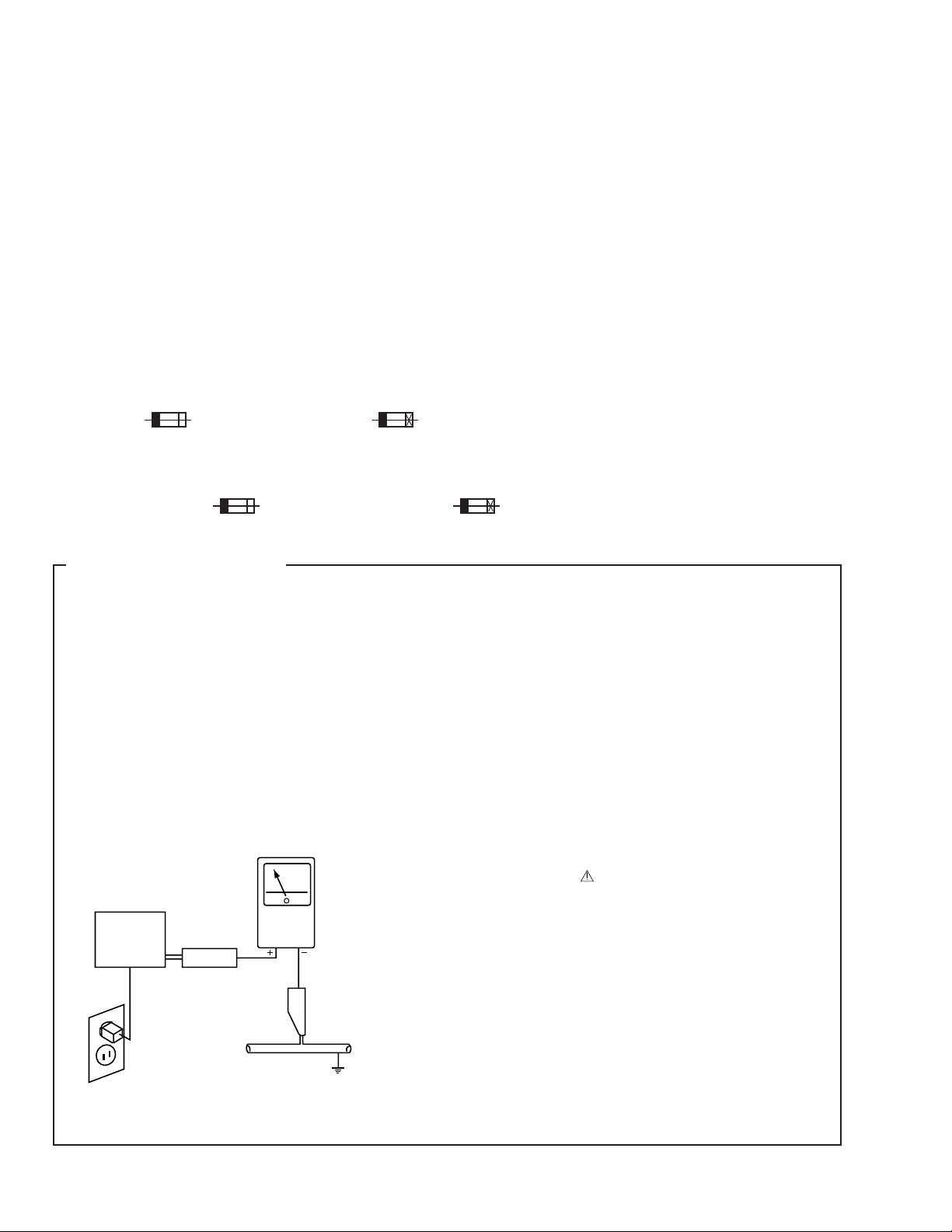
(FOR USA MODEL ONLY)
1. SAFETY PRECAUTIONS
The following check should be performed for the
continued protection of the customer and service
technician.
LEAKAGE CURRENT CHECK
Measure leakage current to a known earth ground (water
pipe, conduit, etc.) by connecting a leakage current tester
such as Simpson Model 229-2 or equivalent between the
earth ground and all exposed metal parts of the appliance
(input/output terminals, screwheads, metal overlays, control
shaft, etc.). Plug the AC line cord of the appliance directly
into a 120V AC 60Hz outlet and turn the AC power switch
on. Any current measured must not exceed 0.5mA.
Reading should
not be above
0.5mA
Earth
ground
Device
under
test
Also test with
plug reversed
(Using AC adapter
plug as required)
Leakage
current
tester
Test all
exposed metal
surfaces
ANY MEASUREMENTS NOT WITHIN THE LIMITS
OUTLINED ABOVE ARE INDICATIVE OF A POTENTIAL
SHOCK HAZARD AND MUST BE CORRECTED BEFORE
RETURNING THE APPLIANCE TO THE CUSTOMER.
2. PRODUCT SAFETY NOTICE
Many electrical and mechanical parts in the appliance
have special safety related characteristics. These are
often not evident from visual inspection nor the protection
afforded by them necessarily can be obtained by using
replacement components rated for voltage, wattage, etc.
Replacement parts which have these special safety
characteristics are identified in this Service Manual.
Electrical components having such features are identified
by marking with a
in this Service Manual.
The use of a substitute replacement component which does
not have the same safety characteristics as the PIONEER
recommended replacement one, shown in the parts list in
this Service Manual, may create shock, fire, or other hazards.
Product Safety is continuously under review and new
instructions are issued from time to time. For the latest
information, always consult the current PIONEER Service
Manual. A subscription to, or additional copies of, PIONEER
Service Manual may be obtained at a nominal charge from
PIONEER.
on the schematics and on the parts list
AC Leakage Test
2
Page 7
2. EXPLODED VIEWS AND PARTS LIST
NOTES:• Parts marked by "NSP" are generally unavailable because they are not in our Master Spare Parts List.
The mark found on some component parts indicates the importance of the safety factor of the part.
•
Therefore, when replacing, be sure to use parts of identical designation.
Screws adjacent to mark on the product are used for disassembly.
•
VSX-D307
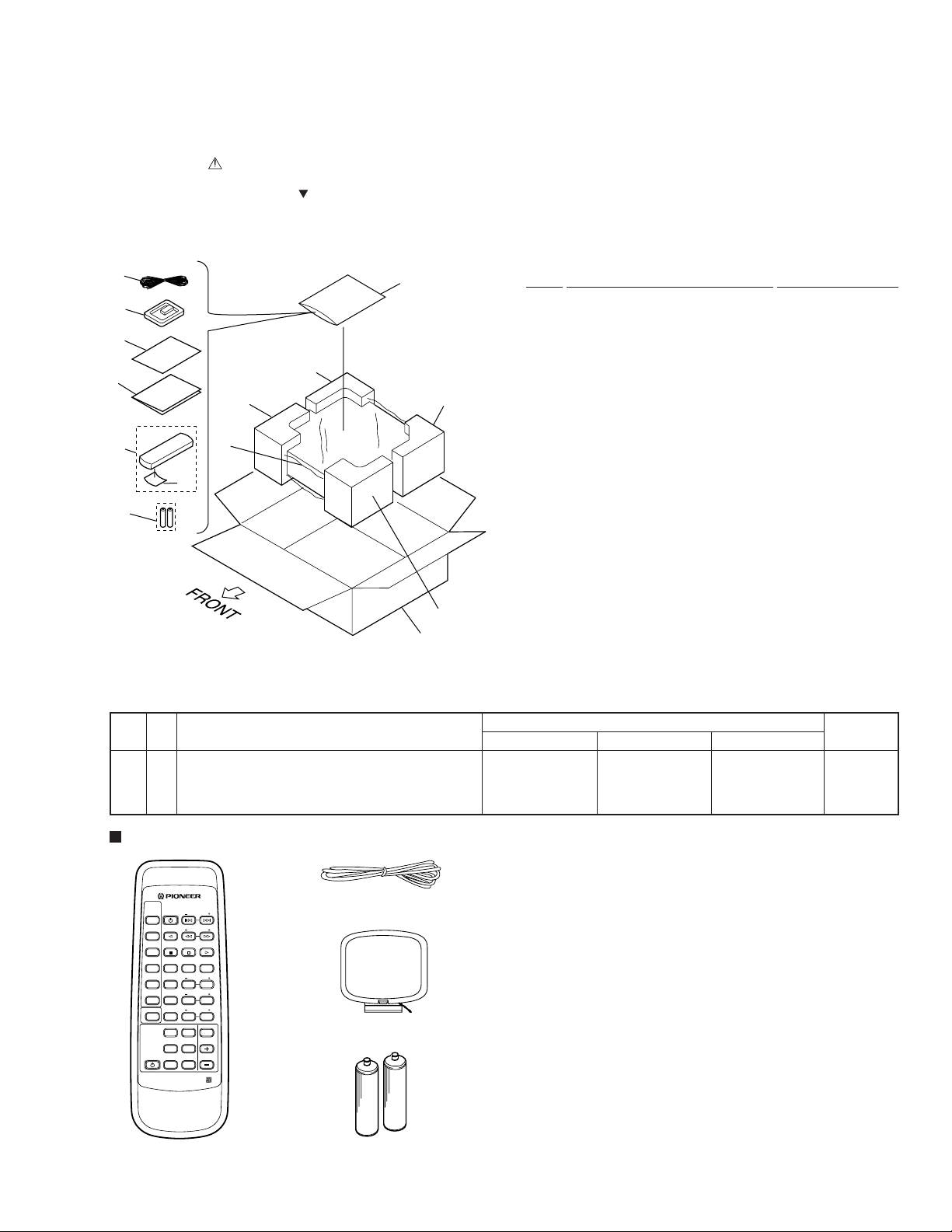
2.1 PACKING
(1) PACKING PARTS LIST
1
12
2
4
3
8 (1/2)
5
10
8 (2/2)
9 (2/2)
6
7
9 (1/2)
11
(2) CONTRAST TABLE
VSX-D307/KUXJ, KUXJI and KCXJI are constructed the same except for the following :
Mark No. Symbol and Description
3 Operating Instructions (English) ARB7136 ARB7136 Not used
3 Operating Instructions (English/French) Not used Not used ARE7159
NSP 4 Warranty Card ARY1051 ARY1051 ARY1075
11 Packing Case AHD7595 AHD7557 AHD7582
Mark No. Description Part No.
1 FM Antenna ADH7004
2 AM Loop Antenna ATB7009
3 Operating Instructions See Contrast table (2)
NSP 4 Warranty Card See Contrast table (2)
5 Remote Control Unit AXD7161
(CU-VSX124)
6 Battery Cover RZN1156
NSP 7 Dry Cell Battery (R6P, AA) VEM-013
8 Left Pad AHA7203
9 Right Pad AHA7204
10 Packing Sheet AHG1218
11 Packing Case See Contrast table (2)
12 Polyethylene Bag Z21-038
(0.03×230×340)
Part No.
VSX-D307/KUXJ VSX-D307/KUXJI VSX-D307/KCXJI
Remarks
Accessories
SOURCE
SELECT
CHANNEL
STATION
STANDBY/ON
CD
TV FUNC.
TV VOL.
TAPE
BAND
FREQ.
TUNER MPX
CLASS
D.ACCESS
DVD
123
TEST
REAR
TONE
LD
LEVEL
456
CENTER
CENTER
TV
LEVEL
MODE
CONTROL
789
CD DISC
DELAY
RECEIVER
STANDBY/ON
VIRTUAL
PRO LOGIC
EFFECT
TIME
0
DSP MODE
MUTING
LOUD.
MASTER
VOLUME
DIRECTFUNC.
SURROUND
AV MULTI-CHANNEL RECEIVER
REMOTE CONTROL UNIT
Remote Control Unit
(CU-VSX124 : AXD7161)
FM Antenna : ADH7004
AM Loop Antenna : ATB7009
Dry Cell Battery : VEM-013
(size “AA” IEC R6P) × 2
3
Page 8
VSX-D307
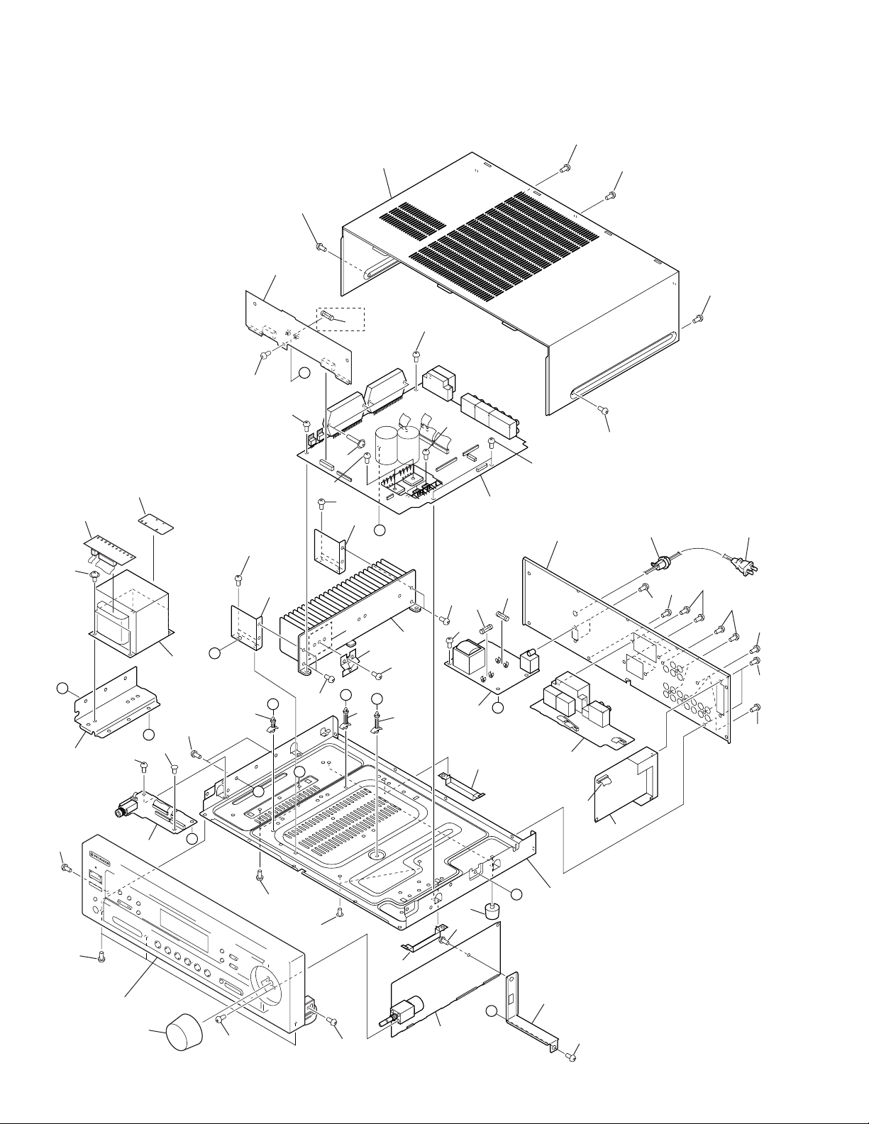
2.2 EXTERIOR SECTION
34
18
34
34
3
34
KCXJI Type
32
Only
34
34
D
34
34
34
36
5
6
34
34
20
1
E
34
17
14 13
34
35
34
20
28
D
10
A
C
26
34
B
19
34
27
B
A
34
F
24
22
E
23
34
24
34
34
11
12
F
7
Accessory of
Front Panel
8
34
34
34
34
34
34
15
34
4
C
34
Refer to
"2.3 FRONT PANEL SECTION".
33
4
34
34
27
34
29
9
G
16
30
25
21
G
2
34
Page 9
(1) EXTERIOR SECTION PARTS LIST
VSX-D307
Mark No. Description Part No.
1 MOTHER Assy See Contrast table (2)
2 VOLUME DSP Assy AWX7064
NSP 3 CONNECTION Assy See Contrast table (2)
4 HEADPHONE Assy AWX7066
NSP 5 TRANS 1 Assy AWX7070
NSP 6 TRANS 2 Assy AWX7071
7 PRIMARY Assy AWX7067
8 FRONT SPEAKER Assy AWX7068
9 FM/AM TUNER Unit AXX7046
10 Power Transformer ATS7205
(T1 : AC120V)
11 Fuse (FU2 : 8A) REK1086
12 Fuse (FU1 : 10A) REK1087
13 AC Power Cord PDG1057
14 Cord Stopper CM-22C
15 Flexible Cable 13P (J32) ADD7081
(MOTHER CN110-FM/AM TUNER Unit)
NSP 16 Under Base ANA7067
17 Rear Panel See Contrast table (2)
18 Bonnet Case AZN7710
19 T Angle ANG7178
20 H Angle ANG7179
Mark No. Description Part No.
21 PCB Angle ANG7180
22 FET Angle ANG7186
NSP 23 Heat Sink ANH7075
24 PCB Support AEC7006
25 Push Rivet AEC7025
26 PCB Support AEC7132
27 Card Spacer AEC7133
28 Mica Sheet AEE7026
29 Screw Cover AMR7199
30 Foot Assy REC1263
31 • • • • •
32 Fuse (FU91 : 10A) See Contrast table (2)
33 Round Knob AAB7082
34 Screw BBZ30P080FZK
35 Screw ABA7044
36 Screw ABA7043
(2) CONTRAST TABLE
VSX-D307/KUXJ, KUXJI and KCXJI are constructed the same except for the following :
Mark No. Symbol and Description
1 MOTHER Assy AWX7058 AWX7058 AWX7177
NSP 3 CONNECTION Assy AWX7060 AWX7060 AWX7176
17 Rear Panel ANC7663 ANC7627 ANC7691
32 Fuse (FU91 : 10A) Not used Not used REK1087
VSX-D307/KUXJ VSX-D307/KUXJI VSX-D307/KCXJI
Part No.
Remarks
5
Page 10

VSX-D307
2.3 FRONT PANEL SECTION
12
5
11
8
6 (2/2)
7
10
9
6 (1/2)
12
12
3
2
12
1
4
(1) FRONT PANEL SECTION PARTS LIST
Mark No. Description Part No.
1 FRONT Assy AWX7062
2 Flexible Cable 20P (J31) ADD7083
(MOTHER CN109-FRONT CN501)
3 Flexible Cable 20P (J35) ADD7083
(MOTHER CN111-FRONT CN502)
NSP 4 Getter AAX7631
5 Power Button AAD7440
6 Function Button AAD7441
7 PIONNER Badge PAM1755
8 LED Lens PNW2019
9 Sheet AAK7539
10 Sub Panel AAP7040
11 Front Panel AMB7494
12 Screw BPZ30P080FMC
6
Page 11

VSX-D307
7
Page 12
1
23
4
VSX-D307
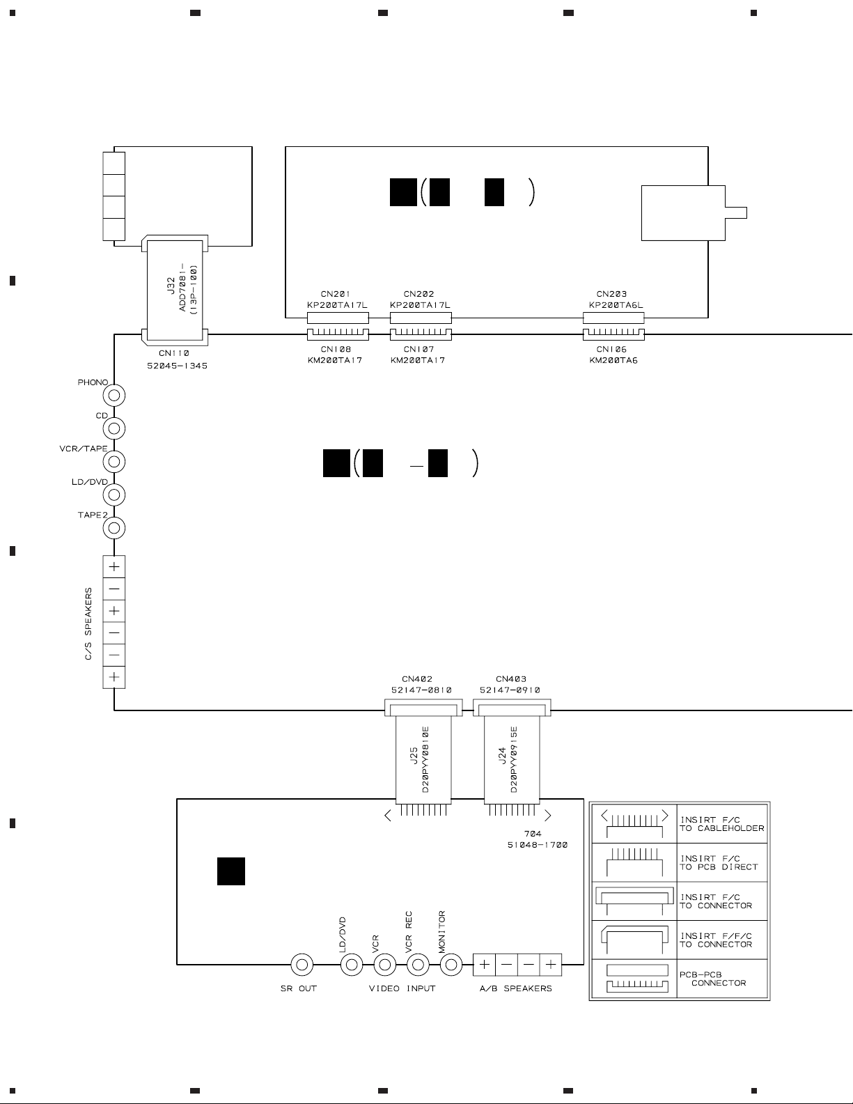
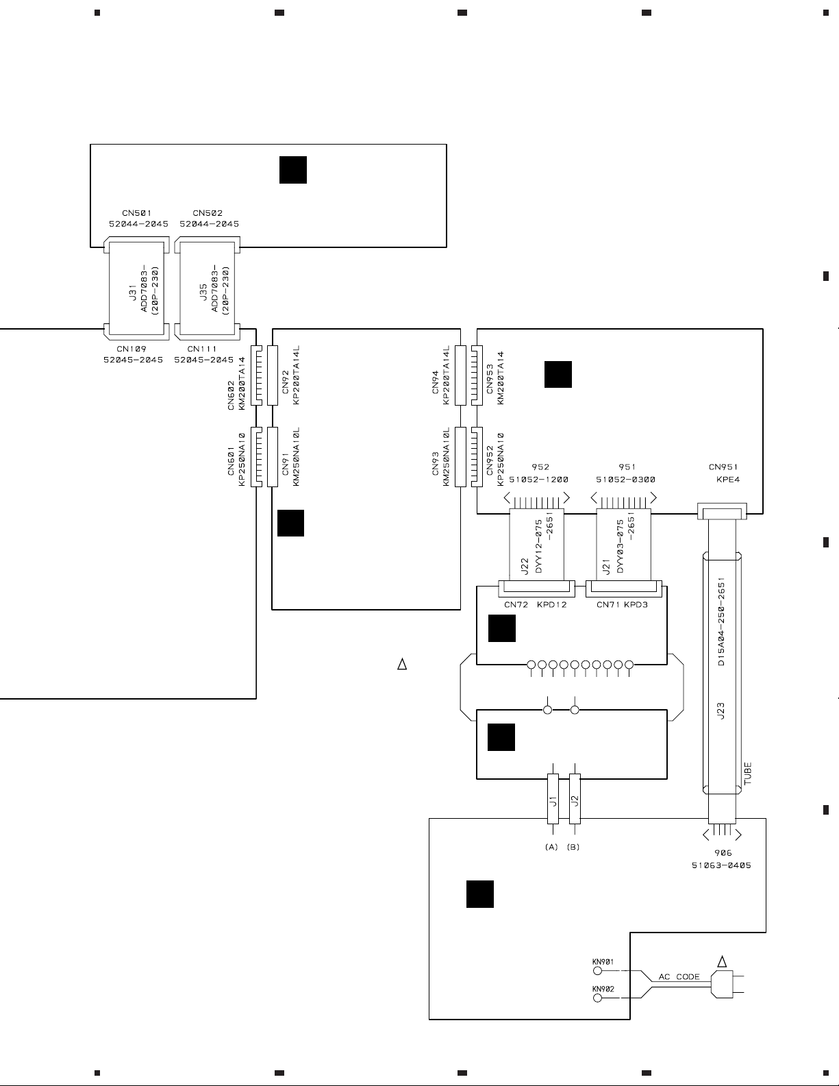
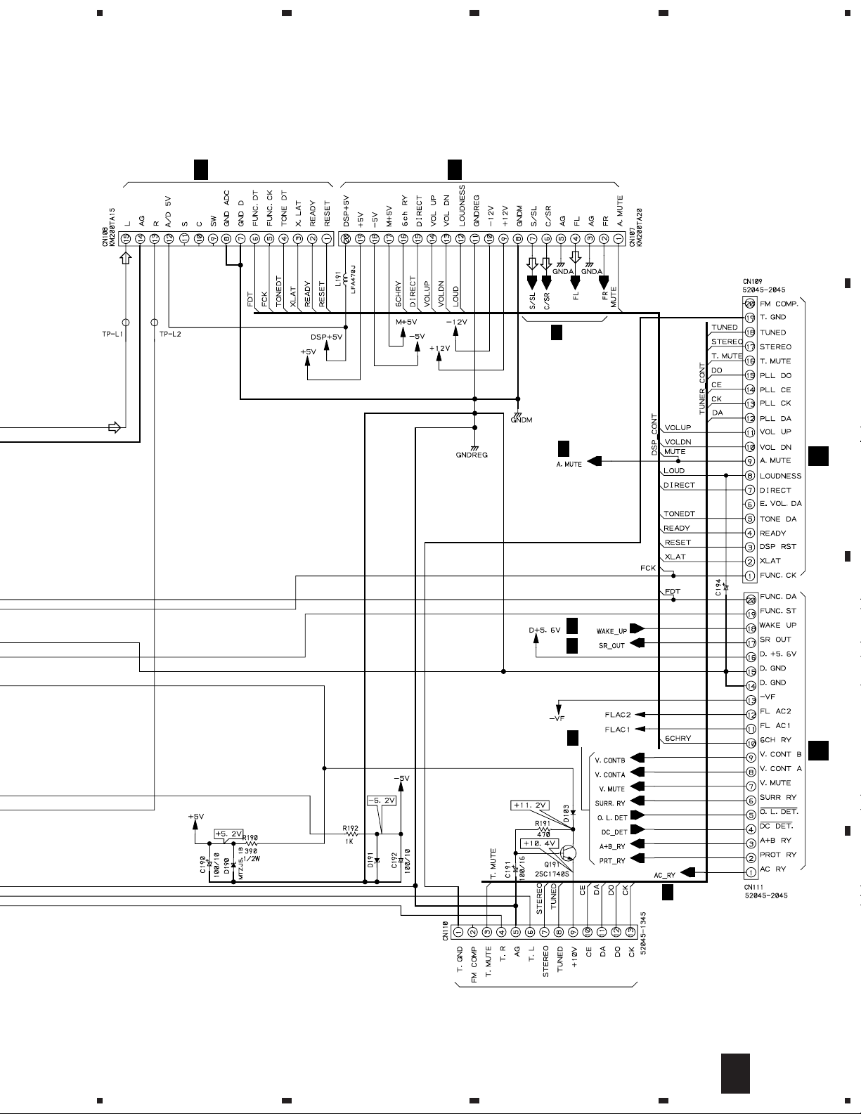
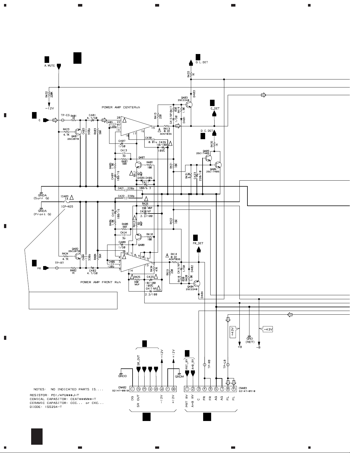
3. SCHEMATIC DIAGRAM
3.1 OVERALL CONNECTION DIAGRAM
Note : When ordering service parts, be sure to refer to "EXPLODED VIEWS and P AR TS LIST" or "PCB PARTS LIST".
A
FM/AM
TUNER UNIT
(AXX7046)
B
E
E
1/2E2/2
,
VOLUME DSP ASSY
(AWX7064)
A
A
1/3
A
3/3
MOTHER ASSY
(AWX7058 : KUXJ,KUXJI)
(AWX7177 : KCXJI)
C
FRONT SPEAKER ASSY
F
(AWX7068)
D
8
1234
Page 13
5
678
VSX-D307
A
D
FRONT ASSY
(AWX7062)
G
B
CONNECTION ASSY
(AWX7060:KUXJ,KUXJI)
(AWX7176:KCXJI)
!
T1
POWER
TRANSFORMER
ATS7205
HEADPHONE ASSY
(AWX7066)
TRANS 2 ASSY
C
(AWX7071)
TRANS 1 ASSY
I
(AWX7070)
B
C
PRIMARY ASSY
H
(AWX7067)
D
!
AC120V
60Hz
AC POWER CORD
PDG1057
9
5
6
7
8
Page 14
1
VSX-D307
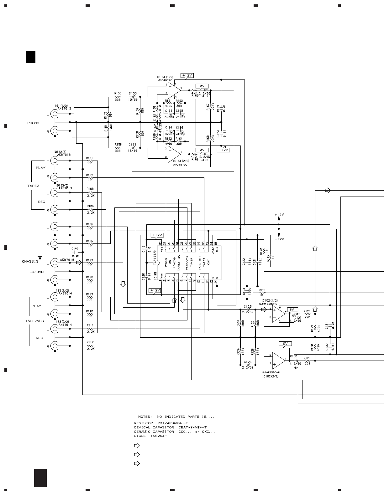
3.2 MOTHER ASSY (1/3)
23
4
A
A
MOTHER ASSY
1/3
(AWX7058:KUXJ,KUXJI)
IC151:
PHONO RIAA AMP
(AWX7177:KCXJI)
B
IC101:
CN102(1/2)
AKB7015
FUNCTION
SW
CN102(2/2)
IC102:
BUFFER AMP
C
D
10
: AUDIO SIGNAL ROUTE
(C)
: AUDIO SIGNAL ROUTE (CENTER)
(S)
: AUDIO SIGNAL ROUTE (SURROUND)
1/3
A
1234
Page 15
5
678
VSX-D307
A
CN201
E
1/2
E
1/2
CN202
(C)
(S)
A
2/3
B
A
2/3
CN501
D
MTZJ5.1B
Q191:
RIPPLE
FILTER
FOR TUNER
TO FM/AM TUNER UNIT
1/50
A
3/3
A
2/3
C
A
2/3
CN502
D
A
3/3
D
1/3
A
5
6
7
8
11
Page 16
1
VSX-D307
3.3 MOTHER ASSY (2/3)
A
A
1/3
A
1/3
(C)
A
23
MOTHER ASSY
2/3
(AWX7058:KUXJ,KUXJI)
(AWX7177:KCXJI)
(C)
!
IC401(2/2)
PAC007A
2SC2705
4
A
1/3
(C)
A
3/3
(C)
A
1/3
!
B
!
A
1/3
C
CAUTION : FOR CONTINUED PROTECTION AGAINST
RISK OF FIRE. REPLACE ONLY WITH
SAME TYPE NO. ICP-N25, MFD BY ROHM
CO., LTD. FOR IC403.
!
!
!
IC401(1/2)
PAC007A
!
2SC2705
!
A
3/3
!
!
A
1/3
A
1/3
V CONT B
V MUTE
V CONT A
D
12
V MUTE
V CONT B
F
2/3
A
1234
V CONT A
J25
VIDEO G
F
J24
Page 17

5
678
VSX-D307
A
(C) (C)
!
A
1/3
!
IC402(1/2)
PAC007A
!
!
2SC2705
!
2SC2705
!
!
(C)
A
3/3
B
(C)
!
A
3/3
!
A
1/3
(S)
(S)
IC402(2/2)
PAC007A
(S)
!
(S)
C
(C)
(C)
A
1/3
: AUDIO SIGNAL ROUTE
(C)
: AUDIO SIGNAL ROUTE (CENTER)
(S)
: AUDIO SIGNAL ROUTE (SURROUND)
(S)
(C)
(S)
(S)
(S)
D
2/3
A
5
6
7
8
13
Page 18

1
23
VSX-D307
3.4 MOTHER (3/3), CONNECTION AND TRANS 2 ASSEMBLIES
CAUTION : FOR CONTINUED PROTECTION AGAINST
RISK OF FIRE. REPLACE ONLY WITH
SAME TYPE NO. ICP-N25, MFD BY ROHM
A
A
2/3
!
B
!
!
CO., LTD. FOR IC607.
D625
MTZJ16B
4
MTZJ18B MTZJ18B
!
!
KUXJ,
A
1/3
C
(HP)
(HP)(HP)(HP)
KUXJI
ONLY
!
KCXJI
ONLY
0.01/250
0.01/250
KCXJI ONLY
B
FU91
!
CONNECTION ASSY
(AWX7060:KUXJ,KUXJI)
(AWX7176:KCXJI)
KUXJ,KUXJI
ONLY
10A
REK1087
(HP)
D
• NOTE FOR FUSE REPLACEMENT
CAUTION -
FOR CONTINUED PROTECTION AGAINST RISK OF FIRE.
REPLACE ONLY WITH SAME TYPE AND RATINGS ONLY.
14
3/3
A
1234
B
Page 19

5
678
VSX-D307
CN203
1/2
E
A
(HP)
HP G
(HP)
: AUDIO SIGNAL ROUTE (HEADPHONE)
A
(HP)
MOTHER ASSY
3/3
(AWX7058:KUXJ,KUXJI)
(AWX7177:KCXJI)
(HP)
!
!
(HP)
B
G
5
CN952
(HP)
CN953
G
(HP)(HP)
CAUTION : FOR CONTINUED PROTECTION AGAINST
RISK OF FIRE. REPLACE ONLY WITH
SAME TYPE NO. 491003 MFD, BY
LITTELFUSE INK. FOR IC71,IC72.
6
TRANS 2 ASSY
C
(AWX7071)
!
!
T1 POWER TRANSFORMER
3/3
A
7
B
C
8
C
J21
G
J22
G
D
15
Page 20

1
VSX-D307
3.5 FRONT ASSY
23
4
A
5
3
1
6
4
2
CN109
1/3
A
5
3
9
7
11
8
12
10
171915
13
16
14
1
20
18
6
4
2
CN111
1/3
A
9
7
11
8
12
10
171915
13
14
20
18
16
FRONT ASSY
D
(AWX7062)
B
REMOTE
RECEIVER
UNIT
C
STANDBY
IND.
D
16
D
1234
Page 21

5
678
VSX-D307
A
S501 : SPEAKER
S502 : SELECT
S503 : TAPE 2 MONITOR
S505 : TONE(–) / BALANCE(L)
S506 : PHONO
S507 : STANDBY / ON
S508 : TONE(+) / BALANCE(R)
S509 : FM / AM
S510 : STATION / FREQUENCY(–)
S511 : DOLBY PRO LOGIC
S512 : CD
S513 : MEMORY
S514 : DOLBY VIRTUAL
S515 : DVD / LD
S516 : STATION / FREQUENCY(+)
S517 : LOUDNESS
S518 : VCR / TAPE 1
S520 : DSP MODE
S522 : CLASS
S523 : TUNING SELECT
S524 : MPX MODE
VNF1096
FL HOLDER
FL TUBE
B
C
D
D
5
6
7
8
17
Page 22

1
VSX-D307
3.6 VOLUME DSP ASSY (1/2)
A
23
E
1/2
VOLUME DSP ASSY(AWX7064)
IC206:
44kHz L.P.F.
(S)
(C)
4
B
C
100p
(S)
(C)
(S)
(C)
(S)
(C)
(C)
(S)
D
18
E
CN201
KP200TA15L
CN108
1/3
A
1/2
1234
Page 23

5
IC202:
TONE CONTROL
678
VSX-D307
A
MTZJ9.1B
IC207:
6dB AMP
E
2/2
E
2/2
B
E
2/2
: AUDIO SIGNAL ROUTE
(C)
(S)
+5V
(C)
(C) (C)
E
2/2
(S) (S)
(S)
E
2/2
IC211:
(C)
: AUDIO SIGNAL ROUTE (CENTER)
(S)
: AUDIO SIGNAL ROUTE (SURROUND)
(HP)
: AUDIO SIGNAL ROUTE (HEADPHONE)
C
44kHz L.P.F. & AMP
E
2/2
(S)
E
(C)
2/2
(HP)
–5V
E
2/2
CN202
KP200TA20L
(S)
(C)
CN106
3/3
A
CN107
1/3
A
1/2
E
5
6
7
8
19
D
Page 24

1
23
VSX-D307
3.7 VOLUME DSP ASSY (2/2)
4
A
B
E
VOLUME DSP ASSY(AWX7064)
2/2
1/2
E
1/2
E
1/2
E
1/2
E
IC204(BU4052BCF) CONTROL
C
D
20
2/2
E
1234
: AUDIO SIGNAL ROUTE
(C)
: AUDIO SIGNAL ROUTE (CENTER)
(S)
: AUDIO SIGNAL ROUTE (SURROUND)
Page 25

5
678
VSX-D307
A
IC301:
PRE-AMP
IC301(1/2)
UPC4570C
1/2
E
1SS254
1SS254
1/2
IC301(2/2)
UPC4570C
E
B
E
E
1/2
1/2
E
(C)
(S)
1/2
E
1/2
Q311
KRA101M
1SS254
IC302:
PRE-AMP
IC302(2/2)
UPC4570C
(C)
(C)
(S)
IC302(1/2)
UPC4570C
(C)
(S)
(S)
E
E
1/2
1/2
C
1/2
E
D
2/2
E
5
6
7
8
21
Page 26

1
23
4
VSX-D307
3.8 FRONT SPEAKER, HEADPHONE, PRIMARY AND TRANS 1 ASSEMBLIES
A
FRONT SPEAKER ASSY
F
(AWX7068)
CN403
2/3
CN701 AKE7030
A
CN402
B
2/3
A
IC801:
VIDEO SW
Q802
2SA933S
C
IC801(NJM2279D) LOGIC
: AUDIO SIGNAL ROUTE
D
1SS254
22
F
1234
Page 27

5
678
VSX-D307
• NOTE FOR FUSE REPLACEMENT
CAUTION -
FOR CONTINUED PROTECTION AGAINST RISK OF FIRE.
REPLACE ONLY WITH SAME TYPE AND RATINGS ONLY.
A
AC
POWER
CORD
LIVE
NEUTRAL
FU1:REK1087
FU1
10000p/250
10A
2.2M 1/2W
10000p/250
ASR7016
1SS254
FU2:REK1086
FU2
8A
RY901:
POWER RELAY
H
PRIMARY ASSY (AWX7067)
G
HEADPHONE ASSY
(AWX7066)
C
CN71
T1
POWER
TRANSFORMER
TRANS 1 ASSY
I
(AWX7070)
B
(HP)
: AUDIO SIGNAL ROUTE (HEADPHONE)
C
CN72
(HP)
B
CN93
C
B
CN94
(HP)
D
PHONES
H.P. JACK
23
HG
5
6
7
I
8
Page 28

1
C
23
VSX-D307
4. PCB CONNECTION DIAGRAM
4.1 MOTHER ASSY
NOTE FOR PCB DIAGRAMS :
1. Part numbers in PCB diagrams match those in the schematic
A
diagrams.
2. A comparison between the main parts of PCB and schematic
diagrams is shown below.
Symbol In PCB
Diagrams
BCE
D
3. The parts mounted on this PCB include all necessary parts for
several destinations.
B
For further information for respective destinations, be sure to
check with the schematic diagram.
4. View point of PCB diagrams.
Connector
BCE
Symbol In Schematic
Diagrams
BCEBCE
BCE
BCE
DGS
DGGSS
Capacitor
SIDE A
Part Name
Transistor
Transistor
with resistor
Field effect
transistor
Resistor array
3-terminal
regulator
D
CN501
MOTHER ASSY
A
4
FM/AM TUNER UNIT
E
C
P.C.Board
Chip Part
SIDE B
D
CN502
J25
F
J24
F
D
SIDE A
Q103 Q605Q191Q192IC102IC101IC151
Q453
IC402
Q457Q454Q406 Q405
24
A
1234
Q101
Q458Q456 Q455 Q452
Page 29

5
678
VSX-D307
UNIT
E
CN201
CN202
E
A
E
CN203
B
91
Q605
B
CN92
C
B
CN91
D
(ANP7242-A)
IC606
IC601-IC603
5
6
IC607
IC604
7
Q651-Q654
IC651Q604Q402-Q404Q407Q401Q451Q457
Q603Q601Q602Q408IC401
A
8
25
Page 30

1
23
VSX-D307
4.2 CONNECTION, TRANS 2 AND FRONT ASSEMBLIES
4
A
B
CONNECTION ASSY
B
CN602
A
A
CN601
FRONT ASSY
D
C
D
26
B D
Q583Q501IC581Q582Q581Q503
Q502
SIDE A
1234
Page 31

5
678
VSX-D307
TRANS 2 ASSY
C
T1 POWER TRANSFORMER
(ANP7242-A)
A
G
CN952
IC201
G
CN953
A
G
CN111
J21
G
CN109
A
J22
B
C
D
(ANP7243-B)
Q505Q504IC201
SIDE A
DCB
5
6
7
8
27
Page 32

1
VSX-D307
4.3 VOLUME DSP ASSY
23
4
A
VOLUME DSP ASSY
E
A
CN108
IC201
IC206
B
IC205
A
IC202
IC202
Q202
CN107
IC211
Q311
IC302
IC207
C
IC301
Q313-Q316
IC208
IC209
A
CN106
D
Q302
IC204
IC204
Q301
(ANP7243-B)
28
SIDE A
E
1234
Page 33

1
234
VSX-D307
4.4 FRONT SPEAKER, HEADPHONE, PRIMARY AND TRANS 1 ASSEMBLIES
Q702 Q701
Q704 Q801
Q703 Q802 IC801 IC751 IC752
FRONT
F
SPEAKER
A
CN403
A
CN402
ASSY
A
B
PRIMARY ASSY
H
CN93
B
B
CN94
TRANS 1
I
ASSY
AC POWER
CORD
T1
POWER TRANSFORMER
C
C
CN71
1
C
CN72
2
SIDE A
HEADPHONE
G
ASSY
(ANP7243-B)
3
D
29
IHGF
4
Page 34

VSX-D307
Mark No. Description Part No.Mark No. Description Part No.
5. PCB PARTS LIST
NOTES:•Parts marked by "NSP" are generally unavailable because they are not in our Master Spare Parts List.
The mark found on some component parts indicates the importance of the safety factor of the part.
•
Therefore, when replacing, be sure to use parts of identical designation.
When ordering resistors, first convert resistance values into code form as shown in the following examples.
•
Ex.1 When there are 2 effective digits (any digit apart from 0), such as 560 ohm and 47k ohm (tolerance is shown by J=5%,
and K=10%).
560 Ω→56 × 10
47k Ω→47 × 103→ 473 ........................................................ RD1/4PU 4 7 3 J
0.5 Ω→R50 .....................................................................................RN2H
1 Ω→1R0 .....................................................................................RS1P
Ex.2 When there are 3 effective digits (such as in high precision metal film resistors).
5.62k Ω→ 562 × 10
LIST OF WHOLE PCB ASSEMBLIES
Mark Symbol and Description
NSP MAIN ASSY AWK7423 AWX7423 AWK7462
MOTHER ASSY AWX7058 AWX7058 AWX7177
NSP CONNECTION ASSY AWX7060 AWX7060 AWX7176
NSP TRANS 2 ASSY AWX7071 AWX7071 AWX7071
1
→ 561 ........................................................ RD1/4PU 5 6 1 J
R 5 0
1 R 0
1
→ 5621 ...................................................... RN1/4PC 5 6 2 1 F
Part No.
VSX-D307/KUXJ VSX-D307/KUXJI VSX-D307/KCXJI
K
K
Remarks
NSP COMPLEX ASSY AWK7425 AWK7425 AWK7425
FRONT ASSY AWX7062 AWX7062 AWX7062
VOLUME DSP ASSY AWX7064 AWX7064 AWX7064
FRONT SPEAKER ASSY AWX7068 AWX7068 AWX7068
HEADPHONE ASSY AWX7066 AWX7066 AWX7066
PRIMARY ASSY AWX7067 AWX7067 AWX7067
NSP TRANS 1 ASSY AWX7070 AWX7070 AWX7070
Mark No. Description Part No.Mark No. Description Part No.
MOTHER ASSY
A
(1) CONTRAST TABLE
AWX7058 and AWX7177 are constructed the same except
for the following :
Mark Symbol and Description
IC607 Not used ICP-N25
Part No.
AWX7058 AWX7177
Remarks
(2) PARTS LIST FOR AWX7058
SEMICONDUCTORS
IC101 E-SW IC TC9163AN
IC102 OP-AMP IC NJM4558D-D
IC151 IC UPC4570C
IC401 AUDIO IC PAC007A
IC402 AUDIO IC PAC007A
IC403 IC PROTECTOR ICP-N25
IC601 REGULATOR IC NJM78M12FA
IC602 REGULATOR IC NJM79M12FA
IC603 REGULATOR IC NJM78M05FA
IC604 OP-AMP IC NJM4558D-D
IC605 OP-AMP IC NJM4558D-D
IC606 REGULATOR IC NJM78M05FA
IC651 OP-AMP IC NJM4558D-D
Q191 TRANSISTOR 2SC1740S
Q401 TRANSISTOR 2SC2878
Q402 TRANSISTOR 2SC2878
Q403 TRANSISTOR 2SC2240
Q404 TRANSISTOR 2SC2240
Q405 TRANSISTOR 2SC1740S
Q406 TRANSISTOR 2SC1740S
Q407 TRANSISTOR 2SC2705
Q408 TRANSISTOR 2SC2705
Q451 TRANSISTOR 2SC2878
Q452 TRANSISTOR 2SC2878
Q453 TRANSISTOR 2SC2240
Q454 TRANSISTOR 2SC2240
Q455 TRANSISTOR KRA103M
Q456 TRANSISTOR KRC101M
Q457 TRANSISTOR 2SC2705
Q458 TRANSISTOR 2SC2705
Q601 POWER MOS FET IRF9540A
Q602 POWER MOS FET IRF540A
Q603 TRANSISTOR 2SC1845
Q604 TRANSISTOR 2SA992
Q651 TRANSISTOR 2SC2878
Q652 TRANSISTOR 2SC2878
Q653 TRANSISTOR 2SC2878
Q654 TRANSISTOR 2SC2878
D103 DIODE 1SS254
D190 ZENER DIODE MTZJ5.1B
30
Page 35

D191 ZENER DIODE MTZJ5.1B
D401 DIODE 1SS254
D402 DIODE 1SS254
D403 DIODE 1SS254
D404 DIODE 1SS254
VSX-D307
Mark No. Description Part No.Mark No. Description Part No.
C163 FILM CAPACITOR CQMBA822J50
C164 FILM CAPACITOR CQMBA822J50
C165 MYLAR FILM CAPACITOR CQMA242J50
C166 MYLAR FILM CAPACITOR CQMA242J50
C167 ELECT. CAPACITOR CEAT2R2M50
D405 DIODE 1SS254
D406 DIODE 1SS254
D451 DIODE 1SS254
D452 DIODE 1SS254
D453 DIODE 1SS254
D454 DIODE 1SS254
D455 DIODE 1SS254
D457 DIODE 1SS254
D458 DIODE 1SS254
D601 DIODE GBU6D
D602 DIODE GBU6D
D603 DIODE S5688G
D604 DIODE S5688G
D605 DIODE S5688G
D606 DIODE S5688G
D607 ZENER DIODE MTZJ18B
D608 ZENER DIODE MTZJ18B
D609 DIODE 1SS254
D610 DIODE 1SS254
D611 DIODE 1SS254
D612 DIODE 1SS254
D613 DIODE 1SS254
D614 DIODE 1SS254
D615 DIODE 1SS254
D616 DIODE 1SS254
D617 DIODE 1SS254
D618 DIODE 1SS254
D619 DIODE S5688G
D620 DIODE S5688G
D623 ZENER DIODE MTZJ27B
C168 ELECT. CAPACITOR CEAT2R2M50
C169 CERAMIC CAPACITOR CKCYF103Z50
C170 CERAMIC CAPACITOR CKCYF103Z50
C190 ELECT. CAPACITOR CEAT101M10
C191 ELECT. CAPACITOR CEAT101M16
C192 ELECT. CAPACITOR CEAT101M10
C194 ELECT. CAPACITOR CEAT1R0M50
C199 CERAMIC CAPACITOR CGCYX103M16
C401 ELECT. CAPACITOR CEAT4R7M50
C402 ELECT. CAPACITOR CEAT4R7M50
C403 CERAMIC CAPACITOR CCCSL331J50
C404 CERAMIC CAPACITOR CCCSL331J50
C405 CERAMIC CAPACITOR CCCSL121J50
C406 CERAMIC CAPACITOR CCCSL121J50
C407 ELECT. CAPACITOR CEAT1R0M50
C408 ELECT. CAPACITOR CEAT1R0M50
C409 ELECT. CAPACITOR CEAT101M16
C410 ELECT. CAPACITOR CEAT101M16
C411 ELECT. CAPACITOR CEAT101M6R3
C413 CERAMIC CAPACITOR CCCSL3R0C50
C414 CERAMIC CAPACITOR CCCSL3R0C50
C415 ELECT. CAPACITOR CEANP1R0M50
C416 ELECT. CAPACITOR CEANP1R0M50
C417 ELECT. CAPACITOR CEANP2R2M2A
C420 ELECT. CAPACITOR CEANP2R2M2A
C421 CERAMIC CAPACITOR CCCSL221J50
C422 CERAMIC CAPACITOR CCCSL221J50
C423 ELECT. CAPACITOR CEAT221M10
C425 ELECT. CAPACITOR CEHAQ100M2A
C426 ELECT. CAPACITOR CEHAQ100M2A
D624 ZENER DIODE MTZJ6.8A
D625 ZENER DIODE MTZJ16B
RELAY
RY401 RELAY ASR7014
COILS
L191 RADIAL INDUCTOR LFA470J
L451 COIL (0.7mH) ATH1004
L452 COIL (0.7mH) ATH1004
CAPACITORS
C119 CERAMIC CAPACITOR CKCYF103Z50
C120 CERAMIC CAPACITOR CKCYF103Z50
C121 CERAMIC CAPACITOR CCCSL101J50
C122 CERAMIC CAPACITOR CCCSL101J50
C123 CERAMIC CAPACITOR CCCSL101J50
C125 ELECT. CAPACITOR CEAT2R2M50
C126 ELECT. CAPACITOR CEAT2R2M50
C129 ELECT. CAPACITOR CEANP4R7M50
C130 ELECT. CAPACITOR CEANP4R7M50
C131 CERAMIC CAPACITOR CKCYF103Z50
C132 CERAMIC CAPACITOR CKCYF103Z50
C155 ELECT. CAPACITOR CEAT100M50
C156 ELECT. CAPACITOR CEAT100M50
C161 ELECT. CAPACITOR CEAT470M25
C162 ELECT. CAPACITOR CEAT470M25
C430 CERAMIC CAPACITOR CKCYF103Z50
C451 ELECT. CAPACITOR CEAT4R7M50
C452 ELECT. CAPACITOR CEAT4R7M50
C453 CERAMIC CAPACITOR CCCSL331J50
C454 CERAMIC CAPACITOR CCCSL331J50
C455 CERAMIC CAPACITOR CCCSL121J50
C456 CERAMIC CAPACITOR CCCSL121J50
C457 ELECT. CAPACITOR CEAT1R0M50
C458 ELECT. CAPACITOR CEAT1R0M50
C459 ELECT. CAPACITOR CEAT101M16
C460 ELECT. CAPACITOR CEAT101M16
C461 ELECT. CAPACITOR CEAT101M6R3
C463 CERAMIC CAPACITOR CCCSL3R0C50
C464 CERAMIC CAPACITOR CCCSL3R0C50
C465 ELECT. CAPACITOR CEANP1R0M50
C466 ELECT. CAPACITOR CEANP1R0M50
C467 ELECT. CAPACITOR CEANP2R2M2A
C469 ELECT. CAPACITOR CEANP2R2M2A
C471 CERAMIC CAPACITOR CCCSL221J50
C472 CERAMIC CAPACITOR CCCSL221J50
C473 AUDIO FILM CAPACITOR CFTYA104J50
C474 AUDIO FILM CAPACITOR CFTYA104J50
C477 ELECT. CAPACITOR CEHAQ100M2A
C478 ELECT. CAPACITOR CEHAQ100M2A
C490 CERAMIC CAPACITOR CKCYF103Z50
31
Page 36

VSX-D307
C601 ELECTROLYTIC CAPACITOR ACH7018
(8200µF/71V)
C602 ELECTROLYTIC CAPACITOR ACH7018
(8200µF/71V)
C603 ELECT. CAPACITOR CEAT101M2A
C604 ELECT. CAPACITOR CEAT101M2A
C605 ELECT. CAPACITOR CEAT222M25
C606 ELECT. CAPACITOR CEAT102M25
C607 CERAMIC CAPACITOR CKCYF103Z50
C608 CERAMIC CAPACITOR CKCYF103Z50
C609 ELECT. CAPACITOR CEAT101M25
C610 ELECT. CAPACITOR CEAT101M25
C611 CERAMIC CAPACITOR CKCYF103Z50
C612 ELECT. CAPACITOR CEAT470M10
C613 ELECT. CAPACITOR CEAT1R0M50
C614 ELECT. CAPACITOR CEAT1R0M50
C615 CERAMIC CAPACITOR CKCYF103Z50
C616 CERAMIC CAPACITOR CKCYF103Z50
C617 CERAMIC CAPACITOR CKCYF103Z50
C618 CERAMIC CAPACITOR CKCYF103Z50
C619 ELECT. CAPACITOR CEAT4R7M50
C620 ELECT. CAPACITOR CEAT470M50
C621 CKA (0.01µF/AC250V) ACG1005
C622 CKA (0.01µF/AC250V) ACG1005
C624 ELECT. CAPACITOR CEAT101M35
C625 ELECT. CAPACITOR CEAT101M10
C626 ELECT. CAPACITOR CEAT221M25
C627 CERAMIC CAPACITOR CKCYF103Z50
C628 ELECT. CAPACITOR CEAT470M10
C631 FILM CAPACITOR CFTLA334J50
C632 FILM CAPACITOR CFTLA334J50
C633 FILM CAPACITOR CFTLA334J50
C634 FILM CAPACITOR CFTLA334J50
C651 CERAMIC CAPACITOR CKCYF103Z50
C652 CERAMIC CAPACITOR CKCYF103Z50
C653 ELECT. CAPACITOR CEAT100M50
C654 ELECT. CAPACITOR CEAT100M50
C657 ELECT. CAPACITOR CEAT101M16
C658 ELECT. CAPACITOR CEAT101M16
Mark No. Description Part No.Mark No. Description Part No.
R629 METAL OXIDE RESISTOR RS1LMF561J
R663 CARBON FILM RESISTOR RD1/4MUF330J
R664 CARBON FILM RESISTOR RD1/4MUF330J
Other Resistors RD1/4PU J
OTHERS
101 PIN JACK(6P) AKB7013
103 PIN JACK(4P) AKB7014
CN102 PIN JACK(4P) AKB7015
CN106 6P PLUG KM200TA6
CN107 20P PLUG KM200TA20
CN108 15P PLUG KM200TA15
CN109 20P CONNECTOR 52045-2045
CN110 CONNECTOR 52045-1345
CN111 20P CONNECTOR 52045-2045
CN401 SPEAKER TERMINAL 6-P AKE1053
CN402 8P JUMPER CONNECTOR 52147-0810
CN403 9P JUMPER CONNECTOR 52147-0910
CN601 10P SOCKET KP250NA10
CN602 14P PLUG KM200TA14
CONNECTION ASSY
B
(1) CONTRAST TABLE
AWX7060 and AWX7176 are constructed the same except
for the following :
Mark Symbol and Description
H91,H92 Fuse Clip Not used AKR1004
Part No.
AWX7060 AWX7176
Remarks
(2) PARTS LIST FOR AWX7060
OTHERS
CN91 10P PLUG KM250NA10L
CN92 14P SOCKET KP200TA14L
CN93 10P PLUG KM250NA10L
CN94 14P SOCKET KP200TA14L
RESISTORS
R190 CARBON FILM RESISTOR RD1/2PM391J
R411 CARBON FILM RESISTOR RD1/4MUF820J
R412 CARBON FILM RESISTOR RD1/4MUF820J
R413 RESISTOR (0.22Ω, 5W) ACN7035
R414 RESISTOR (0.22Ω, 5W) ACN7035
R425 CARBON FILM RESISTOR RD1/4MUF331J
R426 CARBON FILM RESISTOR RD1/4MUF331J
R461 CARBON FILM RESISTOR RD1/4MUF820J
R462 CARBON FILM RESISTOR RD1/4MUF820J
R463 RESISTOR (0.22Ω, 5W) ACN7035
R464 RESISTOR (0.22Ω, 5W) ACN7035
R475 CARBON FILM RESISTOR RD1/4MUF331J
R476 CARBON FILM RESISTOR RD1/4MUF331J
R477 CARBON FILM RESISTOR RD1/4PMF4R7J
R478 CARBON FILM RESISTOR RD1/4PMF4R7J
R479 METAL OXIDE RESISTOR RS1LMF4R7J
R480 METAL OXIDE RESISTOR RS1LMF4R7J
R601 METAL OXIDE RESISTOR RS2LMF330J
R603 CARBON FILM RESISTOR RD1/4PMF101J
R604 CARBON FILM RESISTOR RD1/4PMF101J
32
TRANS 2 ASSY
C
SEMICONDUCTORS
IC71 PROTECTOR(3A) AEK7015
IC72 PROTECTOR(3A) AEK7015
OTHERS
CN71 3P JUMPER CONNECTOR KPD3
CN72 12P JUMPER CONNECTOR KPD12
COMPLEX ASSY
OTHERS
J1 LEAD WIRE UNIT DB115NB0
Page 37

FRONT ASSY
D
SEMICONDUCTORS
IC501 CONTROL MCU PDG211A
Q501 TRANSISTOR KRA101M
Q502 TRANSISTOR KRC101M
Q503 TRANSISTOR KRA103M
Q504 TRANSISTOR KRC101M
Q505 TRANSISTOR 2SA933S
D501 DIODE 1SS254
D502 LED BR3371XJ30A
D503 DIODE 1SS254
D504 DIODE 1SS254
VSX-D307
Mark No. Description Part No.Mark No. Description Part No.
C507 AXIAL CAPACITOR CKPUYB101K50
C508 AXIAL CAPACITOR CKPUYB101K50
C509 AXIAL CAPACITOR CKPUYB101K50
C510 CERAMIC CAPACITOR CKCYF103Z50
C511 ELECT. CAPACITOR CEAT470M50
C512 ELECT. CAPACITOR CEAT221M10
C513 CERAMIC CAPACITOR CGCYX103M16
C514 CAPACITOR ACH7013
C516 CERAMIC CAPACITOR CKPUYF473Z16
C517 ELECT. CAPACITOR CEAT221M35
C518 AUDIO FILM CAPACITOR CFTYA104J50
C522 CERAMIC CAPACITOR CKPUYF473Z16
C523 CERAMIC CAPACITOR CKPUYB102K50
D505 DIODE 1SS254
D506 DIODE 1SS254
D507 DIODE 1SS254
D508 DIODE 1SS254
D509 DIODE 1SS254
D510 DIODE 1SS254
D511 DIODE 1SS254
D512 DIODE 1SS254
D513 DIODE 1SS254
D514 DIODE 1SS254
D518 DIODE 1SS254
D519 DIODE 1SS254
D520 DIODE 1SS254
D521 DIODE 1SS254
SWITCHES
S501 SWITCH ASG1034
S502 SWITCH ASG1034
S503 SWITCH ASG1034
S505 SWITCH ASG1034
S506 SWITCH ASG1034
S507 SWITCH ASG1034
S508 SWITCH ASG1034
S509 SWITCH ASG1034
S510 SWITCH ASG1034
S511 SWITCH ASG1034
S512 SWITCH ASG1034
S513 SWITCH ASG1034
S514 SWITCH ASG1034
S515 SWITCH ASG1034
S516 SWITCH ASG1034
S517 SWITCH ASG1034
S518 SWITCH ASG1034
S520 SWITCH ASG1034
S522 SWITCH ASG1034
S523 SWITCH ASG1034
S524 SWITCH ASG1034
COILS
L501 AXIAL INDUCTOR LAU2R2J
L502 AXIAL INDUCTOR LAUR22J
CAPACITORS
C501 CERAMIC CAPACITOR CKPUYF103Z25
C502 CERAMIC CAPACITOR CKPUYF103Z25
C503 CERAMIC CAPACITOR CKPUYF473Z16
C504 ELECT. CAPACITOR CEAT2R2M50
C505 CERAMIC CAPACITOR CGCYX104M16
RESISTORS
All Resistors RD1/4PU J
OTHERS
501 REMOTE RECEIVER UNIT GP1U27X
CN501 20P CONNECTOR 52044-2045
CN502 20P CONNECTOR 52044-2045
V501 FL TUBE AAV7053
X501 CERAMIC RESONATOR ASS7018
VOLUME DSP ASSY
E
(7.2MHz)
SEMICONDUCTORS
IC201 DSP IC CXD2724Q
IC202 E-VR IC M62420FP
IC204 LOGIC IC BU4052BCF
IC206 OP-AMP IC NJM4558LD
IC207 OP-AMP IC NJM4558LD
IC211 OP-AMP IC NJM4558D-D
IC301 IC UPC4570C
IC302 IC UPC4570C
Q202 TRANSISTOR 2SC1740S
Q301 N-FET 2SK246
Q302 N-FET 2SK246
Q311 TRANSISTOR KRA101M
Q313 TRANSISTOR 2SA1115
Q314 TRANSISTOR 2SC2603
Q315 TRANSISTOR 2SA1115
Q316 TRANSISTOR 2SC2603
D201 ZENER DIODE MTZJ5.6B
D203 ZENER DIODE MTZJ5.6B
D204 ZENER DIODE MTZJ9.1B
D301 DIODE 1SS254
D302 DIODE 1SS254
D303 DIODE 1SS254
COILS
L202 AXIAL INDUCTOR LAU1R0J
L207 AXIAL INDUCTOR LAU220J
L208 AXIAL INDUCTOR LAU1R0J
CAPACITORS
C201 ELECT. CAPACITOR CEAT470M16
C202 ELECT. CAPACITOR CEAT470M16
C203 ELECT. CAPACITOR CEAT471M6R3
C204 CERAMIC CAPACITOR CCCSL101J50
C205 CERAMIC CAPACITOR CKPUYB331K50
33
Page 38

VSX-D307
C206 AXIAL CERAMIC C. CCPUCH120J50
C207 AXIAL CERAMIC C. CCPUCH120J50
C208 CERAMIC CAPACITOR CKPUYB331K50
C209 CERAMIC CAPACITOR CCCSL101J50
C211 ELECT. CAPACITOR CEATR22M50
Mark No. Description Part No.Mark No. Description Part No.
C306 ELECT. CAPACITOR CEAT4R7M50
C307 ELECT. CAPACITOR CEAT4R7M50
C308 ELECT. CAPACITOR CEAT4R7M50
C309 CERAMIC CAPACITOR CKCYF103Z50
C310 CERAMIC CAPACITOR CKCYF103Z50
C212 ELECT. CAPACITOR CEATR22M50
C213 CERAMIC CAPACITOR CKCYF103Z50
C214 CERAMIC CAPACITOR CKCYF103Z50
C215 CERAMIC CAPACITOR CKPUYB102K50
C216 CERAMIC CAPACITOR CKPUYB102K50
C217 CERAMIC CAPACITOR CKPUYB331K50
C218 CERAMIC CAPACITOR CKPUYB331K50
C219 CERAMIC CAPACITOR CKPUYB331K50
C220 CERAMIC CAPACITOR CKPUYB331K50
C221 ELECT. CAPACITOR CEAT4R7M50
C222 ELECT. CAPACITOR CEAT4R7M50
C223 FILM CAPACITOR CFTLA223J50
C224 FILM CAPACITOR CFTLA223J50
C225 FILM CAPACITOR CFTLA474J50
C226 FILM CAPACITOR CFTLA474J50
C227 FILM CAPACITOR CFTLA103J50
C228 FILM CAPACITOR CFTLA103J50
C229 ELECT. CAPACITOR CEAT4R7M50
C230 ELECT. CAPACITOR CEAT221M10
C231 ELECT. CAPACITOR CEAT4R7M50
C232 ELECT. CAPACITOR CEAT4R7M50
C233 ELECT. CAPACITOR CEAT4R7M50
C234 ELECT. CAPACITOR CEAT4R7M50
C235 ELECT. CAPACITOR CEAT4R7M50
C236 ELECT. CAPACITOR CEAT4R7M50
C241 ELECT. CAPACITOR CEANP4R7M50
C242 ELECT. CAPACITOR CEANP4R7M50
C243 CERAMIC CAPACITOR CGCYX102K25
C244 CERAMIC CAPACITOR CGCYX102K25
C246 ELECT. CAPACITOR CEAT101M10
C247 ELECT. CAPACITOR CEAT1R0M50
C248 ELECT. CAPACITOR CEAT1R0M50
C249 CERAMIC CAPACITOR CGCYX102K25
C250 CERAMIC CAPACITOR CGCYX102K25
C251 CERAMIC CAPACITOR CCCSL121J50
C252 CERAMIC CAPACITOR CCCSL121J50
C253 CERAMIC CAPACITOR CKPUYB121K50
C254 CERAMIC CAPACITOR CKPUYB121K50
C255 ELECT. CAPACITOR CEAT4R7M50
C256 ELECT. CAPACITOR CEAT4R7M50
C257 CERAMIC CAPACITOR CKCYF103Z50
C258 CERAMIC CAPACITOR CKCYF103Z50
C259 ELECT. CAPACITOR CEAT101M10
C263 ELECT. CAPACITOR CEAT101M10
C264 AXIAL CAPACITOR CKPUYB101K50
C265 CERAMIC CAPACITOR CCCSL101J50
C266 AXIAL CAPACITOR CKPUYB101K50
C271 CERAMIC CAPACITOR CKPUYF103Z25
C282 ELECT. CAPACITOR CEAT471M6R3
C284 CERAMIC CAPACITOR CGCYX102K25
C301 CERAMIC CAPACITOR CCCSL271J50
C302 CERAMIC CAPACITOR CCCSL271J50
C303 AUDIO FILM CAPACITOR CFTYA473J50
C304 AUDIO FILM CAPACITOR CFTYA473J50
C305 ELECT. CAPACITOR CEAT4R7M50
C311 ELECT. CAPACITOR CEAT4R7M50
C312 ELECT. CAPACITOR CEAT4R7M50
C313 ELECT. CAPACITOR CEAT4R7M50
C314 ELECT. CAPACITOR CEAT4R7M50
C315 CERAMIC CAPACITOR CKCYF103Z50
C316 CERAMIC CAPACITOR CKCYF103Z50
C321 AXIAL CAPACITOR CCPUSL470J50
C322 AXIAL CAPACITOR CCPUSL470J50
C323 AXIAL CAPACITOR CKPUYB221K50
C324 AXIAL CAPACITOR CKPUYB221K50
C331 ELECT. CAPACITOR CEAT101M10
C332 ELECT. CAPACITOR CEANP100M50
RESISTORS
VR301 VARIABLE RESISTOR ACX7034
Other Resistors RD1/4PU J
OTHERS
CN201 15P SOCKET KP200TA15L
CN202 20P SOCKET KP200TA20L
CN203 6P SOCKET KP200TA6L
X201 XTAL RES (OSC) ASS7002
FRONT SPEAKER ASSY
F
SEMICONDUCTORS
IC801 VIDEO SW IC NJM2279D
Q701 TRANSISTOR KRA103M
Q702 TRANSISTOR KRC101M
Q801 TRANSISTOR 2SC1740S
Q802 TRANSISTOR 2SA933S
D803 DIODE 1SS254
RELAY
RY701 RELAY ASR7014
COILS
L701 COIL (0.7mH) ATH1004
L702 COIL (0.7mH) ATH1004
CAPACITORS
C701 AUDIO FILM CAPACITOR CFTYA104J50
C702 AUDIO FILM CAPACITOR CFTYA104J50
C801 ELECT. CAPACITOR CEAT100M50
C802 ELECT. CAPACITOR CEAT100M50
C804 CERAMIC CAPACITOR CCCSL221J50
C805 CERAMIC CAPACITOR CCCSL221J50
C806 ELECT. CAPACITOR CEAT101M10
C807 ELECT. CAPACITOR CEAT101M10
C808 CERAMIC CAPACITOR CKCYF103Z50
C809 CERAMIC CAPACITOR CKCYF103Z50
C810 CERAMIC CAPACITOR CKPUYF103Z25
C811 CERAMIC CAPACITOR CGCYX104M16
C851 CERAMIC CAPACITOR CKPUYF103Z25
34
Page 39

RESISTORS
R701 CARBON FILM RESISTOR RD1/4PMF4R7J
R702 CARBON FILM RESISTOR RD1/4PMF4R7J
R703 METAL OXIDE RESISTOR RS1LMF4R7J
R704 METAL OXIDE RESISTOR RS1LMF4R7J
Other Resistors RD1/4PU J
OTHERS
CN701 SPEAKER TERMINAL 4-P AKE7030
CN702 PIN JACK 1-P AKB7042
J24 JUMPER WIRE 9P D20PYY0915E
J25 JUMPER WIRE 8P D20PYY0810E
JA801 PIN JACK(4P)YELLOW AKB7100
JA851 JACK RKN1004
VSX-D307
Mark No. Description Part No.Mark No. Description Part No.
RESISTORS
R901 RESISTOR(2.2MΩ, 1/2W) RCN1080
R902 CARBON FILM RESISTOR RD1/4PU332J
R904 CARBON FILM RESISTOR RD1/4PU103J
R905 CARBON FILM RESISTOR RD1/2PM470J
OTHERS
901 AC SOCKET 1-P AKP1060
903 GROUND PLATE VNF-091
906 CABLE HOLDER(4P) 51063-0405
H901 FUSE CLIP AKR1004
H902 FUSE CLIP AKR1004
H905 FUSE CLIP AKR1004
H906 FUSE CLIP AKR1004
HEADPHONE ASSY
G
SEMICONDUCTORS
D961 DIODE S5688G
D962 DIODE S5688G
CAPACITORS
C951 CERAMIC CAPACITOR CGCYF473Z50
C961 ELECT. CAPACITOR CEAT470M25
C962 ELECT. CAPACITOR CEAT470M50
RESISTOR
R961 CARBON FILM RESISTOR RD1/4PU473J
OTHERS
CN951 CONNECTOR(4P) KPE4
CN952 10P SOCKET KP250NA10
CN953 14P PLUG KM200TA14
951 CABLE HOLDER(3P) 51052-0300
952 CABLE HOLDER(12P) 51052-1200
953 GROUND PLATE VNF-091
JA951 JACK RKN1002
PRIMARY ASSY
H
SEMICONDUCTORS
IC901 REGULATOR IC NJM78M56FA
Q901 TRANSISTOR KRC101M
D901 DIODE S5688G
D902 DIODE S5688G
D904 ZENER DIODE MTZJ5.1A
TRANS 1 ASSY
I
No service parts.
6. ADJUSTMENT
There is no information to be shown in this chapter.
D905 DIODE 1SS254
RELAY
RY901 LOWPOWER RELAY ASR7016
TRANSFORMER
T901 POWER TRANSFORMER ATT1223
CAPACITORS
C901 CKA (10000pF/AC250V) ACG7020
C902 CKA (10000pF/AC250V) ACG7020
C903 ELECT. CAPACITOR CEAT471M16
C904 ELECT. CAPACITOR CEAT470M16
35
Page 40

VSX-D307
7. GENERAL INFORMATION
7.1 PARTS
7.1.1 IC
• The information shown in the list is basic information and may not correspond exactly to that shown in the schematic diagrams.
CXD2724Q (VOLUME DSP ASSY : IC201)
• DSP IC
Block Diagram
•
27
RVDT
SCK
XLAT
READY
LRCK
BCK
XMST
24k bit DELAY RAM
50
46
49
47
58
57
55
SI
60
MICRO
COMPUTER
I/F
SERIAL
DATA
I/F
DSP
CLOCK GENERATOR
/TIMING CIRCUIT
ADC1
ADC2
DAC1
DAC2
DAC3
Analog SW
Analog SW
Trim Vol
26
38
39
23
42
30
LIN
LO1
RIN
LO2
LOUT
ROUT
XCOUT
17
32
XTLI33XTLO
Pin Function
•
No. Pin Name I/O Function
1-3 T.P O Monitor pin for test Normally, outputs "L".
4 VSS0 – Digital ground
5-8 T.P O Monitor pin for test Normally, outputs "L".
9 TST0 I Test pin Normally, fix to L.
10 VDD0 – Digital power supply
11 VSS1 – Digital ground
12 TST1 I Test pin Normally, fix to "L".
13 TST2 I Test pin Normally, fix to "L".
14 TST3 I Test pin Normally, fix to "L".
15 TST4 I Test pin Normally, fix to "L".
16 XRST I System reset input L : reset.
17 BFOT O Clock and divided frequency output (384/768/256/512 fs)
18 CSL1 I Test pin Normally, fix to "H".
19 CSL2 I Test pin Normally, fix to "L".
20 VSS2 – Digital ground
21 AVS3 – Ground for L-ch D/A converter
22 AVD3 – Power supply for L-ch D/A converter
23 LOUT O L-ch A/D converter output
24 AVD1 – Power supply for L-ch A/D converter
25 AVS1 – Ground for L-ch A/D converter
26 LO1 O OP amp. inverting output for LPF of L-ch A/D converter
27 LIN I Analog input of L-ch A/D converter
28 AVD5 – Power supply for C-ch D/A converter
29 AVS5 – Ground for C-ch D/A converter
30 XCOUT O C-ch D/A converter output
31 AVDX – Analog power supply for master clock
32 XTLO O Crystal oscillation circuit output
BFOT
DAC4
Trim Vol
35
XSOUT
36
Page 41

No. Pin Name I/O Function
33 XTLI I Crystal oscillation circuit input
34 AVSX – Analog ground for master clock
35 XSOUT O S-ch D/A converter output
36 AVS6 – Ground for S-ch D/A converter
37 AVD6 – Power supply for S-ch D/A converter
38 RIN I Analog input of R-ch A/D converter
39 LO2 O OP amp. inverting output for LPF of R-ch A/D converter
40 AVS2 – Ground for R-ch A/D converter
41 AVD2 – Power supply for R-ch A/D converter
42 ROUT O R-ch D/A converter output
43 AVD4 – Power supply for R-ch D/A converter
44 AVS4 – Ground for R-ch D/A converter
45 VSS3 – Digital ground
46 SCK I Shift clock input of microprocessor interface
47 REDY O Transfer permission signal output of microprocessor interface L : Transfer prohibition
48 T.P – Monitor pin for test Normally, outputs "Hi-Z".
49 XLAT I Latch input of microprocessor interface
50 RVDT I Data input of microprocessor interface
51 XS24 I 24/32 bit slot selection of serial data L : 24 bit slot (It is effective at slave mode.)
52 VDD1 – Digital power supply
53 VSS4 – Digital ground
54 T.P – Monitor pin for test Normally, outputs "L".
55 SI I Serial data input of 1 sampling 2 channel
56 T.P – Input pin for test Normelly, outputs "L".
57 BCK I/O Serial bit transfer clock of serial input/output data SI and SO
58 LRCK I/O Sampling frequency clock of serial input/output data SI and SO
59 VSS5 – Digital ground
60 XMST I Master/slave mode switching input of BCK and LRCK L : master mode
61-63 T.P O Monitor pin for test Normally, outputs "L".
64 VSS6 – Digital ground
65-72 T.P O Monitor pin for test Normally, outputs "L".
73 VDD2 – Digital power supply
74 VSS7 – Digital ground
75-80 T.P O Monitor pin for test Normally, outputs "L".
VSX-D307
37
Page 42

VSX-D307
7.1.2 DISPLAY
AAV7053 (FRONT ASSY : V501)
• FL TUBE
1G
1 43
2G
3G 4G 5G 6G 7G 8G 9G
ANODE AND GRID ASSIGNMENT
P1
P2
P3
P4
P5
P6
P7
P8
P9
P10
P11
P12
P13
P14
P15
P16
P17
P18
P19
P20
P21
S5
2G1G
a1
a2
h
j
k
b
f
m
g
c
e
r
p
n
d1
d2
Dp1
S1, S3
S4
S2
Dp2
3G
a1
a2
h
j
k
b
f
m
g
c
e
r
p
n
d1
d2
Dp1
S1, S3
S4
S2
Dp2
4G
a1
a2
h
j
k
b
f
m
g
c
e
r
p
n
d1
d2
Dp1
S1, S3
S4
S2
Dp2
5G
a1
a2
h
j
k
b
f
m
g
c
e
r
p
n
d1
d2
Dp1
S1, S3
S4
S2
Dp2
(2G - 9G)
6G
a1
a2
h
j
k
b
f
m
g
c
e
r
p
n
d1
d2
Dp1
S1, S3
S4
S2
Dp2
S1
f
e
b1
S1, S3
S2
a1
h
g
p
r
b2 Dp1
Dp2
7G
a1
a2
h
j
k
b
f
m
g
c
e
r
p
n
d1
d2
Dp1
S4
S2
Dp2
S4
S3
a2
j
k
b
m
c
n
S5
(1G)
8G
a1
a2
h
j
k
b
f
m
g
c
e
r
p
n
d1
d2
Dp1
S1, S3
S4
S2
Dp2
9G
a1
a2
h
j
k
b
f
m
g
c
e
r
p
n
d1
d2
Dp1
S1, S3
S4
S2
Dp2
PIN ASSIGNMENT
Pin No.
Connection
38
1F12F13NP4NP51G62G73G84G95G106G117G128G139G14NX15NX16NX17NX18NX19P120P221P322P423P524P625P726P827P928
P1029P1130P1231P1332P1433P1534P1635P1736P1837P1938P2039P2140NP41NP42F243F2
Page 43

7.2 DISASSEMBLY
7.2.1 Bonnet and FRONT Assy
BONNET
VSX-D307
1
1
2
1
1
1
FRONT ASSY
1
2
×3
J35
Front Panel
5
6
1
3
4
×2
J31
7
7
7
FRONT ASSY
39
Page 44

VSX-D307
7.2.2 MOTHER and CONNECTION Assemblies
MOTHER AND CONNECTION ASSEMBLIES
×2
1
×2
3
8
×2
3
9
22
5
×2
4
4
7
CONNECTION ASSY
6
Rivet
4
Cutting Pliers
MOTHER ASSY
10
40
Page 45

7.3 DIAGNOSIS
POWER PACK (MOTHER ASSY : IC401 and IC402) (At Bottom Side)
VSX-D307
Cut six portions on the Under Base by nipper
1
and remove a Cover.
Front
Diagnose the POWER PACK (IC401 and IC402).
2
Front
Turn the Cover.
3
A
B
Fix the Cover with the four screws
4
(BBZ30P080FMC),and stick the UL caution card
(Part No : AAX-313) to the prescribed position.
Front
B
A
1
IC401
AAX - 313
22
1
IC402
22
UL Caution Card
(AAX-313)
CAUTION :
After performing the above operation, be sure to stick the UL caution card (Part No.: AAX-313) to the
prescribed position.(It is required by the UL regulations.)
After cutting the Under base and the Cover with a pair of nippers, be sure to smooth roughness from the
edges to protect the user from a risk of damage caused by sharp edges.
AAX - 313
41
Page 46

VSX-D307
PHONO
SPEAKER A
HEADPHONE
IC151
UPC4570C
IC101
TC9163AN
FUNCTION SW
IC204
BU4052BCF
DIRECT/STEREO/6ch SW
IC211
NJM4558D-D
LPF fc = 44kHz
IC801
NJM2279D
VIDEO SW
IC301
UPC4570C
PRE-AMP.
MASTER VR
IC402
PAC007A
POWER AMP.
Q451
RY701
Q452
IC102
NJM4558D-D
BUFFER
IC201
CXD2724Q
DSP
IC206
NJM4558LD
LPF fc = 44kHz
IC651 NJM4558D-D
H.P. AMP.
IC207
NJM4558LD
+6dB GAIN
IC202
M62420FP
TONE
FL
DIRECT
L
R
DIRECT
TP-L1
TP-R1
CD
VCR/TAPE
VCR/TAPE
OUT
LD/DVD
LD/DVD MONITOR OUT
VCR REC OUT
VCR/TAPE
TAPE2 OUT
TAPE2 IN
RIAA
FM/AM
TUNER UN IT
38
27
43
3
1
7
5
3
7
1
7
1
7
1
5
3
6
23
TP-R3
TP-R4
TP-L2
TP-R2
TP-L5
TP-L6
TP-L7
TP-L8
TP-L9
TP-R8
TP-R5
TP-L3
TP-L4
RY701
TP-R9
FR
SC
23
35 30
2
19
7
5
3
14
5
15
12
2
1
13
3
3
12
TP-R6
5
1
7
3
19
3
10
5
TP-R7
20
15
SPEAKER A
SPEAKER
CENTER
IC302
UPC4570C
PRE-AMP.
IC401
PAC007A
POWER AMP.
Q401
+6dB
+6dB
RY401
Q402
C
S
TP-C4
TP-C3
TP-C6
TP-S7
RY401
5
20
15
TP-S5
TP-S4
3
1
7
3
5
7
1
3
12
SPEAKER
SURROUND
7.4 BLOCK DIAGRAM
42
Page 47

Test Points for Diagnosis
TP-R1
IC101
VSX-D307
MOTHER
ASSY
TP-L1
IC102
TP-L7
TP-R2
TP-L3
TP-R3
TP-L4
TP-L2
IC202
TP-R4
TP-C6
TP-S7
TP-S4
IC211
TP-L8
IC402 IC401
VOLUME DSP
ASSY
IC201
IC205
TP-C3
IC302
FRONT SPEAKER ASSY
TP-R8
TP-L9
TP-R9
TP-R7
IC604 IC605
IC801
IC751
IC752
IC204
TP-C4
TP-S5
TP-L6
IC301
TP-R6
TP-R5
TP-L5
Fig.1 Test Point Location
43
Page 48

VSX-D307
8. PANEL FACILITIES AND SPECIFICATIONS
8.1 PANEL FACILITIES
Front Panel
The size of characters in the figure may different from
that on the actual product.
AUDIO/VIDEO MULTI-CHANNEL RECEIVER
STANDBY
STANDBY/ON
SPEAKER
PHONES
MEMORY MPX MODE CLASS
TUNING
SELECT
+
STATION
–
–
+
FREQUENCY
4-CHANNEL
EQUAL POWER OUTPUT
VCR/
TAPE 1
1 STANDBY/ON button
2 STANDBY indicator
3 TUNING SELECT, STATION(–, +), FRE-
QUENCY (–, +) button
TUNING SELECT:
Use to select the STATION mode and FREQUENCY
mode when operating the tuner.
STATION (–, +):
Use to select the station number when operating the
tuner.
FREQUENCY (–, +):
Use to select the frequency when operating the tuner.
4 MEMORY button
5 MPX MODE button
Use to switch the auto stereo/monaural mode for receiving FM broadcasts.
When the received broadcast signal is weak, press this
button to set the monaural mode.
6 CLASS button
7 Remote sensor
8 Display
9 LOUDNESS button
Press this button when the volume is low to raise the low
and high range levels so that the sound can be heard
more easily.
DOLBY SURROUND
PRO•LOGIC
DSP
DOLBY
MODE
VIRTUAL
PRO LOGIC
–
SELECT TONE
BALANCE
L
DOLBY
+
MIN
R
LOUDNESS
TAPE 2
PHONOFM/AMCDDVD/LD
MONITOR
MASTER
VOLUME
MAX
0 DSP MODE button
- DOLBY VIRTU AL button
= DOLBY PRO LOGIC button
~ MASTER V OLUME
! SPEAKER button
Switches as follows with each press.
3 FRONT SPEAKER ON
FRONT SPEAKER OFF
2
@ PHONES jack (Headphone terminal)
# Function buttons
$ SELECT, TONE (–, +) and BALANCE (L, R)
button
SELECT:
Use to select the TONE (TREBLE, BASS) and BALANCE
control.
TREBLE control
3
BALANCE control
TONE (–, +):
Use to adjust tone.
BALANCE (L, R):
Use to adjust volume balance.
3
BASS control
2
44
Page 49

Display
A DIRECT LOUDNESS PRO LOGIC VIRTUAL DSP TAPE 2
SP
MONO
TUNED
STEREO
VSX-D307
1 SPEAKER A indicator
Lights when FRONT SPEAKER is ON.
2 DIRECT indicator
Lights when DIRECT is ON.
3 LOUDNESS indicator
Lights when LOUDNESS is ON.
4 PRO LOGIC indicator
Lights when Dolby Pro Logic is selected.
5 VIRTUAL indicator
Lights when DOLBY VIRTUAL is selected.
6 DSP indicator
Lights when HALL, JAZZ, DANCE, THEATER 1 and
THEATER 2 has been selected with the DSP MODE button.
7 TAPE 2 indicator
Lights when TAPE 2 MONITOR is ON.
8 TUNER indicator
MONO:
Lights when the monaural mode is set using the MPX
MODE button.
TUNED:
Lights when broadcasts are being received.
STEREO:
Lights when stereo broadcasts are received during auto
stereo mode.
9 CHARACTER display
45
Page 50

VSX-D307
L
CONNECTING DEVICES
For better reception of signals,
use the FM external antenna.
LOOP
ANTENNA
AM
FM
UNBAL
75Ω
75 Ω coaxial cable.
FM antenna
Assembling the AM
loop antenna
Stretch out fully
and secure
onto the wall
using pins.
When connecting or changing equipment, be sure to turn OFF
the POWER switch, and disconnect the power cord from the
wall outlet.
When AM broadcast reception is poor
Connect a 5 to 6 meter (15 to 18 feet) long vinyl-coated wire to the AM
antenna. If possible draw horizontally outdoors to achieve better reception.
AM outdoor antenna
AM indoor antenna
(Vinyl-coated wire)
5 to 6 m
(15 to 18 feet)
Don't detach the AM
loop antenna.
* The sub woofer can be connected
in a different way. For details, refer
to the instructions on the sub woofer.
GND
TV monitor
VIDEO IN
LOOP
ANTENNA
AM
FM
UNBAL
75Ω
*Sub woofer with
built-in amplifier
R
When attached
on a wall, etc.
Face towards the direction
with the best reception.
SIGNAL GND is
used to decrease
the noises when an
analog player, etc. is
connected. This is
not a ground for
safety.
Analog player
PLAY
OUTPUT
LOOP
ANTENNA
SIGNAL GND
AM
FM
UNBAL
75Ω
L
R
PHONO
ANTENNA
IN PLAY
REC
INPUT
CONTROL
IN OUT
REC IN IN PLAY REC
TAPE2
MONITOR
AUDIO
OUT
VIDEO
OUT
OUT
VIDEOINVIDEOINPRE
CD
DVD/
LD
CD
Cassete deck CD player LD player
*Can also be connected to a DVD
player.
TO MONITOR TV
VIDEO
OUT
WOOFER
IN OUT
VCR/
TAPE1
AUDIO
OUT
SUB
OUT
L
R
AUDIO/VIDEO IN
AUDIO/
VIDEO
OUT
VIDEO OUT
FRONT SPEAKERS
CENTER
SPEAKER
R
L
VCR
VCR
*Can also be connected to a cassette deck.
R
46
Page 51

VSX-D307
Antenna terminal Input/output plug
○○○○○○○○○○○○○
L
10 mm (3/8 in.)
R
1
2
3
Connect the white plug to L, red plug to R, and yellow plug to
VIDEO. Be sure to insert completely .
The size of characters and terminal positions in the figures may differ from those on the actual product.
Speaker system (Front)
L
VIDEO
IN
Speakers terminal
10 mm (3/8 in.)
1
3
2
ERS
CR
L
CAUTION:
8Ω~16Ω / SPEAKER
ATTENTION:
8Ω~16Ω / HAUT-PARLEUR
R
L
SURROUND
SPEAKERS
SPEAKER IMPEDANCE
IMPEDANCE DE HAUT-PARLEURS
RLC
AC OUT
AC 120V 60Hz
SWITCHED
100W MAX
0.8A MAX
LET
AC OUTLET [SWITCHED
100 W (0.8 A) MAX]
Power supplied through this outlet is
turned on and off by the receiver's POWER
switch.
Total electrical power consumption of
connected equipment should not exceed
Speaker (Center)
Speaker system
(Surround)
100 W (0.8 A).
Do not connect a heater, TV, etc.
47
Page 52

VSX-D307
REMOTE CONTROL UNIT
SOURCE
SELECT
STANDBY/ON
CD
TV FUNC.
TAPE
BAND
TUNER MPX
CLASS
CHANNEL
STATION
TV VOL.
FREQ.
D.ACCESS
7 [TUNER operations]
STATION –,+, BAND, FREQ. –,+, MPX, CLASS,
D.ACCESS buttons
[TV operations]
STANDBY/ON,CHANNEL –,+, TV FUNC., TV VOL. –,+,
buttons
DVD
123
TEST
REAR
TONE
LD
CENTER
TV
CONTROL
SURROUND
PRO LOGIC
VIRTUAL
RECEIVER
STANDBY/ON
AV MULTI-CHANNEL RECEIVER
REMOTE CONTROL UNIT
LEVEL
456
CENTER
LEVEL
MODE
789
CD DISC
DELAY
EFFECT
TIME
0
DSP MODE
LOUD.
DIRECTFUNC.
MUTING
MASTER
VOLUME
1 SOURCE SELECT function buttons
When operating other devices, press any one of these
buttons to specify the device to be operated.
memo
This button cannot be used to switch the functions of this
unit.
2 SURROUND button
Press to start the SURROUND function.
3 PRO LOGIC button
Use to turn ON/OFF DOLBY PRO LOGIC.
4 VIRTUAL button
Use to change the mode of DOLBY VIRTUAL.
[CD, TAPE, DVD, LD operations]
STANDBY/ON, 4 , ¢ (Chapter/Track search), 2
(Play), 1 (Rewind), ¡ (Fast Forward), 8 (Pause),7
(Stop), 3 (Play)
8 Number/Surround setting buttons
TEST TONE: When turned ON (while in DOLBY PRO
LOGIC), volume balance adjustment signals are output
in order from the speakers and can be adjusted.
REAR LEVEL –,+: Adjusts the rear level.
CENTER MODE: Switches the center mode.
CENTER LEVEL –,+: Adjusts the center level.
DELA Y TIME: Use to set the delay time.
EFFECT –,+: Adjusts DSP effects.
9 MUTING button
Press to mute the volume.
0 DSP MODE button
Use to switch the DSP mode.
- MASTER VOLUME –/+ button
Use to adjust the volume.
= DIRECT button
Use to playback sound without going through the tone
and balance control circuits. DOLBY PRO LOGIC,
DOLBY VIRTUAL, DSP MODE and LOUDNESS also
turn off.
~ LOUD.(LOUDNESS) button
When LOUDNESS is turned ON at a small volume, the
low frequency and high frequency levels increase, enabling the sound to be easier to hear.
5 RECEIVER STANDBY/ON button
6 FUNC. (FUNCTION) button
Use to switch the function setting of this unit.
TUNER
33CD
PHONO
48
2
3
DVD/LD
2VCR/TAPE 1
Page 53

8.2 SPECIFICATIONS
VSX-D307
Amplifier section
Continuous average power output of
100 watts∗ per channel, min., at 8 ohms,
from 40 Hz to 20,000 Hz with no more
than 0.9 %∗∗ total harmonic distortion
(front).
Continuous Power Output
Front............................100 W + 100 W (1kHz, 0.9 %, 8 Ω)
Center ....................................... 100 W (1kHz, 0.9 %, 8 Ω)
Surround ................................... 100 W (1kHz, 0.9 %, 8 Ω)
Input (Sensitivity/Impedance)
PHONO MM................................................. 2.8 mV/47 kΩ
CD, VCR/T APE 1, TAPE 2, DVD/LD ...................................
....................................................................200 mV/47 kΩ
Phono Overload level (T.H.D. 0.1 %, 1kHz)
PHONO MM.......................................................... 100 mV
Frequency Response
PHONO MM..........................20 Hz to 20,000 Hz ± 0.3 dB
CD, VCR/T APE 1, TAPE 2, DVD/LD ...................................
................................................... 5 Hz to 100,000 Hz
Output (Level/Impedance)
VCR/T APE 1 REC, TAPE 2 REC ............... 200 mV/2.2 kΩ
Tone Control
BASS ....................................................... ± 8 dB (150 Hz)
TREBLE....................................................± 8 dB (10 kHz)
LOUDNESS ......................+ 8 dB/+ 6 dB (100 Hz/10 kHz)
Signal-to-Noise Ratio (IHF, short circuited, A network)
PHONO MM............................................................. 72 dB
CD, VCR/T APE 1, TAPE 2, DVD/LD ......................... 96 dB
Signal-to Noise Ratio [EIA, at 1 W (1 kHz)]
PHONO MM............................................................. 75 dB
CD, VCR/T APE 1, TAPE 2, DVD/LD ......................... 79 dB
∗ Measured pursuant to the Federal Trade Commission's
Trade Regulation rule on Power Output Claims for Amplifier.
∗∗ Measured by Audio Spectrum Analyzer.
VIDEO Section
Input (Sensitivity/Impedance)
VCR, DVD/LD .................................................1 Vp-p/75 Ω
Output (Level/Impedance)
VCR ................................................................1 Vp-p/75 Ω
Frequency Response
VCR, DVD/LD → MONITOR
.......................................................... 5 Hz to 7 MHz
Signal-to-Noise Ratio ................................................. 55 dB
Cross Talk................................................................... 55 dB
Manufactured under license from Dolby Laboratories Licensing
Corporation. “Dolby”, “AC-3”, “Pro Logic” and the double-D symbol
are trademarks of Dolby Laboratories Licensing Corporation.
Copyright 1992 Dolby Laboratories, Inc. All rights reserved.
+0
dB
–3
+0
dB
–3
FM T uner Section
Frequency Range.............................. 87.5 MHz to 108 MHz
Usable Sensitivity........... Mono:13.2 dBf, IHF (1.3 µV/75 Ω)
50 dB Quieting Sensitivity ............................Mono: 20.2 dBf
Stereo: 38.6 dBf
Signal-to-Noise Ratio .....................Mono: 73 dB (at 85 dBf)
Stereo: 70 dB (at 85 dBf)
Distortion............................................Stereo: 0.5 % (1 kHz)
Alternate Channel Selectivity .....................60 dB (400 kHz)
Stereo Separation .......................................... 40 dB (1 kHz)
Frequency Response .................... 30 Hz to 15 kHz (±1) dB
Antenna Input........................................... 75 Ω unbalanced
AM T uner Section
Frequency Range.............................. 530 kHz to 1,700 kHz
Sensitivity (IHF, Loop antenna) ............................ 350 µV/m
Selectivity ................................................................... 25 dB
Signal-to-Noise Ratio ................................................. 50 dB
Antenna..........................................................Loop antenna
Miscellaneous
Power Requirements.................................. AC 120 V, 60 Hz
Power Consumption ...................................................210 W
In Standby Condition......................................................5 W
AC Outlet
SWITCHED ...........................................100 W (0.8 A) MAX
Dimensions ......................420 (W) × 143 (H) × 325 (D) mm
16-9/16 (W) × 5-5/8 (H) × 12-13/16 (D) in
Weight (without package)........................ 7.4 kg (16 lb 5 oz)
Furnished Parts
FM Antenna........................................................................1
AM Loop Antenna ..............................................................1
Dry Cell Batteries
[size "AA" (IEC R6P)] .........................................................2
Remote Control Unit...........................................................1
Operating Instructions ........................................................1
The remote control unit and dry cell battery are not provided with VSX-D307-HT.
NOTE:
Specifications and the design are subject to possible modifications without notice, due to improvements.
MAINTENANCE OF EXTERNAL SURFACES
Use a polishing cloth or dry cloth to wipe off dust and
dirt.
When the surfaces are very dirty, wipe with a soft cloth
dipped in some neutral cleanser diluted five or six times
with water, and wrung out well, and then wipe again with
a dry cloth. Do not use furniture wax or cleaners.
Never use thinners, benzene, insecticide sprays or other
chemicals on or near this unit, since these will corrode
surfaces.
49
Page 54

Page 55

SPECIFICATIONS
Audio Amplifier Section
Continuous power output, 0.9% THD,
2 channels driven, 8 Ω load .....................40 Hz : More than 90 W
1 kHz : More than 90 W
20 kHz : More than 90 W
Gain, 8 Ω load ................................................Phono : 80.0 ± 3 dB
CD : 42.0 ± 3 dB
Noise output, 1 kΩ-terminated input,
VR at maximum .................................... Phono : Less than 60 mV
CD : Less than 40 mV
Residual noise, VR at minimum............................Less than 3 mV
Channel separation, 10 kHz................... Phono : More than 35 dB
CD : More than 35 dB
RIAA equalizer response,
at TAPE 1 REC OUT..................................100 Hz : RIAA ± 2 dB
10 kHz : RIAA ± 2 dB
Frequency response, CD input,
output at SP-A/8 Ω load ............................... 20 kHz : –2.0 ± 5 dB
Tone control response, 100 Hz ................... Maximum : +8 ± 4 dB
Center : 0 ± 3 dB
Minimum : –8 ± 4 dB
Tone control response, 10 kHz ................... Maximum : +8 ± 4 dB
Center : 0 ± 3 dB
Minimum : –8 ± 4 dB
FM T uner Section
(Unbalansed 75 Ω, at TAPE 1 REC-OUT)
Frequency Range ....................................... 87.5 MHz to 108 MHz
IHF usable sensitivity ..................... 90 MHz : Less than 17 dBµV
98 MHz : Less than 17 dBµV
106 MHz : Less than 17 dBµV
Output level, 60 dBµV input ...................Within –3.7 dBV ± 7 dB
Signal to noise ratio, 60 dBµV input ...................More than 54 dB
Distortion, 60 dBµV input ........................................ Less than 4%
De-emphasis, deviation from 75 µs................................................
100 Hz/10kHz : Within 0 ± 3 dB
Image interference ratio...................... 98 MHz : More than 19 dB
FM MPX Section
(Unbalansed 75 Ω, at TAPE 1 REC-OUT)
Output level, 60 dBµV input ...................Within –4.5 dBV ± 5 dB
Distortion, 60 dBµV input........................................ Less than 4%
Stereo separation, 60 dBµV input ........ 100 Hz : More than 17 dB
1 kHz : More than 18 dB
10 kHz : More than 15 dB
AM T uner Section
(Using AM loop antenna , at TAPE 1 REC-OUT)
Frequency Range ......................................... 530 kHz to 1700 kHz
Usable sensitivity, at 30 dB S/N.....................................................
600 kHz : Less than 84 dBµV/m
1000 kHz : Less than 78 dBµV/m
1400 kHz : Less than 78 dBµV/m
Output level, 100 dBµV/m input ........... Within –16.5 dBV ± 8 dB
Signal to noise ratio, 100 dBµV/m input.............More than 35 dB
Distortion, 100 dBµV/m input.................................. Less than 5%
Image interference ratio.................... 1000 kHz : More than 15 dB
Tuning indicator sensitivity ......................... Less than 78 dBµV/m
Selectivity, 74 dBµV/m input ..............................More than 14 dB
Video Section
(DVD/LD input, at monitor terminal)
Video output level, color bar ......................Within 1 Vp-p ± 0.3 V
Video S/N, 100% white ....................................... More than 45 dB
Surround Section
Output power, 0.8% THD, 8 Ω load.........Front : More than 90 W
Center : More than 90 W
Rear : More than 90 W
Residual noise, with 30 kHz LPF used.... Center : Less than 6 mV
Rear : Less than 6 mV
1
Page 56

RadioShack
A Division of Tandy Corporation
Fort Worth, T exas 76102
RRV1949M ZZE
6A8
Printed in Japan
 Loading...