


Model DP564
Multichannel Audio Decoder
User’s Manual
Issue 1 |
Part Number 91830 |

DP564 Multichannel Audio Decoder
Dolby Laboratories, Inc.
Corporate Headquarters
Dolby Laboratories, Inc. 100 Potrero Avenue
San Francisco, CA 94103-4813 Telephone 415-558-0200
Fax 415-863-1373 www.dolby.com
European Headquarters
Dolby Laboratories, Inc.
Wootton Bassett
Wiltshire, SN4 8QJ, England
Telephone (44) 1793-842100
Fax (44) 1793-842101
Dolby, Pro Logic, and the double-D symbol are registered trademarks of Dolby Laboratories. |
|
|
Surround EX is a trademark of Dolby Laboratories. |
|
|
All other trademarks remain the property of their respective owners. |
|
|
2002 Dolby Laboratories, Inc.; all rights reserved. |
|
|
S02/14327 |
Issue 1 |
Part Number 91830 |
ii

DP564 Multichannel Audio Decoder
Table of Contents
List of Figures............................................................................................................................ |
|
|
vi |
|
List of Tables.............................................................................................................................. |
|
|
vi |
|
Regulatory Notices and Fusing Information .................................................................... |
vii |
|||
|
Fusing Information................................................................................................. |
ix |
||
Chapter 1 |
Introduction |
...................................................................................................... |
1-1 |
|
Chapter 2 |
Installation |
|
|
|
|
2.1 |
Mounting.................................................................................................. |
2-1 |
|
|
2.2 |
Rear-Panel ...........................................................................Connections |
2-1 |
|
|
|
2.2.1 .......................................................................... |
BNC Connectors |
2-1 |
|
|
2.2.2 ...........................................................Optical In and Serial Ports |
2-2 |
|
|
|
2.2.3 ............................................................................ |
Analog Outputs |
2-3 |
|
|
2.2.4 ........................................................................................... |
Power |
2-3 |
Chapter 3 Front-Panel Controls |
|
|||
|
3.1 |
Front-Panel ..................................................................................Layout |
3-1 |
|
|
3.2 |
Button ......................................................................................Functions |
3-2 |
|
|
|
3.2.1 .................................................................................... |
Navigation |
3-2 |
|
|
3.2.2 .......................................................................... |
Listening Modes |
3-3 |
|
|
3.2.3 ............................................................................................. |
Input |
3-5 |
|
|
3.2.4 ............................................................................................ |
Preset |
3-5 |
|
|
3.2.5 ................................................................................ |
Output Level |
3-5 |
|
|
3.2.6 ............................................................. |
Special Button Functions |
3-6 |
|
3.3 |
LED Indicators......................................................................................... |
3-6 |
|
|
3.4 |
RS-232 ..................................................................................Connection |
3-7 |
|
Chapter 4 |
Menus |
|
|
|
|
4.1 |
Menu Basics............................................................................................. |
4-1 |
|
|
4.2 |
Hot-Key ...................................................................................Functions |
4-2 |
|
|
4.3 |
Status Menu ............................................................................................. |
4-2 |
|
|
|
4.3.1 ........................................................................ |
Main Status Menu |
4-2 |
|
|
4.3.2 .................................................................... |
Output Level Meters |
4-4 |
|
|
4.3.3 .................................................................... |
Compression Meters |
4-4 |
|
|
4.3.4 .............................................................................. |
Monitor Status |
4-4 |
|
|
4.3.5 ............................................................................ |
Metadata Status |
4-4 |
|
|
4.3.6 .................................................................................. |
Input Status |
4-5 |
|
|
4.3.7 .........................................................AES Reference Input Status |
4-5 |
|
|
|
4.3.8 ........................................................................... |
Timecode Status |
4-6 |
|
|
4.3.9 .............................................................................. |
Error Statistics |
4-6 |
|
|
4.3.10 ............................................................................. |
System Status |
4-6 |
iii

DP564 Multichannel Audio Decoder
4.4 |
Setup Menu .............................................................................................. |
4-6 |
|
|
4.4.1 |
Operating Mode ........................................................................... |
4-7 |
|
4.4.2 |
Monitor Control ........................................................................... |
4-8 |
|
4.4.3 |
User Presets................................................................................ |
4-12 |
|
4.4.4 |
I/O Control................................................................................. |
4-13 |
|
4.4.5 |
Monitor Configuration............................................................... |
4-15 |
|
4.4.6 |
System Settings.......................................................................... |
4-15 |
Chapter 5 Listening Room Calibration |
|
||
5.1 |
Speaker Configuration Settings ............................................................... |
5-1 |
|
5.2 |
Speaker Delay Values.............................................................................. |
5-2 |
|
|
5.2.1 |
Center Delay ................................................................................ |
5-3 |
|
5.2.2 |
Surround Delay ............................................................................ |
5-3 |
|
5.2.3 |
Back Surround Delay................................................................... |
5-4 |
|
5.2.4 |
Pro Logic Delay ........................................................................... |
5-4 |
5.3 |
Calibration ............................................................................................... |
5-5 |
|
5.4 |
One-Touch Output Level Adjustment ..................................................... |
5-9 |
|
Chapter 6 Operating Modes |
|
||
6.1 |
Monitoring Modes ................................................................................... |
6-1 |
|
|
6.1.1 |
Downmix ..................................................................................... |
6-1 |
|
6.1.2 |
Decoding...................................................................................... |
6-2 |
|
6.1.3 |
Listening ...................................................................................... |
6-3 |
|
6.1.4 |
Compression ................................................................................ |
6-3 |
6.2 |
Hardware Remote Control ....................................................................... |
6-3 |
|
|
6.2.1 Cat. No. 549 Configuration.......................................................... |
6-4 |
|
|
6.2.2 |
GPI/O Pin Configuration ............................................................. |
6-5 |
Chapter 7 Using New Features |
|
||
7.1 |
Multiple Inputs......................................................................................... |
7-1 |
|
7.2 |
Expanded Preset Storage ......................................................................... |
7-1 |
|
7.3 |
Enhanced Monitoring Control ................................................................. |
7-2 |
|
7.4 |
Dedicated GPI/O Remote Control Capability.......................................... |
7-2 |
|
7.5 |
Dolby Digital Surround EX Decoding..................................................... |
7-2 |
|
7.6 |
Dolby Pro Logic II Decoding .................................................................. |
7-2 |
|
7.7 |
Dolby Headphone Processing.................................................................. |
7-2 |
|
7.8 |
IFE Mode ................................................................................................. |
7-2 |
|
7.9 |
Timecode Output ..................................................................................... |
7-3 |
|
7.10 |
External AES Reference .......................................................................... |
7-3 |
|
7.11 |
Ethernet Software Remote Control.......................................................... |
7-3 |
|
7.12 |
Streaming ................................................................................................. |
7-3 |
|
7.13 |
Karaoke.................................................................................................... |
7-3 |
|
iv

DP564 Multichannel Audio Decoder
Chapter 8 Streaming Server and Remote Software |
|
||
8.1 |
DolbyRemote 564 .................................................................................... |
8-1 |
|
8.2 |
Hardware Connection .............................................................................. |
8-1 |
|
8.3 |
Installing DolbyRemote 564.................................................................... |
8-1 |
|
8.4 |
Launching the Application....................................................................... |
8-2 |
|
8.5 |
DolbyRemote 564 Overview ................................................................... |
8-2 |
|
8.6 |
Streaming ................................................................................................. |
8-3 |
|
|
8.6.1 |
Server Location............................................................................ |
8-3 |
|
8.6.2 |
File Selection ............................................................................... |
8-3 |
|
8.6.3 Play, Pause, Stop Control ............................................................ |
8-3 |
|
|
8.6.4 |
Slide Bar Control ......................................................................... |
8-3 |
|
8.6.5 +10 Seconds / –10 Seconds Buttons ............................................ |
8-3 |
|
8.7 |
Dolby Streaming Server........................................................................... |
8-4 |
|
|
8.7.1 Installing the Dolby Streaming Server......................................... |
8-4 |
|
|
8.7.2 |
Launching the Application........................................................... |
8-4 |
Appendix A Metadata |
|
|
|
A.1 |
Metadata Overview................................................................................. |
A-1 |
|
A.2 |
Dialogue Level........................................................................................ |
A-4 |
|
A.3 |
Dynamic Range Control ......................................................................... |
A-6 |
|
|
Dynamic Range Control Profiles............................................................ |
A-8 |
|
A.4 |
Downmixing ........................................................................................... |
A-9 |
|
A.5 |
Parameter Definitions ........................................................................... |
A-11 |
|
|
A.5.1 |
Universal Parameters ............................................................... |
A-12 |
|
A.5.2 Extended Bitstream Information Parameters ........................... |
A-19 |
|
A.6 |
Metadata Combinations ........................................................................ |
A-23 |
|
Appendix B Latency Values ................................................................................................ |
B-1 |
||
Appendix C Specifications .................................................................................................. |
C-1 |
||
v

DP564 Multichannel Audio Decoder
List of Figures
Figure 1-1 DP564 System Block Diagram .................................................................................. |
1-3 |
|
Figure 2-1 Connection Ports for Digital Signals ......................................................................... |
2-1 |
|
Figure 2-2 Connection Ports for Optical, Ethernet, Remote, and GPI/O .................................... |
2-2 |
|
Figure 3-1 Front-Panel Controls .................................................................................................. |
3-1 |
|
Figure 3-2 LED Indicators........................................................................................................... |
3-6 |
|
Figure 4-1 Operating Mode Menu ............................................................................................... |
4-1 |
|
Figure 4-2 Menu Showing Scrolling Options Available Both Above |
|
|
|
and Below Current Visible Choices........................................................................... |
4-1 |
Figure 4-3 Main Status Menu with a Valid Dolby Digital Input................................................. |
4-3 |
|
Figure 4-4 Main Status Menu with a Valid PCM Input .............................................................. |
4-4 |
|
Figure 4-5 Main Setup Menu....................................................................................................... |
4-7 |
|
Figure 4-6 Save Preset Text Entry Screen ................................................................................. |
4-13 |
|
Figure 4-7 |
Unit Name Text Entry Screen.................................................................................. |
4-15 |
Figure 5-1 |
Real Time Analyzer (RTA) Display .......................................................................... |
5-8 |
Figure 6-1 |
Cat. No. 549 Configuration Screen Showing Active Settings for Button 4............... |
6-4 |
Figure 6-2 |
GPI/O Pin Configuration Screen Showing Default Settings for Pin 23..................... |
6-5 |
Figure A-1 Metadata Flow from Production to Consumer......................................................... |
A-3 |
|
Figure A-2 DRC Profile Pattern ................................................................................................. |
A-8 |
|
List of Tables
Table 3-1 Special Button Functions............................................................................................. |
3-6 |
|
Table 3-2 LED Status Definitions................................................................................................ |
3-6 |
|
Table 4-1 Input Status Display for Streaming Input.................................................................... |
4-5 |
|
Table 4-2 Factory-Reserved Presets .......................................................................................... |
4-12 |
|
Table 6-1 |
Cat. No. 549 Default Button and LED Functions ....................................................... |
6-5 |
Table 6-2 |
Default GPI/O Pin Assignments.................................................................................. |
6-6 |
Table 6-3 |
Functions Available for Assignment to Input Pins ..................................................... |
6-7 |
Table 6-4 |
Functions Available for Assignment to Output Pins................................................... |
6-8 |
Table A-1 Metadata Parameters.................................................................................................. |
A-4 |
|
Table A-2 Outputs from Various Dolby Digital Signal Processing Equipment....................... |
A-10 |
|
Table A-3 Examples of Possible Metadata Settings ................................................................. |
A-23 |
|
Table B-1 SMPTE-Specified Latency ......................................................................................... |
B-2 |
|
Table B-2 IEC 61937 Specified Latency, with Respect to |
|
|
|
Beginning of Dolby Digital (AC-3) burst payload...................................................... |
B-3 |
Table B-3 Additional Latency in Silent Switch Mode ................................................................ |
B-3 |
|
vi
DP564 Multichannel Audio Decoder
Regulatory Notices and Fusing Information
FCC
This equipment has been tested and found to comply with the limits for a Class A digital device, pursuant to Part 15 of the FCC Rules. These limits are designed to provide reasonable protection against harmful interference when the equipment is operated in a commercial environment. This equipment generates, uses, and can radiate radio frequency energy and, if not installed and used in accordance with this instruction manual, may cause harmful interference to radio communications. Operation of this equipment in a residential area is likely to cause harmful interference, in which case the user will be required to correct the interference at his or her own expense.
Canada
This Class A digital apparatus complies with Canadian ICES-003.
UL
WARNING: Troubleshooting must be performed by a trained technician. Do not attempt to service this equipment unless you are qualified to do so.
Check that the correct fuses have been installed. To reduce the risk of fire, replace only with fuses of the same type and rating.
Exposed portions of the power supply assembly are electrically “hot.” To reduce the risk of electrical shock, the power cord must be disconnected before the power supply assembly is removed.
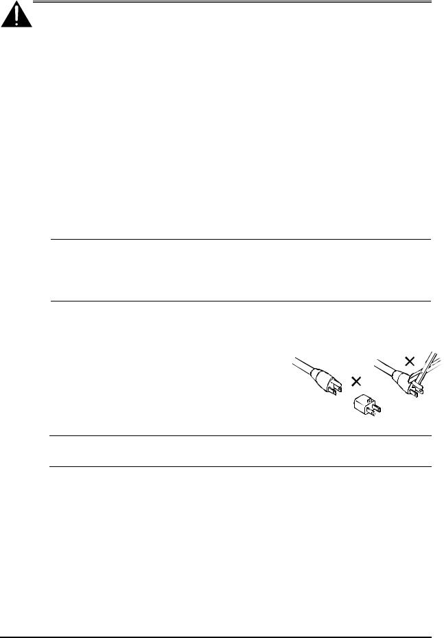
The ground terminal of the power plug is connected directly to the chassis of the unit. For continued protection against electric shock, a correctly wired and grounded (earthed) threepin power outlet must be used. Do not use a ground-lifting adapter and never cut the ground pin on the three-prong plug.
WARNING: Before applying power, check the main fuse, using the procedure on page ix.
UK
The power cord supplied for use in Europe (Dolby Part No. 92021) is not suitable for use in the UK. To use the cord in the UK cut off the CEE7/7 plug and replace with an approved BS 1363 13A plug:
•The core that is coloured green and yellow must be connected to the terminal in the
plug identified by the letter E or by the earth symbol  or coloured green or green and yellow.
•The core that is coloured blue must be connected to the terminal that is marked with the letter N or coloured black.
•The core that is coloured brown must be connected to the terminal that is marked with the letter L or coloured red.
•This apparatus must be earthed.
vii

DP564 Multichannel Audio Decoder
EU
This equipment complies with the EMC requirements of EN55103-1 and EN55103-2 when operated in an E2 environment in accordance with this manual.
IMPORTANT SAFETY NOTICE
This unit complies with the safety standard EN60065. The unit shall not be exposed to dripping or splashing and no objects filled with liquids, such as coffee cups, shall be placed on the equipment. To ensure safe operation and to guard against potential shock hazard or risk of fire, the following must be observed:
oEnsure that your mains supply is in the correct range for the input power requirement of the unit.
oEnsure fuses fitted are the correct rating and type as marked on the unit.
oThe unit must be earthed by connecting to a correctly wired and earthed power outlet.
oThe power cord supplied with this unit must be wired as follows:
Live—Brown Neutral—Blue Earth—Green/Yellow
IMPORTANT – NOTE DE SECURITE
Ce materiel est conforme à la norme EN60065. Ne pas exposer cet appareil aux éclaboussures ou aux gouttes de liquide. Ne pas poser d'objets |
||||
remplis de liquide, tels que des tasses de café, sur l'appareil. Pour vous assurer d'un fonctionnement sans danger et de prévenir |
|
|||
tout choc électrique ou tout risque d'incendie, veillez à observer les recommandations suivantes. |
F |
|||
o Le selecteur de tension doit être placé sur la valeur correspondante à votre alimentation réseau. |
||||
|
||||
o Les fusibles doivent correspondre à la valeur indiquée sur le materiel. |
|
|
||
o Le materiel doit être correctement relié à la terre. |
|
|
|
|
o Le cordon secteur livré avec le materiel doit être cablé de la manière suivante: |
|
|||
Phase—Brun |
Neutre—Bleu |
Terre—Vert/Jaune |
|
|
WICHTIGER SICHERHEITSHINWEIS
Dieses Gerät entspricht der Sicherheitsnorm EN60065. Das Gerät darf nicht mit Flüssigkeiten (Spritzwasser usw.) in Berührung kommen; stellen
Sie keine Gefäße, z.B. Kaffeetassen, auf das Gerät. Für das sichere Funktionieren des Gerätes und zur Unfallverhütung (elektrischer Schlag, |
||||
Feuer) sind die folgenden Regeln unbedingt einzuhalten: |
|
|
|
|
o Der Spannungswähler muß auf Ihre Netzspannung eingestellt sein. |
|
D |
||
o Die Sicherungen müssen in Typ und Stromwert mit den Angaben auf dem Gerät übereinstimmen. |
||||
|
||||
o Die Erdung des Gerätes muß über eine geerdete Steckdose gewährleistet sein. |
|
|
||
o Das mitgelieferte Netzkabel muß wie folgt verdrahtet werden: |
|
|
||
Phase—braun |
Nulleiter—blau |
Erde—grün/gelb |
|
|
NORME DI SICUREZZA – IMPORTANTE
Questa apparecchiatura è stata costruita in accordo alle norme di sicurezza EN60065. Il prodotto non deve essere sottoposto a schizzi, spruzzi e gocciolamenti, e nessun tipo di oggetto riempito con liquidi, come ad esempio tazze di caffè, deve essere appoggiato sul dispositivo. Per una perfetta sicurezza ed al fine di evitare eventuali rischi di scossa êlettrica o d'incendio vanno osservate le seguenti misure di sicurezza:
o |
Assicurarsi che il selettore di cambio tensione sia posizionato sul valore corretto. |
|
o |
Assicurarsi che la portata ed il tipo di fusibili siano quelli prescritti dalla casa costruttrice. |
I |
oL'apparecchiatura deve avere un collegamento di messa a terra ben eseguito; anche la connessione rete deve avere un collegamento a terra.
oIl cavo di alimentazione a corredo dell'apparecchiatura deve essere collegato come segue:
Filo tensione—Marrone Neutro—Blu Massa—Verde/Giallo
AVISO IMPORTANTE DE SEGURIDAD
Esta unidad cumple con la norma de seguridad EN60065. La unidad no debe ser expuesta a goteos o salpicaduras y no deben colocarse sobre el
equipo recipientes con liquidos, como tazas de cafe. Para asegurarse un funcionamiento seguro y prevenir cualquier posible peligro de descarga o |
||||
riesgo de incendio, se han de observar las siguientes precauciones: |
|
|
||
o Asegúrese que el selector de tensión esté ajustado a la tensión correcta para su alimentación. |
E |
|||
o Asegúrese que los fusibles colocados son del tipo y valor correctos, tal como se marca en la unidad. |
||||
|
||||
o La unidad debe ser puesta a tierra, conectándola a un conector de red correctamente cableado y puesto a tierra. |
|
|||
o El cable de red suministrado con esta unidad, debe ser cableado como sigue: |
|
|||
Vivo—Marrón |
Neutro—Azul |
Tierra—Verde/Amarillo |
|
|
VIKTIGA SÄKERHETSÅTGÄRDER!
Denna enhet uppfyller säkerhetsstandard EN60065. Enheten får ej utsättas för yttre åverkan samt föremål innehållande vätska, såsom
kaffemuggar, får ej placeras på utrustningen." För att garantera säkerheten och gardera mot eventuell elchock eller brandrisk, måste följande |
||||
observeras: |
|
|
|
|
o Kontrollera att spänningsväljaren är inställd på korrekt nätspänning. |
|
S |
||
o Konrollera att säkringarna är av rätt typ och för rätt strömstyrka så som anvisningarna på enheten föreskriver. |
||||
|
||||
o Enheten måste vara jordad genom anslutning till ett korrekt kopplat och jordat el-uttag. |
|
|||
o El-sladden som medföljer denna enhet måste kopplas enligt foljande: |
|
|
||
Fas—Brun |
Neutral—Blå |
Jord—Grön/Gul |
|
|
BELANGRIJK VEILIGHEIDS-VOORSCHRIFT:
Deze unit voldoet aan de EN60065 veiligheids-standaards. Dit apparaat mag niet worden blootgesteld aan vocht. Vanwege het risico dat er druppels in het apparaat vallen, dient u er geen vloeistoffen in bekers op te plaatsen. Voor een veilig gebruik en om het gevaar van electrische
schokken en het risico van brand te vermijden, dienen de volgende regels in acht te worden genomen: |
|
|
o |
Controleer of de spanningscaroussel op het juiste Voltage staat. |
NL |
o |
Gebruik alleen zekeringen van de aangegeven typen en waarden. |
|
oAansluiting van de unit alleen aan een geaarde wandcontactdoos.
oDe netkabel die met de unit wordt geleverd, moet als volgt worden aangesloten:
Fase—Bruin Nul—Blauw Aarde—Groen/Geel
viii

DP564 Multichannel Audio Decoder
Fusing Information
WARNING: To reduce the risk of fire, replace fuses only with the same type and rating.
The DP564 uses a universal switching power supply that handles the full range of nominal mains voltages between 90 and 264 VAC and any frequency between 50 and 60 Hz.
Main Fuse
The main fuse rating is:
T 1A L (1 amp, 250 V, 20 mm, time-lag, low breaking capacity) for all operating voltages.
The power cord must be removed from the rear-panel connection to inspect or replace the fuse.
To inspect or replace the main fuse:
1.Slide open the fuse compartment in the AC power input housing by placing the tip of a small screwdriver in the notch.
2.Carefully pull out the fuse carrier.
3.Either replace the fuse with a new one, or check that the current fuse has the correct rating.
4.Slide the fuse compartment back into place, then snap the fuse compartment closed.
Internal Fuse
The switching power supply contains a separate fuse. Most fault conditions should be protected by the main fuse.
If you find it necessary to replace the internal fuse, be certain to replace it with a fuse of the same type and rating as printed on the switching power supply board.
ix

DP564 Multichannel Audio Decoder
Chapter 1
Introduction
The DP564 Multichannel Audio Decoder gives studio professionals unparalleled ability to monitor different audio programs in a variety of listening modes.
Critical monitoring is essential to ensure that the highest quality audio reaches your listeners at home. The DP564 Multichannel Audio Decoder, the next generation reference decoder from Dolby Laboratories, is the perfect tool for monitoring and quality control applications in DTV broadcast, postproduction, and DVD authoring.
The DP564 enables decoding and monitoring of programs with Dolby® Digital, Dolby Surround Pro Logic®, or regular PCM soundtracks, as well as Dolby Digital Surround EX™ and Pro Logic II decoding, making the DP564 the ideal digital reference decoder for both Dolby Digital and Dolby Surround audio.
With the DP564, you can easily monitor all of Dolby Digital’s unique downmixing capabilities. This means content producers and providers can verify how material delivered in a 5.1-channel format will sound on systems that offer only Dolby Surround, two-channel stereo, or mono playback.
By switching between listening modes using the front-panel controls, it is possible to monitor how any multichannel program will sound when played on fully configured multichannel surround systems, as well as surround systems with no Center channel (Phantom) or even systems with no Surrounds (3 Stereo). Compression modes can also be selected from the front panel to easily monitor Dolby Digital’s dynamic range control and dialogue normalization features. These features are tailored to professional users to allow you to hear how your audio will sound on any set-top box, DVD player, or home theater receiver.
To set up and control the monitoring environment, the DP564 offers comprehensive monitoring functions—including a master volume knob on the front panel, channel mutes, reference monitoring level, individual channel level trims, center and surround channel delays, bass management, and both full and band-limited pink noise for quick and accurate room calibration. The headphone output has its own volume control, as well as Dolby Headphone processing, which provides surround sound monitoring over standard headphones. This allows more accurate QC monitoring and reduced listener fatigue for headphone listeners.
Figure 1-1 shows the DP564 system block diagram.
1-1

DP564 Multichannel Audio Decoder |
Introduction |
|
|
|
|
Note: The processing sequence is not identical to that of a consumer decoder. To efficiently deliver all the available features, downmixing is separated from the decoding block.
Timecode Output
|
|
|
|
|
|
|
|
|
None, RF, Line, |
|
|
|
|
|
|
|
|
|
|
|
|
Custom |
|
LoRo / LtRt |
|
|
|
|
|
|
|
|
|
|
Cut scaling |
LFE Monitor Mode: |
||
|
|
|
|
|
|
|
|
|
Boost scaling |
|
Auto / On / Off |
|
AES1 |
|
|
|
|
|
|
|
|
||||
(AES3 BNC) |
Dolby |
|
|
|
|
|
||||||
|
|
|
|
|
|
Compression |
|
Decoder |
|
|||
|
|
|
Dolby |
Digital |
|
|
|
|||||
|
|
|
Digital |
|
Selection |
|
Downmix |
|
||||
|
|
|
Decoder |
|
|
|
||||||
|
|
|
|
|
|
|
|
|
|
|||
|
|
|
LDEC |
CDEC |
LsDEC |
LFEDEC |
|
|
|
RDEC |
RsDEC |
||
AES2 |
|
|
|
|
||
|
LPCM |
|
|
|
|
|
(AES3 BNC) |
|
|
|
|
|
|
|
|
RPCM |
|
|
|
|
Input Select |
Bitstream |
PCM |
|
|
|
|
Detect |
|
|
|
|
||
|
|
Mono |
|
|
|
|
|
|
On / Off |
|
|
|
|
Optical |
|
Sum |
|
|
|
|
|
|
|
|
|
||
(TOSLINK) |
|
|
|
|
|
|
|
|
|
|
|
|
|
|
On / Off |
|
Pro Logic |
|
|
|
|
|
|
|
|
|
|
||||
|
|
|
|
|
|
|
|
Manual / Auto |
|
Decode |
|
|
|
|
|
|
|
|
|
|
||||
|
|
|
|
|
|
|
|
Pro Logic/ Pro Logic II |
|
|
|
|
|
|
|
|
|
|
|
|||||
Streaming |
|
|
|
|
|
|
|
|
|
|
|
|
|
|
|
|
|
|
|
|
|
|
|
|
|
|
|
|
|
|
|
|
|
|
|
|
|
|
|
|
|
|
|
|
|
|
|
||
(RTP 100BASE-T) |
|
|
|
|
|
|
|
|
|
|
|
|
|
|
|
|
|
|
|
|
|
|
|
|
|
|
|
|
|
|
|
|
|
|
|
|
|
|
|
|
|
|
|
|
|
|
|
|
|
|
|
|
|
|
|
|
|
|
|
|
|
|
|
|
|
|
|
|
|
|
|
|
|
|
|
|
|
|
|
|
|
|
C speaker On/Off |
|
|
|
|
Listening Modes |
|
|
|
|
|
|
|||||
|
|
|
|
|
|
|
|
S speakers On/Off |
|
|
|
|
|
|
|
|
|
|
||||||
|
|
|
|
|
|
|
|
|
|
|
|
|
|
|
|
|
|
|
|
|
|
|||
|
|
|
|
|
|
|
|
|
|
|
|
|
|
|
|
|
|
|
|
|
|
|
||
|
|
|
|
|
|
|
|
|
|
|
|
LLM |
|
CLM |
Ls |
|
|
|
||||||
|
|
|
|
|
|
|
|
|
|
|
|
RLM |
|
LsLM |
|
|
|
|||||||
|
|
|
|
|
|
|
|
|
|
|
|
|
|
|
|
|
|
|
LM |
|
|
|
||
DH1, DH2, DH3, or |
Dolby Headphone |
|
|
|
|
|
|
|
|
|
|
|
|
|
|
|
|
|
|
|
||||
Off (stereo bypass) |
|
Processor |
|
|
|
|
|
|
|
|
|
|
|
|
|
|
|
|
|
|
|
|||
|
|
|
|
|
|
|
|
|
|
|
|
|
|
|
|
|
|
|
|
|
|
|
|
|
|
|
|
|
|
|
|
|
|
|
|
|
|
|
|
|
|
|
|
|
|
|
|
|
|
|
|
|
|
|
|
|
|
|
L/R Large/Small |
|
|
|
|
|
|
|
|
|
|
|
|
|
|
|
|
|
|
|
|
|
|
|
|
C Large/Small |
|
|
|
|
|
Bass Management |
|
|
|
||||||
|
|
|
|
|
|
|
|
|
S Large/Small |
|
|
|
|
|
|
|
|
|||||||
|
|
|
|
|
|
|
|
|
|
|
|
|
|
|
|
|
|
|
|
|
|
|
||
|
|
|
|
|
|
|
|
|
SW On/Off |
|
|
|
|
|
|
|
|
|
|
|
|
|
|
|
|
|
|
|
|
|
|
|
|
|
|
|
|
|
|
|
|
|
|
|
|
||||
|
|
|
|
|
|
|
|
|
|
|
|
LBM |
|
CBM |
LsBM |
|
SWBM |
|||||||
|
|
|
|
|
|
|
|
|
|
|
|
RBM |
|
RsBM |
|
|||||||||
|
|
|
|
|
|
|
Bypass |
|
|
|
|
|
|
Manual / Auto |
||||||||||
|
|
|
|
|
|
|
|
|
|
|
|
|
|
|
|
|
|
|
Dolby |
|
|
On / Off |
||
|
|
|
|
|
|
|
|
|
|
|
|
|
|
|
|
|
|
|
|
|
|
|||
|
|
|
|
|
|
|
|
|
|
|
|
|
|
|
|
|
|
|
Surround EX |
|
|
|
||
|
|
|
|
|
|
|
|
|
|
|
|
|
|
|
|
|
|
|
Decoder |
|
|
|
||
|
|
|
|
|
|
|
|
|
|
|
|
|
|
|
|
|
|
|
|
|
|
|
|
|
|
|
|
|
|
|
|
|
|
|
|
|
|
|
|
|
|
|
|
LsEX,RsEX |
|
|
|
||
|
|
|
|
|
|
|
|
|
|
|
|
|
|
|
|
|
|
|
BsEX |
|
SW |
|||
|
|
|
|
|
|
|
|
|
L/R Delay |
|
|
|
|
Speaker Delays |
|
|
|
|
|
|
||||
|
|
|
|
|
|
|
|
|
C Delay |
|
|
|
|
|
|
|
|
|
|
|||||
|
|
|
|
|
|
|
|
|
LsRs Delay |
|
|
|
|
L/R, C, Ls/Rs, Bs |
|
|
|
|
|
|
||||
|
|
|
LDH |
|
|
|
Bs Delay |
|
|
|
|
|
|
|
|
|
|
|
|
|
|
|||
|
|
|
RDH |
|
|
Test Noise |
|
|
|
L |
|
|
|
|
|
|
LsSD,RsSD |
|
|
|
||||
|
|
|
|
|
|
|
|
SD |
|
CSD |
BsSD |
|
|
None / 1 / 2 |
||||||||||
|
|
|
|
|
|
|
|
|
|
|
|
RSD |
|
|
|
|
|
|
|
|
|
|
||
|
|
|
|
|
|
|
|
|
|
|
|
|
|
|
|
Bs Speaker |
|
|
|
|||||
|
|
|
|
|
|
|
|
|
|
|
|
|
|
|
|
|
|
|
|
|
|
|||
|
|
|
|
|
|
|
|
|
|
|
|
|
|
|
|
|
|
|
Split |
|
|
|
||
|
|
|
|
|
|
|
|
|
|
|
|
|
|
|
|
|
|
|
|
|
|
|
||
|
|
|
|
|
|
|
|
|
|
|
|
|
|
|
|
|
|
|
LsSS,RsSS |
|
|
|
||
|
|
|
IFE |
|
|
|
|
|
|
|
|
|
|
|
|
|
BslSS,BsrSS |
|
|
|
||||
|
|
|
Mode |
|
|
|
|
|
|
|
|
|
|
|
|
|
|
|
|
|
|
|||
|
|
|
|
|
|
|
|
|
|
Output Select |
|
|
|
|
|
|
|
|
|
|
||||
|
|
|
|
|
|
|
|
|
|
|
|
|
|
|
|
|
|
|
|
|
|
|
|
|
|
|
|
|
|
|
|
|
|
|
|
|
|
|
|
|
|
|
|
|
|
|
|
|
|
|
|
|
|
|
|
|
|
|
|
|
|
|
|
|
|
D/A |
|
|
Level |
|
Analogue Output |
|||
|
|
|
|
|
|
|
|
|
|
|
|
|
|
|
|
|
|
|||||||
|
|
|
D/A |
|
|
|
|
|
|
|
|
|
|
|
|
Control |
|
|||||||
|
|
|
|
|
|
|
|
|
|
|
|
|
|
|
|
|
|
|
|
|
||||
|
|
|
|
|
|
|
|
|
|
|
|
|
|
|
|
|
|
|
|
|
|
|
||
|
|
|
|
|
|
|
|
|
|
|
|
|
|
|
|
|
|
|
|
|
|
|||
|
|
|
|
|
|
|
|
|
|
|
|
|
|
|
|
|
Master Volume Control, |
|
|
|||||
|
|
|
|
|
|
|
|
|
|
|
|
|
|
|
|
|
Channel Trims, and Dim |
|
|
|||||
|
|
|
|
|
|
Front-Panel |
|
|
|
|
Optional |
|
|
|
|
|
|
|
||||||
|
|
|
Volume |
|
|
|
|
|
|
Level |
|
|
|
|
|
|
Digital Output |
|||||||
|
|
|
|
Headphone Volume |
|
|
|
|
|
|
|
|
|
|
||||||||||
|
|
|
Control |
|
|
|
|
|
|
Control |
|
|
|
|
|
|
|
|
||||||
|
|
|
|
|
Control |
|
|
|
|
|
|
|
|
|
|
|
|
|||||||
|
|
|
|
|
|
|
|
|
|
|
|
|
|
|
|
|
|
|
|
|
|
|
|
|
|
|
|
|
|
|
|
|
|
|
|
|
|
|
|
|
|
|
|
|
|
|
|
|
|
|
|
|
Headphone |
|
|
|
|
|
|
|
|
|
|
|
|
|
|
|
|
|
Headphone Output |
|||
|
|
|
|
|
|
|
|
|
|
|
|
|
|
|
|
|
|
|
|
|||||
|
|
|
Amplifier |
|
|
|
|
|
|
|
|
|
|
|
|
|
|
|
|
|
||||
|
|
|
|
|
|
|
|
|
|
|
|
|
|
|
|
|
|
|
|
|
|
|
|
|
|
|
|
|
|
|
|
|
|
|
|
|
|
|
|
|
|
|
|
|
|
|
|
|
|
1-2

DP564 Multichannel Audio Decoder |
Introduction |
|
|
|
|
Figure 1-1 DP564 System Block Diagram
The 2-U rack-mount unit features multiple inputs including two AES3 inputs, a Toslink optical input, and an Ethernet port for RTP-streaming Dolby Digital audio. The inputs are easily selected with dedicated front-panel buttons.
The front panel also incorporates a display screen, featuring high contrast and a wide viewing angle. In addition to providing an intuitive interface for menu access and setup, the display is easy to read and offers clear graphic status menus for all Dolby Digital metadata settings and metering of output levels and dynamic range control.
The rear panel includes the main audio output connections for both digital AES3 and analog +4 dBu balanced outputs. A linear timecode (LTC) output generates timecode from a Dolby Digital bitstream, allowing DVD facilities to check A/V sync between encoded Dolby Digital audio files and uncompressed video. Frontand rear-panel serial interfaces and an Ethernet port enable remote control and software updates; a remote control software application is included to configure and control the DP564 from a PC via Ethernet or serial connection. Remote control is also possible from an optional dedicated hardware controller—either the Dolby Cat. No. 549 GPIO Controller or another system using the general-purpose I/O connector (GP I/O).
1-3

DP564 Multichannel Audio Decoder
Chapter 2
Installation
This chapter covers the physical connections necessary to operate the DP564.
2.1Mounting
The DP564 occupies 2U of rack space. The unit operates at ambient temperatures up to 122° F (50° C) and vents from front to rear.
Caution: Do not mount the DP564 directly above heat-generating equipment. Ensure adequate ventilation. The temperature inside a poorly ventilated rack can be considerably higher than ambient room temperature.
2.2Rear-Panel Connections
The rear-panel connections include BNC inputs and outputs, an optical input, serial ports, analog audio outputs, and the power supply. It is best to make all other connections before connecting the power supply.
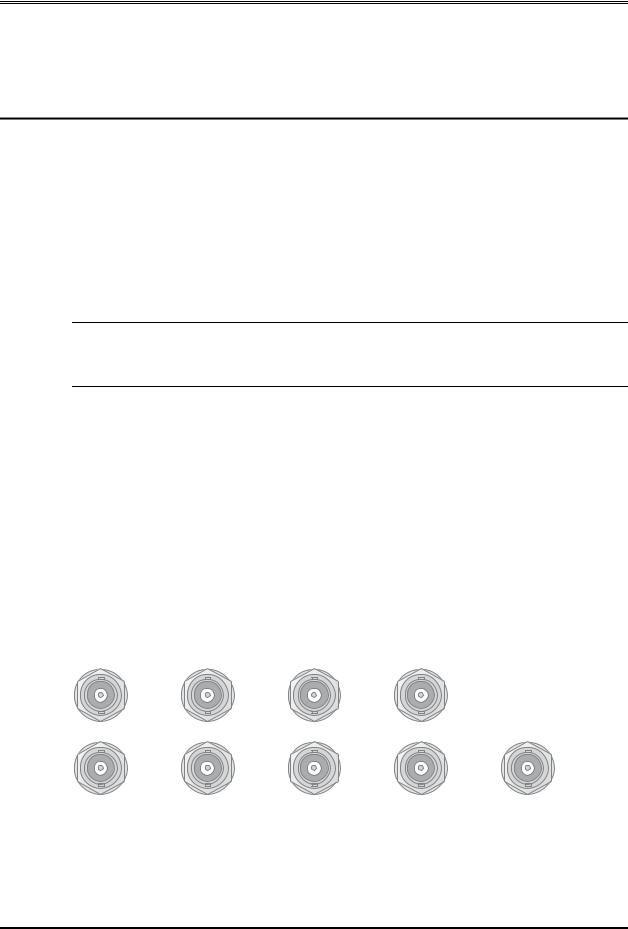
2.2.1BNC Connectors
Figure 2-1 shows the BNC connectors. These are compliant with the AES3-ID standard.
AES 1 Digital In AES 2 |
LTC Out |
AES Ref |
L/R |
|
C/Sw Digital Out Ls/Rs |
|
Bsl/Bsr |
|
|
Figure 2-1 Connection Ports for Digital Signals
The AES Ref connectors are for an AES3 external reference. Connect an AES3 reference signal to either port. The other connector may be used to pass the reference
2-1
DP564 Multichannel Audio Decoder |
Installation |
|
|
|
|
signal on to another unit; if pass-through is not necessary, this connector should be fitted with a 75-ohm terminator.
The Digital In connectors, AES 1 and AES 2, can receive both Dolby® Digital and PCM signals. The decoder recognizes each signal type and processes the signal appropriately. Digital inputs can also be received using the Optical In and 100BASE-T inputs shown in Figure 2-2.
The LTC Out connector provides a SMPTE 12M linear timecode output signal. Timecode is extracted from the timestamp embedded in a SMPTE 337M bitstream that may be present in a Dolby Digital signal.
The Digital Out connectors provide a digital output signal for connection to a digital monitoring system. Each connector is labeled according to the channel pair it contains.
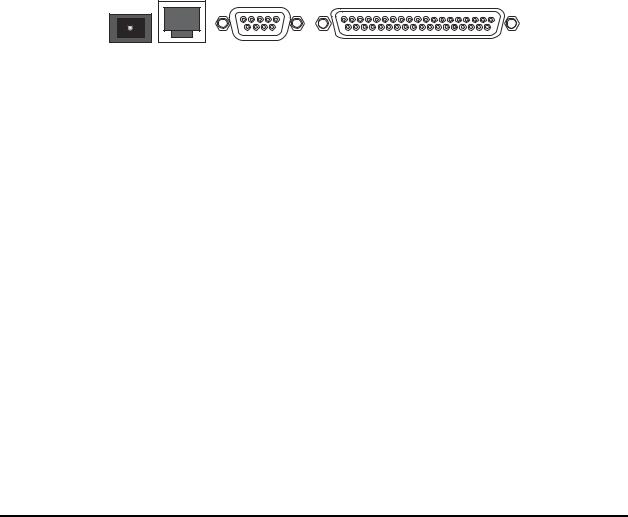
2.2.2Optical In and Serial Ports
Figure 2-2 shows the Optical In and the serial connections.
|
|
19 |
|
1 |
Optical In 100BASE-T |
Remote RS-485 |
37 |
GP I/O |
20 |
|
|
|
||
|
|
|
|
Figure 2-2 Connection Ports for Optical, Ethernet, Remote, and GPI/O
The Optical In connection can receive both Dolby Digital and PCM signals. The decoder recognizes each signal type and processes the signal appropriately.
The 100BASE-T port can connect to a 100Base-T or 10Base-T network. The connection can then be used for streaming audio, and to enable the DolbyRemote 564 remote control application. See Chapter 8, Streaming Server and Remote Software, for details.
The Remote RS-485 port can connect to a computer running DolbyRemote 564. The DolbyRemote 564 application is far more efficient, however, when connected via the 100BASE-T port. For details, see Chapter 8, Streaming Server and Remote Software.
The GP I/O port connects to the Dolby Cat. No. 549 GPIO Controller (sold separately) or to a separate remote control device, which must be configured according to the pinout information under GPI/O Configuration in Section 4.4.4, I/O Control.
2-2

DP564 Multichannel Audio Decoder |
Installation |
|
|
|
|
2.2.3Analog Outputs
The +4 dBu balanced Analog Audio Outputs connect directly to your monitoring system. Each connector is labeled according to the channel signal it sends.
If your system includes a single speaker for Back Surround, use only the Bsl output, and leave the Bsr output open.
2.2.4Power
The main fuse rating is:
T 1A L (1 amp, 250 V, 20 mm, time-lag, low breaking capacity) for all operating voltages.
WARNING: Before applying power, check the main fuse using the procedure on page ix.
There is no power switch on the DP564. To apply power, connect the power cord to a live outlet.
2-3


DP564 Multichannel Audio Decoder
Chapter 3
Front-Panel Controls
Every function of the DP564, except control of streaming audio, is accessible using the front-panel buttons in combination with the information on the display screen. This chapter covers
•Front-panel layout
•Button functions
•LED indicators
•The RS-232 connection
Streaming audio can be controlled using the DolbyRemote 564 software. See Chapter 8, Streaming Server and Remote Software, for details.
3.1Front-Panel Layout
The left-hand side of the front panel includes the screen display and LED indicators. The screen displays information on the current status, or setup menus that you navigate using the buttons described in Section 3.2, Button Functions. The LED indicators are defined in Section 3.3, LED Indicators.
The front-panel controls are shown in Figure 3-1.
Shift
e t o m
e R
Bypass Status
Esc Setup
|
B |
|
r |
|
i |
|
g |
Enter |
h |
t |
|
|
n |
|
e |
|
s |
|
s |
Navigation |
Listening |
|
|
|
Mode |
Pro Logic II |
Full |
Custom |
Stereo |
|
|
(Lo/Ro) |
|
|
Mono Pro Logic |
3 Stereo |
Line |
Lt/Rt |
|
|
EX |
Phantom |
RF |
Downmix |
Decode |
Listening |
Compression |
Output Level
AES1 |
1 |
Ref |
Dim |
AES2 2
Optical 3
Streaming 4
Input |
Preset |
Master Volume |
|
|
Remote
RS-232
Figure 3-1 Front-Panel Controls
The navigation buttons control selection of menu items on the screen display. The listening mode buttons are for selection of specific monitoring configurations. This allows monitoring of a program in all the different ways a consumer may listen to it. The Input buttons are for choosing the source for the DP564. Preset buttons are for
3-1

DP564 Multichannel Audio Decoder |
Front-Panel Controls |
|
|
|
|
one-touch recall of a complete set of parameter settings previously stored as a preset. Output-level controls set the volume level for your listening environment. Detailed explanations of each button function follow.
3.2Button Functions
Each button on the front panel controls a function or functions in the DP564. These functions are defined in this section.
Any time a feature is active, the front-panel button associated with that feature is lit. This is true whether the feature is activated or deactivated manually, or controlled by program metadata, GPI/O, or a preset configuration.
3.2.1Navigation
Shift
Bypass
Esc
Enter
Status
Setup
The primary function of each button in this group is printed on the button. To perform the alternate function (printed on the panel above or beside the button in yellow text), press Shift, then the button associated with the desired function. When you press Shift, that button stays lit until you press another button, or press Shift again to disable the alternate-function selection.
In this group of buttons, there is one function that goes beyond navigation: Bypass. If the DP564 receives a PCM signal while in bypass mode, it passes the signal straight to the Left and Right channel outputs with no processing. If the DP564 receives a Dolby® Digital signal, it decodes the signal, but all further processing is disabled. This includes dialogue normalization, dynamic range control, and downmixing, as well as all surround formats, bass management, and channel delays. Channel level trims and master volume continue to function. When you select Bypass (Shift, then Esc), bypass mode remains in effect until you disable it by using the same button combination. When you disable bypass mode, the unit returns to the settings in effect when you entered bypass mode.
The navigation buttons work in combination with the display screen menus. In setup menu screens and the Metadata Status, Error Status, and System Status screens, pressing Enter enters the submenu for the highlighted selection, and pressing Esc returns to the next higher menu level. If you are at the top of a menu structure, Esc has no effect. If you change a value for a parameter in the setup menu, Enter activates the new value and returns to the next higher menu level, and Esc discards the new value and returns to the next higher menu level. For details on menu structure, see Chapter 4, Menus.
The default menu at startup is the status menu. The status and setup menus have separate functions and structures, detailed in Chapter 4, Menus. If you are in a status menu, Setup changes the display to a setup menu. If you used the setup menu within the previous five minutes, it returns you to the last setup menu you saw. If you have not used a setup menu within that time, pressing Setup displays the top-level setup
3-2
DP564 Multichannel Audio Decoder |
Front-Panel Controls |
|
|
|
|
B
r
i g
h t n e ss
e t o m
e R
menu. If you are in a setup menu, Status changes the display to a status menu. If you are in a setup menu, Setup brings up the top-level setup menu. If you are in a status menu, Status brings up the main status menu.
▲ moves the item selection in the display to the next item up. In the setup menu, if the current menu designates a numerical value, ▲ increases the value to the next higher increment.
► navigates within and between menus. In the setup menu, ► enters that item’s submenu, unless there is no submenu. In the status menu, ► scrolls to the next available menu. Brightness takes you directly to the menu where you can adjust the intensity of the display.
▼ moves the item selection in the display to the next item down. In the setup menu, if the current menu designates a numerical value, ▼ decreases the value to the next lower increment.
◄ navigates between menus. In a multi-layer menu, ◄ returns to the next-higher menu (same as Esc). In the top-level status menu, ◄ scrolls to the adjacent menu, (in the opposite scrolling direction as ►). Remote invokes remote control by the DolbyRemote 564 software. When the DP564 is under remote control, Remote ends remote control and re-activates all front-panel controls.
Note: When the DP564 is under remote control, most front-panel controls are inactive. In this mode, the Master Volume knob is active, and you can scroll through the status menus, or press Remote, which ends remote control and reactivates all front-panel controls.
3.2.2Listening Modes
Stereo (Lo/Ro)
Lt/Rt
Mono
By reproducing the wide variety of consumer listening environments, listening mode selections enable you to make sure the audio program is optimized for every listening situation. The selections are divided into four categories: Downmix, Decode,
Listening, and Compression.
Downmix
Use the Downmix buttons to select the downmix you monitor. Lo/Ro downmixes to a stereo output. Lt/Rt downmixes to a Dolby Surround Pro Logic® compatible stereo output. Lo/Ro and Lt/Rt are unavailable if the Dolby Digital input signal is in audio coding mode 2/0, 1/0, or if the input signal is PCM.
Mono summing is available only if the input is PCM, a Dolby Digital signal in audio coding mode 2/0, or any other Dolby Digital signal downmixed to Lt/Rt or Lo/Ro.
3-3

DP564 Multichannel Audio Decoder |
Front-Panel Controls |
|
|
|
|
Pro Logic II
Pro Logic
EX
Decode
Use the Decode buttons to select a specific surround-decoding mode.
Note: Dolby Digital decoding is applied whenever a Dolby Digital signal is received. The Decode buttons offer additional processing options.
EX activates Dolby Digital Surround EX™ decoding. It is available only when decoding Dolby Digital bitstreams with stereo surround channels. You must also have back surround (Bsl, Bsr) speakers selected in the Monitor Configuration menu. Pro Logic and Pro Logic II activate those decoding modes, respectively. The Pro Logic modes are available only if the input is PCM, a Dolby Digital signal in audio coding mode 2/0, or any other Dolby Digital signal downmixed to Lt/Rt.
Full
3 Stereo
Phantom
Custom
Line
RF
Note: To quickly access the display screen to adjust Pro Logic II settings, hold down the Pro Logic II button for two seconds.
Listening
Use the Listening buttons to simulate different consumer multichannel speaker systems. Phantom mixes the Center channel signal to the Left and Right channel outputs to emulate a speaker system with no center channel. 3 Stereo mixes the Ls and Rs channel signals to the front-channel outputs to emulate speaker systems with no surround speakers. (Ls routes to L, and Rs routes to R.) Full maps all channel signals directly to the associated outputs. Only one of these modes is active at a time.
Compression
The Compression buttons can apply the dynamic range control profiles available to consumers when decoding Dolby Digital audio. Only one of these modes is active at a time; to disable compression, press the active button.
RF applies the strongest profile available, equivalent to an RF connection to a TV set or small PC speakers. Line applies what appears on some consumer decoders as “light” compression; this is usually the default setting in DVD players and set-top boxes. Custom allows scaling of the Line profile. The factory setting for Custom is 0 percent. At that setting, selecting Custom turns off dynamic range compression. To access the display screen to adjust the percentage setting for custom scaling, hold down Custom for two seconds.
Note: When downmixing, the DP564 automatically applies compression at peak moments to prevent potential signal overload from combining multiple channels, regardless of whether a compression mode is selected.
3-4

DP564 Multichannel Audio Decoder |
Front-Panel Controls |
|
|
|
|
3.2.3Input
Use the Input buttons to select the source for the input signal. Only one of these buttons is lit at a time, indicating the selected source: AES1, AES2, Optical, or Streaming. If the selected source receives an invalid signal, the Error LED turns red.
3.2.4Preset
Preset buttons 1, 2, 3, and 4 recall and store those preset configurations. To recall any one of those presets, press the associated button and release the button quickly. To store the current configuration as one of those four presets, pick a preset button and hold it down for two seconds or more before releasing. This saves the current configuration and keeps the existing preset name. To rename the preset, use the menus as described in Section 4.4.3, User Presets.
Caution: When recalling presets 1–4 by pressing the Preset buttons, you must release the button in less than two seconds, or that preset will reconfigure to store the current settings.
When you recall preset 1, 2, 3, or 4, the associated button is lit. When you alter any parameter setting, the button light turns off, because the configuration is no longer that of the preset.
3.2.5Output Level
You can control the DP564 output level with the Master Volume knob and the Ref and Dim buttons. The headphone output has its own dedicated volume-control knob. Rotate Master Volume to raise and lower the output level incrementally, within a range of –95 to +10 dB. Ref resets the output level to 0 dB at one touch. Any time the output level is 0 dB, Ref is lit, whether the level was set via button or by Master Volume adjustment. Dim adjusts the output by the amount set in the Dim Gain menu, as discussed in Section 5.4, One-Touch Output Level Adjustment.
The headphone output volume knob controls the output level to the headphone jack only, and is not affected by Master Volume, Ref, or Dim.
When any adjustment is made to the master volume, the middle of the screen momentarily shows the current master volume level.
3-5

DP564 Multichannel Audio Decoder |
Front-Panel Controls |
|
|
|
|
3.2.6Special Button Functions
Under certain conditions, you may need to reset the DP564. Table 3-1 shows the button combinations to use in those cases.
|
Table 3-1 Special Button Functions |
|
|
|
|
Function |
|
Action; Result |
|
|
|
Hardware Reset |
|
Press Shift + Esc + ► simultaneously; the DP564 reboots. |
|
|
|
Firmware Upgrade |
|
During reboot, press and hold Setup; the status display |
|
|
gives you the option of upgrading the unit firmware or |
|
|
completing the boot sequence. |
Factory Reset |
|
During reboot, press and hold Enter; the status display |
|
|
gives you the option of restoring factory defaults or |
|
|
completing the boot sequence. |
|
|
Note: Restoring factory defaults includes all presets and |
|
|
GPI/O configuration assignments. |
3.3LED Indicators
Figure 3-2 shows the LED lights on the front panel. Table 3-2 provides definitions of the LED indicators.
|
|
|
|
Table 3-2 LED Status Definitions |
|
||
|
|
|
|
|
|
|
|
|
|
LED |
Status |
|
|
Meaning |
|
|
|
|
|
|
|
|
|
|
|
Dolby Digital |
Off |
|
|
Not decoding Dolby Digital. |
|
|
|
Blue |
|
|
Decoding Dolby Digital. |
|
|
|
|
|
|
|
|
||
Dolby Digital |
|
|
Off |
|
|
AES reference input is not selected. |
|
|
AES Ref |
Green |
|
|
AES reference input is selected and valid. |
|
|
|
|
|
|
|
|||
AES Ref |
|
|
Red |
|
|
AES reference input is selected but valid signal is not |
|
|
|
|
|
|
present. |
|
|
|
|
|
|
|
|
|
|
Remote |
|
|
Off |
|
|
Remote control is disabled. |
|
|
Remote |
Green |
|
|
Remote control is enabled and operating with no errors. |
|
|
|
|
|
|
|
|||
Fault |
|
|
Red |
|
|
Remote control is enabled, but there is a serial |
|
|
|
|
|
|
|
communications error. |
|
Error |
|
Fault |
Off |
|
|
All clear. |
|
|
|
Red |
|
Hardware error. |
|
||
|
|
|
|
|
|||
Figure 3-2 |
|
Error |
Off |
|
|
System is passing or decoding audio. |
|
|
Red |
|
|
An error is preventing the system from passing or |
|
||
LED Indicators |
|
|
|
|
|
||
|
|
|
|
|
|
decoding; DP564 output may be muted. |
|
3-6

DP564 Multichannel Audio Decoder |
Front-Panel Controls |
|
|
|
|
3.4RS-232 Connection
The Remote RS-232 connection port can be used to connect for software updates, or to a computer running DolbyRemote 564. The DolbyRemote 564 application is far more efficient, however, when connected via the 100BASE-T port. For details, see Chapter 8, Streaming Server and Remote Software.
3-7


DP564 Multichannel Audio Decoder
Chapter 4
Menus
Much of the versatility and power of the DP564 lies in its menu structure. This chapter covers:
•Menu basics
•Hot-key function
•Status menu
•Setup menu
4.1Menu Basics
The screen shows information on the current operating status via the status menu, and lets you adjust operational settings using the setup menu. In either menu structure, the title of a menu appears centered above a line at the top of the screen, and information or menu choices display below the line, as shown in the example in Figure 4-1.
Operating Mode
Decode |
Format |
Auto |
Detection |
Normal |
|
Stream |
Select |
Auto |
AES3 Ch Sel |
Auto |
|
Figure 4-1 Operating Mode Menu
In a menu with more options than lines available on the screen, an arrow appears in the title bar to indicate that you can see more by scrolling up or down past the visible items. If menu items are available both above and below the current display, the title bar displays both up and down arrows, as shown in Figure 4-2.
Metadata Status
LFE Ch |
Enabled |
Data Rate |
448 kbps |
BSMode |
Main Comp |
Center Dwnmx |
–3.0dB |
Srnd Dwnmx |
–3.0dB |
Dolby Srnd |
Not Ind |
Figure 4-2 Menu Showing Scrolling Options Available Both Above and Below Current Visible Choices
4-1

DP564 Multichannel Audio Decoder |
Menus |
|
|
|
|
4.2Hot-Key Functions
Certain front-panel buttons activate a special function when you press and hold the button for two seconds. We refer to that function as the hot-key function.
No matter what menu you are viewing, there are three front-panel buttons that display the setup menu for that function when you press and hold the button for two seconds: Pro Logic II, Custom, and Dim. Holding Custom down is the only way to define the parameters for custom compression scaling using the front-panel controls, but those parameters are also adjustable using the DolbyRemote 564 software.
The Preset buttons have a different hot-key function. Holding down any Preset button for two seconds saves the current configuration but keeps the existing preset name. To rename the preset, use the menus as described in Section 4.4.3, User Presets.
Caution: When recalling presets 1–4 by pressing the Preset buttons, you must release the button in less than two seconds, or that preset will reconfigure to store the current settings.
4.3Status Menu
The status menu includes these displays:
•Main status menu
•Output level meters
•Compression meters
•Monitor status
•Metadata status
•Input status
•AES reference input status
•Timecode status
•Error Statistics
•System Status
4.3.1Main Status Menu
At power-up, the DP564 displays the main status menu. If there is no valid input, the main status screen shows No Input.
4-2

DP564 Multichannel Audio Decoder |
Menus |
|
|
|
|
If the selected input is receiving a valid Dolby® Digital signal, the display conveys important information about the input stream and the decoding status, as shown in Figure 4-3.
Dolby Digital |
|
Dialog |
48kHz |
|
|
448 |
Level |
|
Data Rate |
-27 |
|
Chan Mode |
3/2L |
|
00:00:00:00 |
|
29ND |
|
|
PL EX |
Preset 1 |
|
EB DH |
|
|
|
Figure 4-3 Main Status Menu with a Valid Dolby Digital Input
The main box displays the type of input, sample rate, data rate (in kbps), channel mode, and timecode. Dialogue level displays in the upper right-hand corner.
Timecode information displays according to the option selected in the Timecode Display menu. Timecode information continually updates with the input signal. In the display mode shown here, the timecode display is hours:minutes:seconds:frames. 29 indicates the frame rate—in this case, 29.97 fps. ND indicates non-drop frame status. In a drop-frame condition, those letters read DF, and semicolons separate the timecode units: hours;minutes;seconds;frames. Other options for the timecode information in the main status menu are the timestamp delay word, or blank. Complete timecode information is always available in the Timecode Status menu.
If a preset is in use, the preset number and name display in the bottom left-hand corner. On the right-hand side, any of the four abbreviations shown in Figure 4-3 may appear—these indicate metadata parameters in the Dolby Digital stream. All four will never appear together, as they do in Figure 4-3, because some of those bitstreams are mutually exclusive. The abbreviations are:
•PL (indicating a 2/0 bitstream is flagged “Dolby Surround encoded”)
•EX (indicating a 5.1, 5.0, or 2/2 bitstream is flagged “Dolby Surround EX™ encoded”)
•EB (indicating a bitstream includes extended bitstream information)
•DH (indicating a 2/0 bitstream is flagged as a pre-encoded Dolby Headphone mix)
If there is a valid PCM signal, the display appears as shown in Figure 4-4.
4-3

DP564 Multichannel Audio Decoder |
Menus |
|
|
|
|
PCM Audio 44.1 kHz
20 Bit
Consumer
Preset 1
Figure 4-4 Main Status Menu with a Valid PCM Input
The space above the line displays the type of input, sample rate, bit depth, and mode (Professional or Consumer) of the stream. The DP564 accepts inputs up to 96 kHz, downsampling higher sample rates for processing at 48 or 44.1 kHz. Below
the line, you can still see the preset name and number, but the two-letter abbreviations do not apply to a PCM stream.
4.3.2Output Level Meters
The output level meters screen displays the level of each audio output signal after all decoding, downmix, listening-mode, compression-mode, and bass-management signal processing, but before any channel-level trims or delays.
4.3.3Compression Meters
The compression meters give a clear visual representation of the way in which the dynamic range control is working on a Dolby Digital program. This display shows dynamic range activity for both Line and RF profiles regardless of your Compression selection. This screen also shows the current dialogue level value in the Dolby Digital bitstream.
4.3.4Monitor Status
The Monitor Status menu shows the settings for your current monitor setup, including speaker configuration, subwoofer presence, crossover frequency (for bass management), extended bitstream emulation status, and headphone output mode (stereo or Dolby Headphone profile).
4.3.5Metadata Status
The Metadata Status menu displays the settings for metadata parameters received in the Dolby Digital bitstream. Use ▲ or ▼ to select any parameter, and Enter to view the unabbreviated parameter name and status. You can view extended bitstream parameter status by scrolling to the bottom of the Metadata Status menu to select Extended Bitstream, then pressing Enter. For more information about Dolby metadata, see Appendix A, Dolby Metadata.
4-4
 Loading...