

Page 1
Operation Manual
Fiber-Lite
®
TM
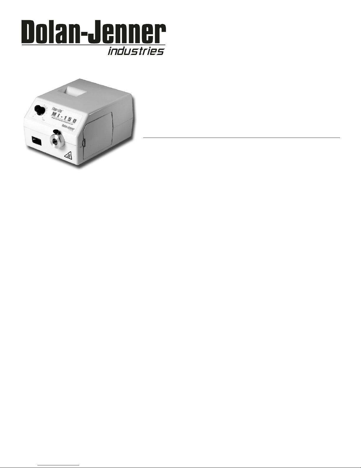
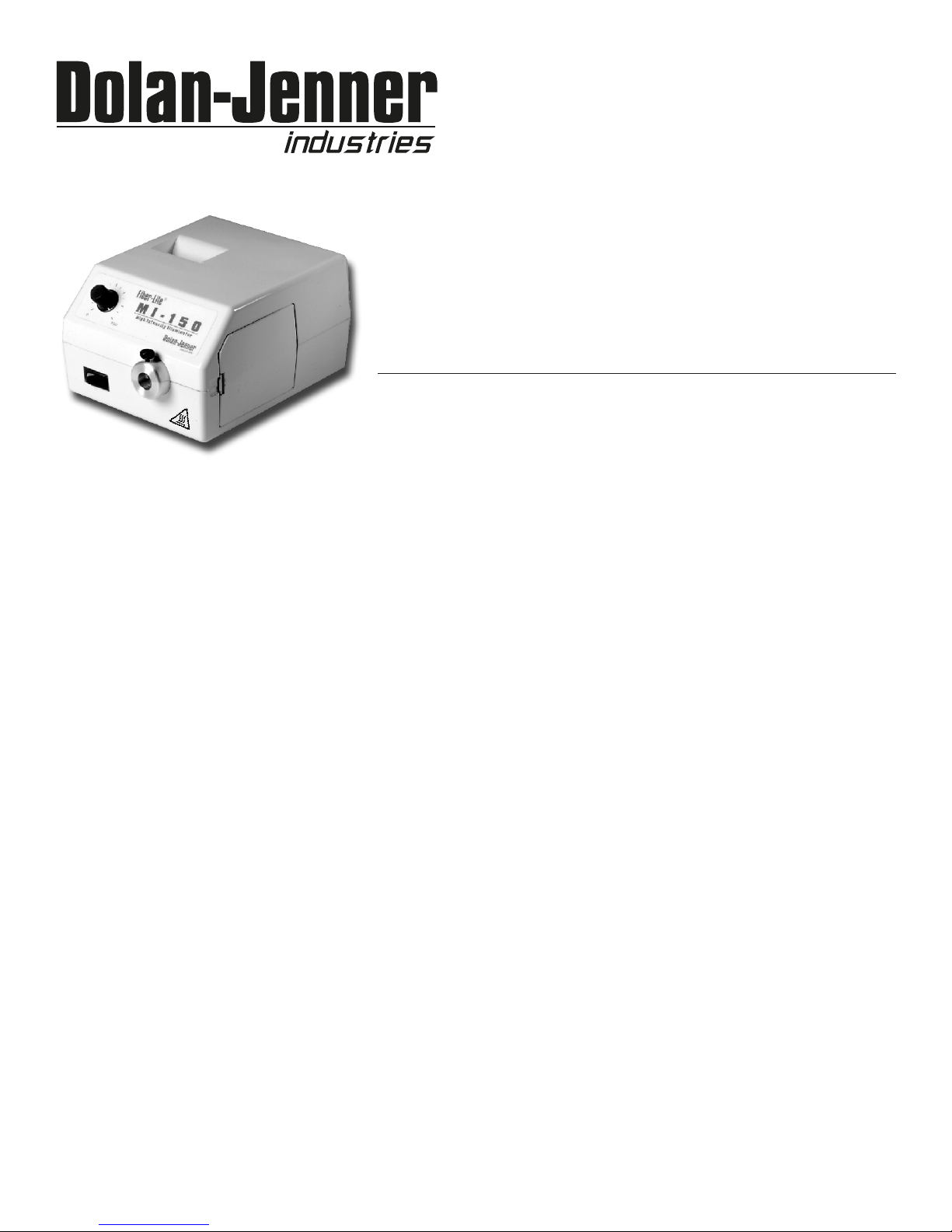
MI-150 ILLUMINATOR
A Product of Dolan Jenner Industries
Introduction
The Fiber-Lite MI-150 is a 150 Watt quartz halogen fiber optic illuminator designed for general microscopy
use. When used with specialty fiber optic cables the MI-150 illuminator can also be used in a variety of
laboratory illumination applications.
Initial Setup
Remove the MI-150 Illuminator from the carton and retain the manual and any additional documents.
Remove the fiber optic cable from the carton if the illuminator was purchased as part of a Fiber Optic
system. If the system includes an EEG2823, EEG3922 or BG2820 self supporting gooseneck fiber optic
cable then also remove the LH759 lens(es) from the carton. The EEG2823 and EEG3922 fiber optic
systems include two(2) LH759 lenses while the BG2820 system includes one(1) LH759 lens.
®
Loosen the fiber optic nosepiece thumbscrew.
Insert the fiber optic tip into the illuminator nosepiece. If the fiber optic is either an EEG2823, EEG3922 or
BG2820 self supporting gooseneck style cable then the tip of the cable will have a small groove in the tip.
The groove in the tip will firmly secure the fiber optic cable in the nosepiece and prevent rotation of the
cable. Align the groove in the tip with the nosepiece thumbscrew. Ringlight fiber optic cables do not have a
groove and can be installed without special alignment.
Tighten the thumbscrew by hand to make a secure connection to the fiber optic. Use of pliers or other
tools is not recommended. Use of tools may result in damage to the illuminator or the fiber optic
cable.
Insert the AC power cord into the power entry at the rear of the illuminator. Use only approved power
cord supplied with the illuminator.
Insert the AC power cord into the proper AC mains outlet for the illuminator voltage ordered. If any doubt
exists consult the labels on the rear and underside of the illuminator before connecting the illuminator to AC
power.
Fiber Optic Connection
The MI-150 illuminator uses a B-type fiber optic nosepiece with a 0.590 in. (15mm) ID. B-Type nosepieces will
accept self-supporting goosenecks (EEG2823, EEG3922, BG2820) and ringlight (A3739) fiber optics without
the need for an adapter. Fiber optics smaller than the 0.590 in. (15mm) ID will require the use of B-type
Page 2
Fiber-Lite
®
Operation
All the MI-150 series illuminators are equipped with a front panel manual solid state intensity control.
FAX: 508-682-2500
Press the ON(1)/OFF(0) rocker switch on the front panel to ON(1). The illuminator will light and is ready for service. The
illuminator intensity is controlled by the rotary control located on the front panel of the illuminator. The 0 position (when
control is turned fully counter-clockwise) corresponds to the lowest illuminator intensity. The 100 position (when control is
turned fully clockwise) corresponds to the highest illuminator intensity. NOTE: Continuous operation of the illuminator
at the highest intensity level will yield rated lamp life. Operating the illuminator at reduced intensity can result in
significantly extended lamp life.
Caution: The fiber optic interface (nose piece) runs at a very high temperature. Avoid contact during use and
when inserting or replacing light guide assemblies.
WARNING
Risk of injury from hot surfaces where indicated
WARNING
Risk of electrical shock. Remove power plug before lamp
!
replacement and wait for hot lamp to cool.
Lamp Replacement
1. Turn the illuminator intensity control fully counterclockwise (the 0 position) and run the illuminator with the fan for several
minutes. Wait until the nosepiece is cool to the touch.
2. Press the ON(1)/OFF(0) rocker switch to the OFF(0) position.
3. Remove the AC power cord from the AC power receptacle.
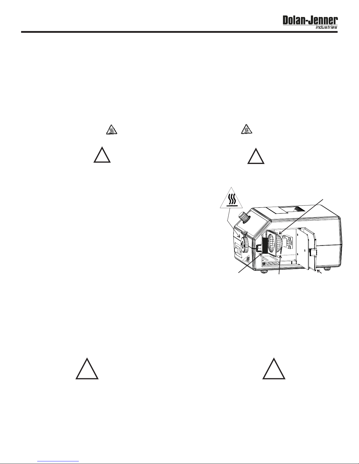
4. Open the lamp access door by depressing the small clip toward the rear of the
illuminator with your thumb or finger. Once the clip disengages from the illuminator
housing the lamp access will spring open several inches. The lamp access door will
open slightly more than 90 to allow easy access to the lamp and lamp socket.
Do not pry open the door with a tool. This may result in damage to the
illuminator housing or the lamp access door.
5. Check the lamp assembly to verify that the lamp and socket are cool before
proceeding. Caution: The lamp runs at very high temperatures and contact
with a hot lamp may result in severe injury.
6. Pull the lamp eject lever to remove the lamp from the socket.
7. Lift and remove the lamp from the lamp socket by grasping the rear of the lamp
adjacent to the lamp
8. Power pins.
9. Remove the lamp from the socket. Discard the old lamp.
10. Insert the replacement lamp into the lamp socket by aligning the lamp power
pins with the slots in the lamp socket. CAUTION: Do not touch the interior of the lamp reflector, the lamp envelope or the
lamp pins with your fingers. Touching the interior of the lamp reflector, the lamp envelope or the lamp pins will result in
significant shortening of the lamp life. Handle the lamp only by the exterior of the reflector or the area adjacent to the
pins.
11. Push the lamp gently into the socket to seat the lamp in the socket and lampholder.
12. Rotate the lamp access door toward the illuminator housing and gently press the lamp access door to cause the door clip to
seat into the housing and secure the door.
13. Reattach AC line cord and the illuminator is ready for service.
o
FILTER
HOLDER
!
LAMP
LEVER
Pull back to eject lamp
SIDE DOOR
Replace the fuse with the correctly rated fuse as listed on the label
on the back of the illuminator. Use of an improper fuse can create a
! !
Filter Option:
MI-150 illuminators ordered with the filter option are shipped with the IR filter and the filter holder installed at the factory. The filter
holder s located behind the illuminator nosepiece, in front of the lamp. (see diagram on page 2)
To use color filters (not included), place color filter into the filter holder behind the IR filter such that the IR filter is located between the
lamp and the color filter.
WARNING: Do not use color filters without an IR filter in place. Filters become HOT with use! Allow sufficient time (10-15 minutes) for
the filters to cool before handling.
WARNING
hazardous situation.
2
Page 3
Fiber-Lite
®
Fuse Replacement
1.
Press the ON(1)/OFF(0) switch to the OFF(0) position.
2.
Remove the AC line cord from the AC power receptacle.
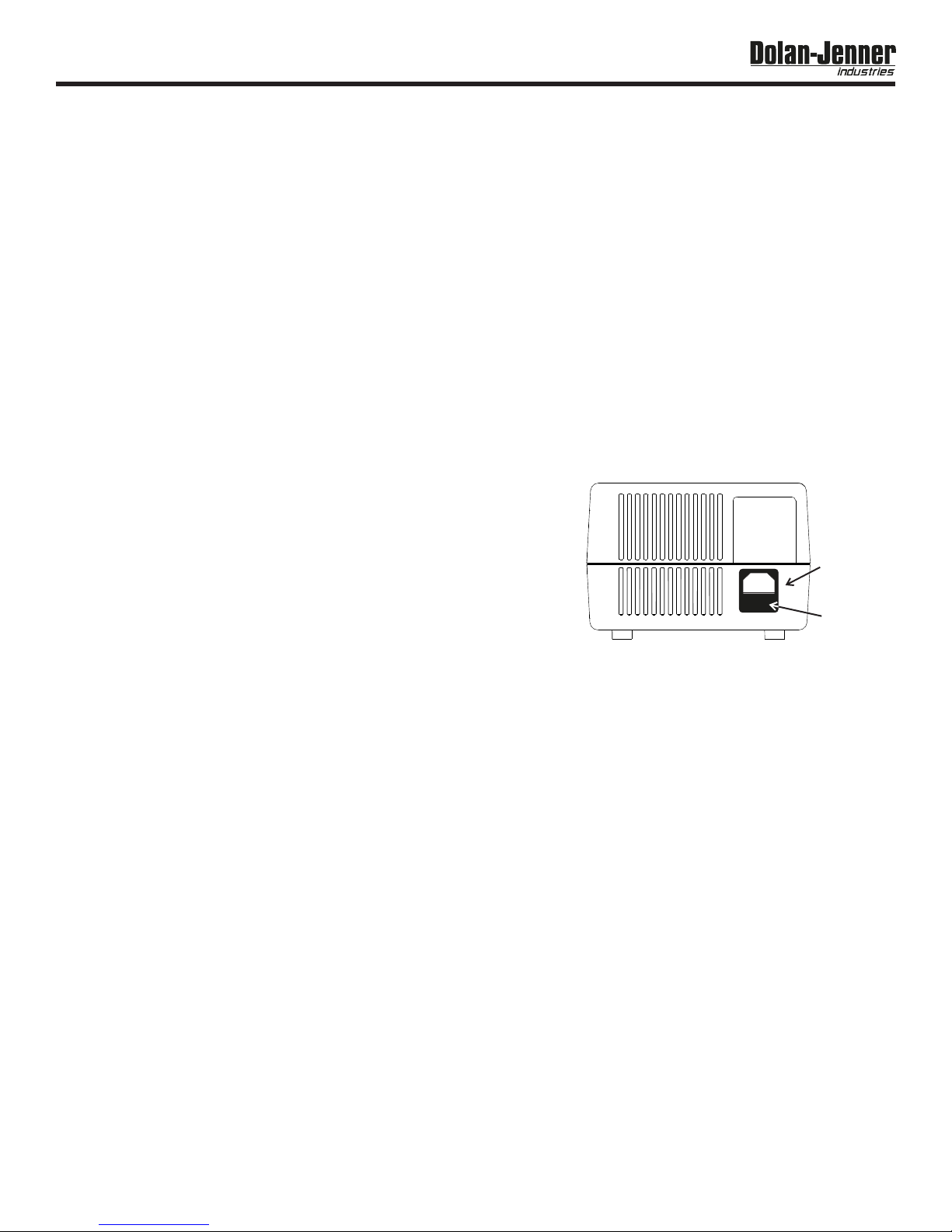
3.
Remove the AC line cord from the power entry module at the rear of the illuminator. The fuse drawer is part
of the power entry module. The drawer is located directly beneath where the AC line cord plugs in.
4.
For 115 VAC illuminators: Pull out the fuse drawer. The AC power fuse is located in the receptacle with
metal clips at both ends of the fuse.
5.
Remove the blown fuse and discard. The second fuse is the spare.
6.
Place the replacement fuse into the metal clips in the fuse drawer. The fuse will work in either orientation.
7.
Push the fuse drawer into the illuminator until it "clicks" into position.
8.
For 230 VAC illuminators: Push down the center latch until it locks in the down position. Remove the fuse
drawer. Two fuses are required.
9.
Remove the blown fuse(s) from the drawer and discard.
10.
Place the replacement fuse(s) into the fuse holder by inserting either end of the fuse into the fuse holder.
11.
Push the fuse drawer until it "clicks" into position.
12.
Attach the AC line cord to power entry module at the rear of the illuminator. The illuminator is now ready for
service.
Replacement Parts
Part No. Description
02-015850-0000 Lamp, EKE, 21V, 150 Watt
02-015852-0000 Lamp, EJV, 21V, 150 Watt
02-015855-0000 Lamp, EJA, 21 V, 150 Watt
02-015320-1300 Fuse, 3A, 5 x 20, 250 V, slow blow (115 VAC)
02-015320-3200 Fuse, 2A, 5 x 20, 250 V, slow blow(230 VAC)
Only above parts are replaceable. Return illuminator to factory for warranty service.
Attempts to replace other parts voids warranty.
Performance Statement
Dolan-Jenner Industries, Inc. (DJI) recognizes that its illuminator products may be used under an almost unlimited
variety of conditions. As such, we are prepared to assist the customer in the selection and application of any of these
products. This includes application engineering, sample testing and other means as determined by DJI.
Where DJI has made specific recommendations for its products, systems, or detection techniques (based on complete
and detailed information furnished by the customer) we will extend every effort to assure that the customer is satisfied with
the performance of our products. Continual development and improvement of DJI products may require changes in
details that do not coincide with descriptions or illustrations shown. All fiber optic cable diameters are nominal.
Three Year Warranty on Light Sources
Dolan-Jenner Industries, Inc. (DJI) warrants its products to be free from defective material and workmanship. Any light
source or parts thereof which are determined by DJI to be defective within 3 years (average product life cycle) from
shipment date will be replaced or repaired at our option. All fiber optics are warranted for one year. This warranty
specifically excludes both incandescent and quartz-halogen lamps, and optical filters.
Any products which, in our opinion, have been subjected to misuse, incorrect wiring, or where installation procedures
are not in accordance with the instruction manual, are excluded from this warranty. Nor does this warranty extend to
products on which repairs or alterations have been made outside the factory, or on which the identification or serial
number has been altered or to accessories not of our manufacture.
Our obligation with respect to products or parts covered by this warranty shall be limited to repair or replacement,
F.O.B., Boxborough, Massachusetts. In no event shall DJI be held liable for consequential or special damages, or for
transportation, installation, adjustment, or other expenses which may arise in connection with such products or parts. This
warranty is in lieu of all other statements or warranties or guarantees, written or implied, by DJI or its authorized
representatives.
Important: Please contact factory for a return authorization number prior to shipping merchandise to factory.
TECHNICAL DATA
POWER
ENTRY
MODULE
FUSE
DRAWER
3
Page 4
Fiber-Lite
®
Technical Data
Lamp 150 W Quartz halogen, 21V (EKE, EJV or EJA) as ordered
Voltages 115 VAC, 200 W, 60 Hz or 230 VAC, 200W, 50 Hz (Set at factory)
Current 1.74 A (115 VAC), 0.87 A (230 VAC)
Lamp Life 200-10,000 Hours depending on intensity
Fuse 115 VAC: 3 Amp, 250V, 3A slow blow, 5 x 20 mm
230 VAC: 2 Amp, 250V, 2A slow blow, 5 x 20 mm
Color Temperature 3100-3400 degrees Kelvin depending on lamp used
Safety Approvals 115 VAC - BV
230 VAC-CE
Dimensions 6 in. L x 8.5 in. W x 5.3 in. H
15.3 cm L x 21.6 cm W x 13.5 cm H
Weight 7.75 lbs. (3.6 kg.)
Max. Housing Temp. 15°C above ambient
Environmental Conditions Use Specifications
Type of Use Indoor at max. altitude of 2,000 M
Ambient Temperature +5°C to +40°C
Relative Humidity 80% maximum up to +31° C (non-condensing)
decreasing linearly to 50% relative humidity @ +40° C
Installation Category II
Pollution Degree 2
NOTICE: If the equipment is used in a manner not specified by the manufacturer, the protection
provided by the equipment may be impaired.
NOTICE: Cleaning of the equipment is not recommended. If the equipment is used in a manner not
specified by the manufacturer, the protection provided by the equipment may be impaired.
Corporate Headquarters and Factory:
Dolan-Jenner Industries, Inc.
159 Swanson Road
Boxborough, MA 01719, USA
WARNING: This is a Class A product. In a domestic environment this product may cause radio
interference in which case the user may be required to take adequate measure.
159 Swanson Road
Boxborough, MA 01719
800.833.4237 • 978.263.1400
Fax 978.264.0292
www.dolan-jenner.com
sales@dolan-jenner.com
Visit our website: www.dolan-jenner.com
05-5300100000 Rev H
4
Page 5
MANUEL DE FOCNTIONNEMENT
Fiber-Lite
®
TM
ILLUMINATEUR MI-150
Un produit de Dolan-Jenner Industries
INTRODUCTION
Le système d'éclairage halogène à quartz et fibres optiques Fiber-Lite MI-150 d'une puissance de 150 watts est destiné
aux applications de microscopie. Lorsqu'il utilise des câbles à fibres optiques spécifiques, le systè
me d'éclairage MI-150 peut être utilisé également dans de nombreuses applications de laboratoire nécessitant une
source lumineuse.
INSTALLATION INITIALE
Déballez le système d'éclairage MI-150 et gardez à portée de main le manuel et les autres documents joints.
Si le système d'éclairage comporte un dispositif à fibres optiques, déballez le câble correspondant (fibres optiques). Si
le système comporte un câble à fibres optiques autoporteur articulé
EEG2823, EEG3922 ou BG2820, déballez également la (les) lentille(s) LH759. Les systèmes à fibres optiques
EEG2823 et EEG3922 incluent deux (2) lentilles LH759, le système BG2820 en inclut une (1).
Dévissez la mollette d'embout du système à fibres optiques.
Insérez l'extrémité des fibres optiques dans l'embout du système d'éclairage. Si le câble autoporteur articulé utilise des
fibres optiques EEG2823, EEG3922 ou BG2820, son embout est muni d'une petite encoche. Celle-ci est destinée à
permettre une fixation efficace du câble dans l'embout et d'éviter toute rotation. Alignez l'encoche avec la molette. Les
câbles à fibres optiques "Ringlight" n'ont pas d'encoche et peuvent être installé
s sans alignement particulier.
Serrez manuellement la molette pour assurer un contact correct des fibres optiques. L'utilisation de pinces ou autres
outils est déconseillée. L'utilisation d'outils est susceptible d'endommager le système d'éclairage ou le câble à
fibres optiques.
Branchez le cordon secteur dans la fiche prévue à l'arrière de l'appareil. N'utilisez que le cordon secteur fourni avec
le système d'éclairage.
Branchez le cordon secteur dans une prise secteur murale offrant la tension correspondant au système d'éclairage dont
vous disposez. En cas de doute, vérifiez les indications des étiquettes à l'arrière et au-dessous du système
d'éclairage avant de le brancher sur le secteur.
Raccordement des fibres optiques
Le système d'é clairage MI-150 utilise un embout à fibres optiques de type B d'un diamètre interne de 15mm. Les
embouts de type B acceptent les systèmes à fibres optiques autoporteurs articulé s (EEG2823, EEG3922, BG2820) et
"ringlight" (A3739) sans adaptateur. Les fibres optiques d'un diamètre interne inférieur à 15 mm né cessitent l'utilisation
d'adaptateurs de type B (SX-5B, SX-6B & SX-7B). Pour de plus amples informations, contactez votre distributeur ou le
fabricant.
®
5
Page 6

Fiber-Lite
®
Utilisation
Tous les systèmes d'é
clairage de la gamme MI-150 sont équipés d'une commande manuelle d'intensité à semi-conducteurs située sur le panneau avant.
Placez l'interrupteur à bascule ON(1)/OFF(0) du panneau de commande en position ON(1). Le système d'éclairage s'allume.
L'intensité lumineuse est commandée par la rotation du bouton situé sur le panneau de commande de l'appareil. La position 0 (lorsque
le bouton est tourné complètement dans le sens inverse des aiguilles d'une montre) correspond à l'intensité lumineuse la plus faible. La
position 100 (lorsque le bouton est tourné complètement dans le sens des aiguilles d'une montre) correspond à l'intensité lumineuse la
plus élevée. NOTE : la mise en fonctionnement continu de l'appareil au niveau d'intensité lumineuse le plus élevé limite la durée de vie
de la lampe. En le faisant fonctionner à intensité réduite, il est possible de prolonger la durée de vie de la lampe de manière
significative.
AVERTISSEMENT
Risque d' électrocution. Retirez la prise d'alimentation
! !
avant de remplacer l'ampoule et attendez que celle-ci
refroidisse
REMPLACEMENT DE L'AMPOULE
Tournez le bouton de contrôle de l'intensité complè tement dans le sens contraire
1.
des aiguilles d'une montre (la position 0) et faites fonctionner l'illuminateur ave le
ventilateur pendant plusieurs minutes. Attendez que l'embouchure refroidisse pour
la toucher.
2.
Appuyez sur l'interrupteur à bascule, ON(1)/OFF(0) sur le panneau principal pour
choisir OFF(0).
3.
Débranchez le fil d'alimentation de la prise secteur.
Ouvrez la trappe d'accès à la lampe en appuyant avec un doigt sur le petit clip situé
4.
à l'arrière du système d'éclairage. Une fois le clip dégagé de l'appareil, la trappe
d'accès s'ouvre d'elle-même de plusieurs centimètres. Elle peut s'ouvrir sur un peu
plus de 90°, ce qui facilite l'accès à la lampe et à la douille. N'ouvrez jamais la
trappe avec un outil. Vous pourriez endommager le boîtier du système d'é
clairage ou la trappe d'accès à la lampe.
5.
Vé rifiez que lampe et la douille sont froides avant de poursuivre les opérations. La
lampe fonctionne à très haute température et un contact éventuel peut conduire à des blessures graves.
Tirez sur le levier pour éjecter la lampe de la douille.
6.
Soulevez et retirez la lampe de la douille en saisissant la partie arrière de la lampe adjacente aux broches d'alimentation.
7.
Retirez la lampe de la douille.
Eliminez la lampe usagée.
8.
9.
Insérez la nouvelle lampe dans la douille en alignant les broches d'alimentation avec les fentes de la douille. ATTENTION : ne
10.
touchez jamais l'intérieur du réflecteur de la lampe, son enveloppe ou les broches avec les doigts. Une telle action est
susceptible de limiter la durée de vie de la lampe de manière significative. Ne manipulez la lampe que par l'extérieur du ré
flecteur ou par la partie adjacente aux broches.
Poussez la lampe doucement dans la douille pour l'installer dans son support.
11.
Faites pivoter la trappe d'accès à la lampe en direction du boîtier du système d'éclairage et appuyez doucement sur cette trappe
12.
pour enclencher le clip dans le boîtier et la refermer.
Attachez le fil d'alimentation. L'illuminateur est prêt à fonctionner.
13.
FILTER
HOLDER
LEVER
Pull back to eject lamp
AVERTISSEMENT
Remplacez le fusible par un fusible de la capacité correcte
comme indiqué sur l’étiquette au dos de l'illuminateur.
L'utilisation d'un fusible incorrecte peut
! !
entraîner une situation dangereuse.
LAMP
SIDE DOOR
OPTION FILTRE
Les systèmes d'éclairage MI-150 commandés avec l'option filtre sont livrés avec le filtre infrarouge et le support intégrés en fabrication.
Le support de filtre est situéderrière la partie proéminente du système d'éclairage, devant la lampe (voir le diagramme de la page 2).
Pour utiliser des filtres de couleur (non inclus), placez le filtre souhaité dans le support derrière le filtre infrarouge, ce dernier se trouvant
placé entre la lampe et le filtre de couleur.
ATTENTION : n'utilisez pas de filtres de couleur sans monter un filtre infrarouge.
Les filtres CHAUFFENT en cours d'utilisation ! Laissez leur le temps de refroidir (10 à 15 minutes) avant de les manipuler.
6
Page 7

Fiber-Lite
®
REMPLACEMENT DU FUSIBLE
1.
Appuyez sur l'interrupteur à bascule, ON(1)/OFF(0) sur le panneau principal pour choisir OFF(0).
2.
Débranchez le fil d'alimentation de la prise secteur.
3.
Retirez le fil d'alimentation du module d'alimentation situé à l'arrière de l'illuminateur. Le tiroir du fusible fait partie du module
d'alimentation. Le tiroir est situé directement en-dessous de l'endroit où se branche le fil d'alimentation.
4.
Pour les illuminateurs 115 V alternatif : Ouvrez le tiroir du fusible en tirant dessus. Le fusible secteur est fixé dans la prise à
l'aide de clips métalliques..
5.
Retirez le(s) fusible(s) sauté(s) et jetez-le(s). Le deuxième fusible est un fusible de rechange.
Placez le fusible de rechange dans le tiroir à fusibles. Le fusible fonctionne dans les deux directions.
6.
7.
Poussez le tiroir à fusibles jusqu'à ce qu'il clique en position. Procédez à l'étape 12.
8.
Pour les illuminateurs 230 V alternatif : Appuyez sur la fermeture centrale jusqu'à ce qu'elle soit verrouillée en position basse.
Retirez le tiroir à fusibles. Vous avez besoin de deux fusibles.
9.
Retirez le(s) fusible(s) sauté(s) et jetez-le(s).
10.
Placez le(s) fusible(s) de remplacement dans leur support en insérant une des extrémités.
11.
Poussez le tiroir à fusibles jusqu'à ce qu'il clique en position.
12.
Attachez le fil d'alimentation. L'illuminateur est prêt à fonctionner.
Part No. Description
02-015850-0000 Ampoule, EKE, 21 V, 150 W
02-015832-0000 Ampoule, EJV, 21 V, 150 W
02-015855-0000 Ampoule, EJA, 21 V, 150 W
02-015320-1300 Fusible, 3A, 5 x 20, 250 V, lent
02-015320-3200 Fusible, 2A, 5 x 20, 250 V, lent
Seules les pièces ci-dessus peuvent être remplacées. Renvoyez l'illuminateur à
l'usine pour toutes réparations sous garantie. Le remplacement de toute autre pièce annule la garantie.
POWER
ENTRY
MODULE
FUSE
DRAWER
DECLARATION DE PERFORMANCES
Dolan-Jenner Industries, Inc. (DJI) reconnaît que ces produits illuminateurs peuvent être utilisés dans un nombre de conditions
pratiquement illimité. En conséquence, nous sommes prêts à aider nos client à sé lectionner un produit et à le faire marcher dans les
conditions choisies. A sa discrétion, DJI peut utiliser ses services d'ingénierie, des tests par échantillon et autres méthodes.
Lorsque DJI faits des recommandations spécifiques concernant ses produits, ses systèmes et ses techniques de détection (sur la base
des informa-tions complètes et détaillé es fournies par le client) nous faisons tout notre possible pour garantie que le client soit satisfait
des performances de nos produits. Le développement et l'amélioration continus des produits de DJI peuvent né cessiter la modifica-tion
de certains détails qui diffèrent alors des descriptions et illustrations de la documentation. Tous les diamètres de gerbes de fibres
optiques sont nominaux.
GARANTIE A Trois SUR LES SOURCES DE LUMIERE
Dolan-Jenner Industries, Inc. (DJI) garantit ses produits contre tous défauts de matériau et de fabrication. Toute source de lumière ou
pièce jugée défectueuse par DJI dans une période de trois ans (duré e de vie moyenne du produit) après la date d'envoi sera
remplacée ou réparée, à notre discrétion. Cette procédure est effective à partir du 1 novembre 1993 et n'est pas ré troactive. Toutes les
fibres optiques sont garanties un an. Cette garantie exclue explicitement les ampoules incandescentes et halogène quartz, ainsi que les
filtres optiques.
Tout produit qui, dans notre seule opinion, a été soumis a une utilisation abusive, un mauvais câblage ont dont les procédures
d'installation ne sont pas en accord avec le manuel d'instruction, sont exclus de cette garantie. Cette garantie ne s'applique pas non
plus au produits qui ont été réparés ou modifiés en dehors de l'usine ou dont le numéro d'identification ou de série a été modifié ou
utilisé avec des accessoires fabriqué s par une tierce partie.
Nos obligations en ce qui concerne les produits et pièces couverts par cette garantie sont limitées à la réparation ou au remplacement
aux portes de l'usine à Boxborough, Massachusetts. DJI ne pourrait en aucun cas ê tre responsable des dommages conséquentiels ou
spéciaux, du transport, de l'installation, du réglage ou autres dépenses reliées à ces produits ou pièces. Cette garantie remplace tout
autre position ou garantie, é crite ou implicite formulée par DJI ou ses représentants.
Important : Veuillez contacter l'usine pour obtenir un numéro d'autorisation de renvoi avant d'expédier
la marchandise vers l'usine.
7
Page 8

Fiber-Lite
®
Caractéristiques techniques
Ampoule 150 W halogè
ne quartz, 21 V (EKE, EJV, ou EJA) en fonction de la commande
Tensions 115 V alt, 200 W, 60 Hz ou 230 V alt, 200 W, 50 Hz (réglé à l'usine)
Courant 1.74 A (115 V alt), 0.87 A (230 V alt)
Durée de vie de l'ampoule 200 à 10 000 heures ; varie selon le réglage de l'intensité
Fusible 115 V alt : 3 A, 250 V, délais, 5 x 20 mm
230 V alt : 2 A, 250 V, délais, 5 x 20 mm
Couleur de la température 3100 à 3400°K selon l'ampoule utilisée
Niveau de bruit environ 21 dB (A)
Certification de sécurité 115 VAC - BV
230VAC-CE
Dimensions 6 in. L x 8.5 in. W x 5.3 in. H (pouces)
15.3 cm L x 21.6 cm W x 13.5 cm H
Poids 7.75 livres (3.6 kg.)
Température max. du boîtier 15° C au dessus de la température ambiante.
Conditions d'utilisation et environnement de fonctionnement
Type d'utilisation Intérieure et à un altitude inférieure à 2000 m
Gamme de températures 5° C à 40° C
Humidité relative maximum de 80% à 31° C, diminuant linéairement jusqu'à 50% à 31° C
Catégorie d'installation II
Degré de pollution 2
AVERTISSEMENT : Si ce matériel est utilisé contrairement aux instructions du fabricant, la garantie risque d'être annulée !
AVIS : Le nettoyage de l'équipement n'est pas recommandé. Si l'équipement est utilisé d'une manière qui n'est pas spécifiée
par le fabricant, la protection fournie par cet équipement peut être affectée.
Siège social et usine :
Dolan-Jenner Industries, Inc.
159 Swanson Road
Boxborough, MA 01719, USA
Telephone: 800.833.4237 or 978-263-1400
Fax: 978-264-0292
Attention: ceci est un produit de classe A. Ina enviornment domestique, ce produit peut provoquer des
interférences radio, auquel cas l'utilisateur peut être amené à prendre des mesures adéquates.
159 Swanson Road
Boxborough, MA 01719
800.833.4237 • 978.263.1400
Fax 978.264.0292
www.dolan-jenner.com
sales@dolan-jenner.com
05-5300100000 Rev H
8
Page 9

BEDIENUNGS-ANLEITUNG
Fiber-Lite
®
TM
MI-150 ILLUMINATOREN
Ein Produkt von Dolan-Jenner Industries
IEINFüHRUNG
Die Fiber-Lite® MI-150 ist ein 150-Watt Quarzhalogen-LWL-Leuchtkörper für allgemeine Mikroskopie. In Verbindung mit
speziell angepaßten Lichtleiterkabeln läßt sich der Leuchtkörper MI-150 aber auch für eine Vielfalt anderer
Beleuchtungszwecke im Labor einsetzen.
INBETRIEBNAHME
Den Leuchtkörper MI-150 einschließlich der Gebrauchsanleitung und sonstiger Beiblätter aus dem Karton nehmen.
Wurde der Leuchtkö
rper im Rahmen eines faseroptischen Gesamtsystems geliefert, auch das Lichtleiterkabel auspacken. Umschließt das
System einen Lichtwellenleiter vom Typ EEG2823, EEG3922 oder BG2820 mit freitragender Anschlußschleife, enthä
lt der Karton ein ebenfalls zu entnehmendes Objektiv LH759. Bei den Lichtleitersystemen EEG2823 und EEG3922
besteht dieses aus zwei (2) Linsen LH759, bei der Vorrichtung BG2820 aus einer (1) Linse LH759.
Die Rändelschraube im Leuchtkörperanschlußstutzen lockern.
Das Ende des Lichtleiterkabels in den Leuchtkörperanschlußstutzen einsetzen. Bei LWL-Kabeln vom Typ EEG2823,
EEG3922 oder BG2820 mit freitragender Anschlußschleife weist das Kabelende eine kleine Nut auf. Diese Nut dient
zum Arretieren des LWL-Kabels im Anschlußstutzen und verhindert jegliche radiale Drehung des Kabels, indem sie mit
der Rändelklemmschraube am Stutzen ausgerichtet wird. Rundlichtkabel sind nicht mit einer Nut versehen und
bedürfen zum Anschluss keiner besonderen Ausrichtung.
Zum Herstellen einer schlüssigen Verbindung des Lichtwellenleiters die Rändelschraube von Hand festziehen. Die
Verwendung einer Zange oder eines sonstigen Werkzeugs ist nicht zu empfehlen, da dies den Leuchtkörper
oder das Lichtleiterkabel beschädigen könnte.
Das Netzkabel am Stromeingang auf der Rückseite des Leuchtkörpers anschließen. Es ist ausschließlich das dafür
vorgesehene, dem Leuchtkörper beiliegende Netzkabel zu verwenden.
Nun das Netzkabel an eine Netzsteckdose mit der richtigen, für den Leuchtkörper vorgesehenen Spannung
anschließen. Im Zweifelsfall sind die Typenschilder an der rückwärtigen und unteren Seite des Leuchtkörpers zu
prüfen, bevor die Einheit an die Netzstromversorgung angeschlossen wird.
Anschließen des Lichtwellenleiters
Der Leuchtkörper MI-150 verfügt über einen Faseroptik-LWL-Anschlußstutzen der Klasse B mit einem Innendurchmesser
von 15 mm (0,590 Inch). Stutzen der Klasse B gestatten die Anbringung von freitragenden Anschluß schleifen (Lichtleiter
vom Typ EEG2823, EEG3922, BG2820) und Rundlichtkabeln (A3739) ohne Zwischenadapter. Lichtleiter mit einem
Durchmesser von weniger als 15 mm (0,590 Inch) erfordern einen Adapter für Stutzen der Klasse B (SX-5B, SX-6B bzw.
SX-7B). Näheres hierzu können Sie von Ihrem zuständigen Händler oder direkt vom Werk erfahren.
9
Page 10

Fiber-Lite
®
Betrieb
Alle Leuchtkörper der Baureihe MI-150 sind mit einem steuertafelmontierten, manuell bedienten, elektronischen
Lichtstärkeregler ausgestattet.
Den EIN(1)-/AUS(0)(ON/OFF)-Kippschalter an der Steuertafel auf ON(1) stellen. Der Leuchtkörper leuchtet und ist
einsatzbereit. Die Lichtstärkeregelung erfolgt mittels des Drehknopfes an der Steuertafel. In der 0-Stellung (bei Drehung
des Knopfes bis zum Anschlag gegen den Uhrzeigersinn) ist die Lichtstärke am geringsten. In der 100-Stellung (bei voller
Drehung des Knopfes im Uhrzeigersinn) ist die Lichtstärke am höchsten. HINWEIS: Bei Dauerbetrieb mit maximaler
Lichtstärke entspricht die Lebensdauer der Lampe dem angegebenen Nennwert. Bei geringerer Stä
rkeeinstellung ergibt sich eine erheblich längere Lebensdauer.
WARNUNG
Berührungsgefahr: elektrischer Schlag. Vor dem Auswechseln der
! !
Lampe stets den Netzstecker ziechen und warten, bis
lampe abgekühlt hat .
AUSWECHSELN DER LAMPE
1.
Folgen Sie den Schritten 1-4 für das Auswechseln des Lampenmoduls.
Überprüfen Sie die Lampenvorrichtung, um sicherzustellen, daß sich Lampe und
2.
Fassung abgekühlt haben, bevor Sie weitermachen.
3.
Ziehen Sie die Lampe aus dem Lampenhalter vollständig heraus, indem Sie den
rückwärtigen Teil der Lampe bei der Lampenfassung anfassen.
4.
Zum Öffnen der Zugangstür zur Lampe mit dem Daumen oder Finger die
kleine Lasche in Richtung der Leuchtkörperrückseite nach unten drücken, bis
die Lasche aus dem Gehäuse ausrastet und die Lampenzugangstür mehrere
Zentimeter aufspringt. Die Tür öffnet sich etwas über 90° und gestattet damit
mühelosen Zugriff auf die Lampe und den Lampensockel. Nicht die Tür mit
einem Werkzeug aufstemmen, da dies das Leuchtkörpergehäuse oder die
Lampenzugangstür beschädigen könnte.
Vor jedem weiteren Schritt sicherstellen, daß sich die Lampe und der Sockel
5.
abgekühlt haben. Die Lampe erzeugt sehr hohe Betriebstemperaturen und
das Berühren der heißen Lampe kann zu schwerer Brandverletzung führen.
Zum Entfernen der Lampe aus dem Sockel am Lampenauswurfhebel ziehen.
6.
Zum Abheben der Lampe vom Sockel die Lampe hinten in Nähe der Kontaktstifte fassen.
7.
Die Lampe vom Sockel entfernen.
8.
Die alte Lampe entsorgen.
9.
Zum Einsetzen der Ersatzlampe die Kontaktstifte mit den Steckbuchsen im Lampensockel ausrichten. VORSICHT:
10.
Nicht die Innenseite des Lampenreflektors, den Lampenkolben oder die Kontaktstifte mit den Fingern berühren, da
jegliche solche Berührung die Lebensdauer der Lampe erheblich verkürzt. Die Lampe ist nur an der
Reflektoraußenseite oder im Bereich neben den Kontaktstiften anzufassen.
Die Lampe vorsichtig in den Sockel bzw. in die Lampenfassung einschieben.
11.
Die Lampenzugangstür auf das Leuchtkörpergehäuse zu drehen und sanft andrücken, bis die Lasche einrastet und
damit die Tür schließt.
12.
Das Netzkabel wieder an die Netzsteckdose anschließen.
13.
FILTER
HOLDER
LEVER
Pull back to eject lamp
LAMP
SIDE DOOR
WARNUNG
Ersetzen Sie die alte Sicherung nur durch eine Sicherung, deren Bemessung
den Angaben auf dem Etikett auf der Rü ckwand des Illuminators entspricht.
Verwendung einer falschen Sicherung kann gefährliche Folgen haben.
! !
FILTER-ZUSATZOPTION
Mit dem Filterzusatz bestellte MI-150 Lichtquellen werden mit werkseitig eingebautem Infrarotfilter einschließlich Fassung geliefert. Die
Filterfassung befindet sich hinter dem Objektivrevolver vor der Lampe (vgl. Zeichnung auf Seite 2).
Zur Verwendung (nicht mitgelieferter) Farbfilter werden diese in die Fassung hinter dem IR-Filter so montiert, daß der IR-Filter
zwischen Lampe und Farbfilter zu liegen kommt.
WARNUNG:
Farbfilter sind grundsätzlich nur in Verbindung mit einem IR-Filter zu verwenden.
Die Filter werden bei Lampenbetrieb HEISS(!) und sind erst nach angemessener Abkühldauer (10-15 Minuten) anzufassen.
10
Page 11

Fiber-Lite
®
AUSWECHSELN DER SICHERUNGEN
1.
Stellen Sie den EIN(1)/AUS(0)-Kippschalter auf AUS(0).
2.
Ziehen Sie das Netzkabel aus der Steckdose.
Ziehen Sie das Netzkabel aus dem Netzteil an der Rückseite des Illuminators. Der Sicherungshalter befindet sich im Netzteil. Es
3.
liegt direkt unterhalb der Anschluß-buchse für das Netzkabel.
Für Illuminatoren mit 115 Volt Wechselstrom-Betrieb: Ziehen Sie den Sicherungshalter heraus. Die Netzstromsicherung
4.
befindet sich im Sicherungskasten und wird an beiden Enden von Metallklammern gehalten.Mit Schritt 12 fortfahren.
5.
Entfernen Sie die durchgebrannte(n) Sicherung(en) aus dem Sicherungsfach und werfen Sie sie weg.
6.
Setzen Sie die Ersatzsicherung in den Sicherungshalter ein. Die Orientierung der Sicherung spielt keine Rolle.
7.
Drücken Sie auf den Sicherungshalter, bis dieser "einschnappt".
Für Illuminatoren mit 230 Volt Wechselstrom-Betrieb: Drücken Sie die mittlere Klappe nach unten, bis sie unten einrastet.
8.
Ziehen Sie den Sicherungshalter heraus. Es werden zwei Sicherungen benötigt.
9.
Entfernen Sie die durchgebrannte(n) Sicherung(en) aus dem Sicherungsfach und werfen Sie sie weg.
10.
Setzen Sie die Ersatzsicher-ung(en) in den Sicherungshalter ein. Die Orientierung der Sicherung spielt keine Rolle.
11.
Drücken Sie auf den Sicherungshalter, bis dieser "einschnappt".
12.
Schließen Sie das Netzkabel an das Netzteil am rückwärtigen Teil des Illuminators an. Der Illuminator ist jetzt betriebsbereit
Beschreibung
02-015850-0000 Lampe, EKE, 21V, 150 Watt
02-015832-0000Lampe, EJV, 21V, 150 Watt
02-015855-0000 Lampe, EJA, 21V, 150 Watt
02-015320-1300 Sicherung, 3A, 5 x 20, 250V, träge (115 VAC)
02-015320-3200Sicherung, 2A, 5 x 20, 250V, träge (230 VAC)
Nur die oben angegebenen Teile können ersetzt werden. Für Garantieansprüche muß der Illuminator an das Werk zurü
ckgeschickt werden. Falls andere Teile ersetzt werden, erlöschen jegliche Garantieansprüche.
POWER
ENTRY
MODULE
FUSE
DRAWER
LEISTUNGEN
Dolan-Jenner Industries, Inc. (DJI), ist sich bewußt, daß seine Illuminatorprodukte unter mannigfaltigen Bedingungen Verwendung
finden können. Es ist deshalb unser Bestreben, unseren Kunden bei der Auswahl und der Anwendung unserer Produkte behilflich zu
sein. Zu diesen Anwendungen zählen technischer Entwurf, Probenauswertung sowie andere von DJI als geeignet befundene
Maßnahmen.
Obwohl DJI spezifische Empfehlungen für seine Produkte, Systeme oder Meßverfahren (basierend auf vollständiger und detaillierter
Informationen unserer Kunden) herausgegeben hat, sind wir stets darum bemüht, sicherzustellen, daß unsere Kunden mit der
Leistungsfähig-keit unserer Produkte zufrieden sind. Ständige Weiterentwicklung und Verbesserungen bei DJI's Produkten können
vereinzelt zu Änderungen führen, wobei dann Produkte nichtmehr genau mit den Beschreibungen und Abbildungen ü
bereinstimmen. Alle Durchmesser der Faseroptikbündel sind nominell.
.
Drei Jahre Garantie fur Light
Dolan-Jenner Industries, Inc. (DJI), garantiert, daß seine Produkte keine Material - und Verarbeitungsmängel aufweisen. Jede
Lichtquelle oder Teile davon, von denen DJI bestätigt, daß diese von innerhalb von drei Jahren (mittlere Produktlebensdauer) nach
Auslieferung ausgefallen sind, werden nach unserem Ermessen entweder ersetzt oder repariert. Diese Richtlinien traten am 1.
November 1993 in Kraft und gelten nicht rückwirkend. Die Garantie für die Faseroptik gilt während eines Jahres. Von dieser Garantie
ausdrücklich ausgeschlossen sind Glühlampen und Quartzhalogenlampen sowie optische Filter.
Alle Produkte, die nach unserer Ansicht mißbräuchlich benutzt oder falsch angeschlossen wurden oder wo die Installation nicht gemäß
unseren Anweisungen vorgenommen wurde, sind ebenfalls von der Garantie ausgeschlossen. Außerdem erstreckt sich die Garantie
nicht auf Produkte, an denen Reparaturen oder Änderungen von Dritten vorgenommen wurden, oder an denen die Kenn- oder
Seriennummer geändert wurde oder auf Zubehör von Fremdherstellern.
Bei allen Produkten oder Teilen, die unter diese Garantie fallen, sind wir nur zur Reparatur oder zum Ersatz verpflichtet, F.O.B.,
Boxborough, Massachusetts. Unter keinen Umständen kann DJI für besondere oder Folgeschäden verantwortlich gemacht werden,
oder für Transport, Installation, Justierung oder andere Kosten, die in Verbindung mit solchen Produkten oder Teilen anfallen. Die
Garantie ersetzt alle anderen Erklärungen oder Garantie, oder Gewährleistungsverpflichtungen, die von DJI oder seinen
Bevollmächtigten schriftlich oder stillschweigend abgegeben wurden.
Wichtig: Bitte wenden Sie sich an unsere Firma, um vor der Versendung der Waren an unser Werk eine autorisierte
Rücknahmenummer zu erhalten.
11
Page 12

Fiber-Lite
®
Technische Daten
Lampe 150 W Quartzhalogen, 21 V (EKE, EJV oder EJA) entsprechend der Bestellung
Spannungen 115 V Wechselstrom, 200 W, 60 Hz oder 230 V Wechselstrom, 200 W, 50 Hz (im Werk eingestellt)
Strom 1.74 A (115 V Wechselstrom), 0.87 A (230 V Wechselstrom)
Lebensdauer der Lampe 200 - 10000 Stunden, abhängig von der eingestellten Leuchtstärke
Sicherung 115 V Wechselstrom: 3 A, 250 V, 5x20 mm, verzögert
230 V Wechselstrom: 2 A, 250 V, 5x20 mm, verzögert
Farbtemperatur 3100-3400° K, abhängig von der verwendeten Lampe
Rauschpegel Ungefähr 21 dB (A)
Sicherheitszulassungen 115 VAC - BV
230 VAC-CE
Abmessungen 6 in. L x 8.5 in. W x 5.3 in. H
15.3 cm L x 21.6 cm W x 13.5 cm H (H x B x T)
Gewicht 7.75 lbs. (3.6 kg.)
Höchsttemperatur des Gehäuses 15°C ü ber der Umgebungstemperatur
Umgebungsbedingungen / Einsatzdaten
Einsatztyp Inneneinbau bei maximal 2000 m.ü.M.
Temperaturbereich 5°C bis 40°C
Relative Feuchtigkeit maximal 80% bis 31°C, dann linear abnehmend auf 50% bei 40°C
Installationskategorie II
Schadstoffgrad 2
Warnung: Die Garantie kann ungültig sein, wenn die Geräte nicht laut Fabrikanten-Anweisungen gebraucht werden.
HINWEIS: Ein Reinigen der Vorrichtung ist nicht zu empfehlen. Anleitungswidrige Verwendung kann die Schutzeigenschaften
der Vorrichtung beeinträchtigen.
Firmenhauptsitz und Werk:
Dolan-Jenner Industries, Inc.
159 Swanson Road
Boxborough, MA 01719, USA
Telephone: 800.833.4237 or 978-263-1400
Fax: 978-264-0292
Achtung: Dies ist ein Produkt der Klasse. Ina inländischen enviornment kann dieses Produkt
Funkstörungen verursachen; in diesem Fall muss der Benutzer verlangt werden, angemessene
Maßnahmen zu ergreifen.
159 Swanson Road
Boxborough, MA 01719
800.833.4237 • 978.263.1400
Fax 978.264.0292
www.dolan-jenner.com
sales@dolan-jenner.com
05-5300100000 Rev H
12
Page 13

MANUAL DE OPERACIÓN
Fiber-Lite
®
ILUMINADOR MI-150
Un producto de Dolan-Jenner Industries
INTRODUCCIÓN
Fiber-Lite® MI-150 es un iluminador óptico de cuarzo halógeno de 150 Vatios diseñado para uso general con
microscopios. Cuando se usa con cables especiales de fibra óptica, el iluminador MI-150 también se puede
emplear en otras aplicaciones de iluminación de laboratorio.
INSTALACIÓN INICIAL
Extraiga el MI-150 de la caja y guarde el manual y cualquier documento adicional.
Si el iluminador fue comprado como parte de un sistema de fibra óptica, saque el cable de fibra óptica de la
caja. Si el sistema incluye un cable de fibra óptica de conexión en S con soporte propio, modelos
EEG2823, EEG3922 ó BG2820, entonces saque también el (las) lente(s) LH759 del cartón. Los sistemas
de fibra óptica EEG2823 y EEG3922 incluyen dos (2) lentes LH759 mientras que el sistema BG2820
incluye una (1) lente LH759.
Afloje la tuerca del portaobjetivo de fibra óptica.
Inserte la punta del cable de fibra óptica en el iluminador del portaobjetivo. Si el cable de fibra óptica es de
conexión en S con soporte propio, modelos EEG2823, EEG3922 ó BG2820, la punta del cable tendrá una
pequeña ranura. La ranura en la punta asegurará de manera firme el cable de fibra óptica en el
portaobjetivo y evitará que el cable gire. Alinee la ranura en la punta con el tornillo del portaobjetivo. Los
cables de fibra óptica para lá
mparas circulares no tienen una ranura y pueden ser instalados sin alineación especial.
Apriete la tuerca para hacer una conexión segura al cable de fibra óptica. No es recomendable el uso de
alicates o de otras herramientas. El uso de herramientas puede causar daño al iluminador o al cable de
fibra óptica.
Inserte el cordón de corriente alterna (AC) en la entrada de corriente en la parte posterior del iluminador.
Utilice solamente el cordón aprobado que se suministra con el iluminador.
Inserte el cordón en la toma de corriente alterna (AC) apropiada para el voltaje del iluminador pedido. Si
existe cualquier duda, lea las etiquetas en la parte posterior e inferior del iluminador antes de conectar é
ste a la toma de corriente alterna.
TM
Conexión de fibra óptica
El iluminador MI-150 usa un portaobjetivo de fibra óptica del tipo B con un diámetro interno de 0.590 pulgadas
(15 mm). Los portaobjetivos del tipo B aceptará
n los cables de fibra óptica de conexión en S con soporte propio (modelos EEG2823, EEG3922 ó BG2820) y
las lámparas circulares (A3739) sin necesidad de ningún adaptador. Los cables de fibra óptica de diá
metro interno menor de 0.590 pulgadas (15 mm) requerirán el uso de adaptadores del tipo B (modelos SX-5B,
SX-6B y SX-7B). Póngase en contacto con el distribuidor o con el fabricante para información adicional.
13
Page 14

Fiber-Lite
®
REEMPLAZO DEL FUSIBLE
Girar el interruptor de encendido (1)/apagado (0) a la posición de apagado (0).
1.
Remover el cable eléctrico de corriente alterna del receptáculo de corriente alterna.
2.
3.
Remover el cable de corriente alterna del mó dulo de entrada de poder en la parte posterior del iluminador. El compartimiento del
fusible es parte del módulo de entrada de poder. El compartimiento esta localizado directamente debajo del lugar donde se
conecta el cable de corriente alterna.
4.
Para iluminadores de 115 VAC: Jalar hacia afuera el compartimiento del fusible. El fusible de corriente alterna se encuentra en el
receptáculo con sujetadores de metal a ambos extremos del fusible. Vaya al paso.
5.
Remover el fusible quemado que está ubicado mas cerca del iluminador y botarlo en la basura. El segundo fusible es el repuesto.
6.
Colocar el fusible de repuesto en el compartimiento del fusible. El fusible funciona en cualquier orientación.
7.
Empujar el compartimiento hasta que se escuche un "clic" indicando que ya está en posición.
8.
Para iluminadores de 230 VAC: Empujar hacia abajo el pestillo central, hasta que se fije en la posición baja. Remover el
compartimiento del fusible. Se requieren dos fusibles.
9.
Remover de el compartimiento el (los) fusible (s) quemados y botarlo(s) en la basura.
10.
Colocar el (los) fusible (s) de repuesto en el soporte de fusibles, insertando ambos lados de el fusible en el soporte de fusibles.
11.
Empujar el compartimiento del fusibles hasta que se escuche un "ruido" indicando que ya está en posición.
12.
Conectar el cable de corriente alterna en el módulo de entrada de energia en la parte trasera del iluminador. De está manera, el
iluminador queda listo para ser.
Descripción
02-015850-0000 Lámpara, EKE, 21V, 150 Watts
02-015832-0000Lámpara, EJV, 21V, 150 Watts
02-015855-0000 Lámpara, EJA, 21 V, 150 Watts
02-015320-1300 Fusible, 3A, 5 x 20, 250 V, de quemado lento
02-015320-3200 Fusible, 2A, 5 x 20, 250 V, de quemado lento
Solo los repuestos incluidos en la lista son reemplazables. Enviar el iluminador
a la fabrica para servicio cubierto por la garantía. Atentos de reemplazar otras
partes anula la garantía.
POWER
ENTRY
MODULE
FUSE
DRAWER
NOTA ACERCA DEL FUNCIONAMIENTO
Dolan-Jenner Industries, Inc. (DJI) reconoce que sus productos "iluminador" pueden ser utilizados casi bajo una variedad ilimitada de
condiciones. Por lo que, estamos preparados para asistir al cliente en la selección y aplicación de estos productos. Ésto incluye
ingeniería de aplicació n, pruebas de muestras y de aquellas otras formas tal como sea determinado por DJI.
Cuando DJI ha hecho recomendaciones específicas para sus productos, sistemas o técnicas de detección (basados en una completa y
detallada informació n proporcionada por el cliente) nosotros pondremos todo nuestro esfuerzo para asegurar la satisfacción del cliente
con el funcionamiento de nuestros productos. El desarrollo y mejora continua de los productos DJI podrá requerir cambios en detalles
que no coincidan con las descripciones o detalles mostrados. Todos los diámetros de haces de fibra óptica son nominales.
8
TRES ANOS DE GARANTIA DE FUENTES DE LUZ
Dolan-Jenner Industries, Inc. (DJI) garantiza que sus productos no presentan defectos de mano de obra y material. Cualquier fuente
de luz o repuestos incluidos y determinados por DJI que presenten defectuoso dentro de tres anos (ciclo promedio de vida de los
productos) después de haber sido enviados al cliente, serán reemplazados o reparados, a opción nuestra. Esta política es vigente a
partir del 1 de Noviembre de 1993 y no es retroactiva. Todas las fibras ó pticas son garantizadas por un año. Esta garantí
a excluye específicamente las lámparas incandescentes y las de halógeno de cuarzo y los filtros ópticos.
Cualquier producto que en nuestra opinión halla sido objeto de uso incorrecto, alambrado incorrecto o que la instalació n no se halla
realizado de acuerdo al manual de instrucciones, está excluido de esta garantía. Tampoco se extiende esta garantía, a productos que
hallan sido alterados o reparados fuera de la fabrica, o aquellos en los que el nú mero de serie o de identificación halla sido alterado o
accesorios no producidos por nosotros.
Nuestra obligación con relación a los productos o repuestos cubiertos por est garantía estará limitada a reparaciones o reemplazo,
F.O.B. Boxborough, Massachusetts. Bajo ninguna circunstancia DJI será responsable por dañ
os consiguientes o especiales, o por transporte, instalación, ajuste u otros gastos que puedan surgir en conexión con tales productos o
repuestos. Esta garantía es en reemplazo de cualquier otra declaración o garantí as o fianzas, escritas o implicadas por DJI o sus
representantes autorizados.
Importante: Por favor contactar la fabrica para obtener un número de autorización de retorno antes de enviar la
mercadería a la fabrica.
15
Page 15

Fiber-Lite
®
Operación
Todos los iluminadores de la serie MI-150 están equipados con un controlador de intensidad de estado sólido
manual en el panel frontal.
Oprima el interruptor de encendido/apagado (ON/OFF) en el panel frontal a la posición de encendido (ON)(1).
El iluminador se encenderá y estará listo para trabajar. La intensidad del iluminador se controla con el
controlador giratorio que se encuentra en el panel frontal del iluminador. La posición "0" (cuando el controlador
es girado completamente en el sentido opuesto al de las agujas del reloj) corresponde a la intensidad de luz
más baja del iluminador. La posición "100" (cuando el controlador es girado completamente en el sentido de
las agujas del reloj) corresponde a la intensidad más alta del iluminador. NOTA: Si se opera de manera
continua el iluminador al nivel de intensidad más alto, la duración de la lámpara será la de su vida nominal. Si
se opera el iluminador a una intensidad reducida, la vida de la lámpara tendrá una extensión mayor.
PRECAUCIÓN
Riesgo de choque eléctrico. Remover el enchufe eléctrico reemplazar
! !
la lampara y esperar que la lámpara caliente se enfrie.
REEMPLAZO DE LA LÁMPARA
1.
Seguir los pasos 1 - 4 de el Reemplazo del módulo de la lámpara.
2.
Revisar el montaje de la lámpara para verificar que la lámpara y el enchufe
estén fríos, antes de comenzar.
3.
Levantar y remover la lámpara de su soporte, sujetando la parte posterior
de la lámpara contigua al enchufe de la lámpara.
4.
Abra la puerta de acceso de la lámpara oprimiendo con el dedo la pequeña
lengüeta en la parte posterior del iluminador. Una vez que la lengüeta se
suelta de la cubierta del iluminador, el resorte de acceso a la lámpara se
abrirá unas cuantas pulgadas. La puerta de acceso a la lámpara se abrirá
algo más de 90° para permitir el fácil acceso a la lámpara y al zócalo de la
misma. No abra la puerta de acceso haciendo palanca con una
herramienta. Esto puede provocar daños en la cubierta del iluminador y en
la puerta de acceso.
Revise el ensamblado de la lámpara para verificar que la lámpara y el
5.
zócalo están fríos antes de proseguir. La lámpara opera a temperaturas
muy altas y el contacto con la lámpara caliente puede resultar en una lesión seria.
6.
Tire de la palanca de eyección de la lámpara para sacar esta del zócalo.
7.
Levante y saque la lámpara del zócalo agarrando la parte trasera de la lámpara adyacente a las espigas de corriente.
8.
Saque la lámpara del zócalo.
9.
Descarte la lámpara usada.
Inserte la lámpara de reemplazo en el zócalo alineando las espigas de corriente de la lámpara con las ranuras en el
10.
zócalo de la lámpara. PRECAUCIÓN: No toque con sus dedos el interior del reflector de la lámpara, la cubierta de la
lámpara o las espigas de la lámpara. El tocar con los dedos la parte interior del reflector, la cubierta de la lámpara o
las espigas de la lámpara, provocará un acortamiento significativo de la vida de la lámpara. Maneje la lámpara
solamente por la parte exterior del reflector o por el área adyacente a las espigas.
11.
Empuje suavemente la lámpara dentro del zócalo para asentarla en el zócalo y en el sujetador de la lámpara.
12.
Gire la puerta de acceso de la lámpara hacia la cubierta del iluminador y suavemente oprima la puerta de acceso
para que la lengüeta de la puerta se asiente en la cubierta y asegure la puerta.
Inserte el cordón de corriente alterna (AC) en el receptáculo de corriente alterna (AC).
13.
FILTER
HOLDER
LEVER
Pull back to eject lamp
LAMP
SIDE DOOR
OPCIÓN PARA EL FILTRO
Los iluminadores MI-150 ordenados con la opción para el filtro se envían con el filtro IR y el sostenedor del filtro IR instalado de
fábrica. El sostenedor del filtro está ubicado detrás del pico del iluminador, al frente de la lámpara. (Vea el diagrama en la página 2.)
Para usar filtros de colores (no están incluidos), coloque el filtro de color en el sostenedor detrás del filtro IR de forma que el filtro IR
quede entre la lámpara y el filtro de color.
ADVERTENCIA: No utilice filtros de colores sin tener instalado un filtro IR. Los filtros se CALIENTAN con el uso. Permita suficiente
tiempo (de 10 a 15 minutos) para que los filtros se enfríen antes de manejarlos.
14
Page 16

Fiber-Lite
®
Datos técnicos
Fiber-Lite Series MI-150
Lámpara Halógeno de cuarzo de 150 W, 21V (EKE, EJV o EJA) de acuerdo a orden
Voltajes 115 VAC, 200 W, 60 Hz or 230 VAC, 200 W, 50 Hz (ajustado en la fabrica)
Corriente 1.74 A (115 VAC), 0.87 A (230 VAC)
Tiempo de vida de la lámpara 200-10,000 horas, dependiendo de la intensidad a la que trabaje
Fusible 115 VAC: 3 Amp, 250 V, retardo de tiempo, 5 x 20 mm
230 VAC: 3 Amp, 250 V, retardo de tiempo, 5 x 20 mm
Temperatura del color 3100-3400° grados Kelvin, dependiendo de la lámpara usada.
Nivel de ruido aproximadamente 21 dB (A)
Aprobaciones de seguridad 115 VAC - BV
230 VAC-CE
Dimensiones 6 in. L x 8.5 in. W x 5.3 in. H Alto x Ancho x Profundidad
15.3 cm L x 21.6 cm W x 13.5 cm H
Peso 7.75 lbs. (3.6 kg.)
Máxima temperatura de la caja 15° C sobre la temperatura ambiente.
Especificaciones de uso para condiciones ambientales
Tipo de uso Interior, a una altitud máxima de 2,000 M
Rango de temperatura 5° C a 40° C
Humedad relativa a 80% máximo hasta 31° C disminuyendo
linealmente hasta 50% de humedad relativa a 40° C
Categoría de instalación II
Grado de contaminación 2
®
AVISO: Si el equipo es utilizado en una forma diferente a la espicificada po el fabricante, puede dañarse la protección
proveída por el equipo!
No es recomendable la limpieza del equipo. En caso de que no se sigan las indicaciones de uso del fabricante, la protección
provista por el equipo será menor.
Fabrica y oficina central de la Corporación:
Dolan-Jenner Industries, Inc.
159 Swanson Road
Boxborough, MA 01719, USA
Telephone: 800.833.4237 or 978-263-1400
Fax: 978-264-02923-1400
Advertencia: este es un producto de clase A. Ina enviornment doméstico, este producto puede causar
interferencias de radio, en cuyo caso puede ser necesario que el usuario tome la medida adecuada.
16
159 Swanson Road
Boxborough, MA 01719
800.833.4237 • 978.263.1400
Fax 978.264.0292
www.dolan-jenner.com
sales@dolan-jenner.com
05-5300100000 Rev H
 Loading...