

Page 1
OperationManual
Fiber-Lite
®
A241/A242DCREGULATED
FIBEROPTICILLUMINATORS
AProductofDolanJennerIndustries
INTRODUCTION
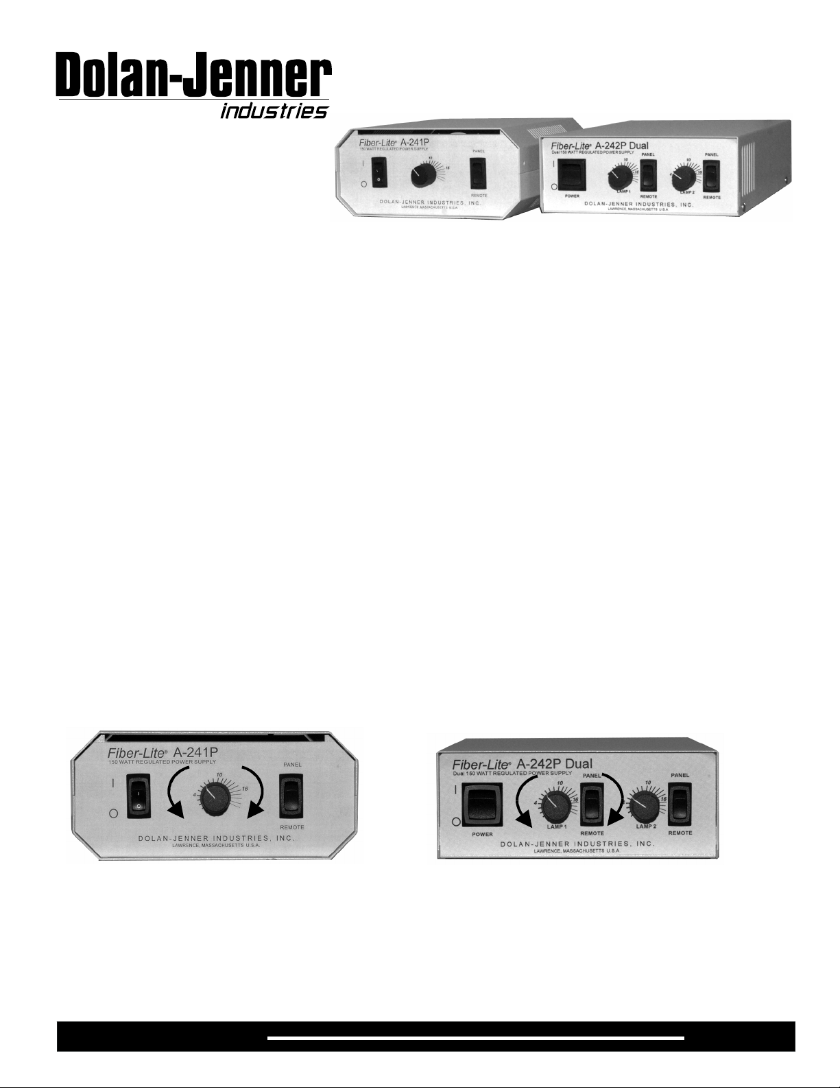
TheA-241andA-242seriesisafamilyof150Watt,highlyregulated,DCpoweredquartzhalogenfiberopticilluminators.The
A-241andA-242illuminatorsaredesignedforawiderangeofapplicationsfromlaboratoryandindustrialillumination
applicationstoprecisemachinevisionillumination.TheA-241illuminatorconsistsofanA-241Ppowersupplyunit andone(1)
A-241Llampmodule.TheA-242illuminatorconsistsofanA-242Ppowersupplyunitandtwo(2)A-241Llampmodules.
OPERATION
Insertthepowercordintothepowerentrymoduleattherearofthepowersupply.Next,insertthepowercordintoa3wire
groundedACpowerreceptacle.(Theilluminatorpower
supplycomessetfromthefactoryaseither115VACor230VAC.ContacttheFactoryifyoudesiredoperationatanalternate
voltage.)
Connectthelamppowercable(s)totheA-241Llampmodule(s)(A-242hastwo(2)lamppowercables).
PresstheON(1)/OFF(0)rockerswitchonthefrontpaneltoON(1).Theilluminatorwilllightandisreadyforservice.
MANUALINTENSITYCONTROL
Useonlyapprovedpowercordsuppliedwiththeilluminator.
AlltheA-241P/A-242Pseriesilluminatorsareequippedwithafrontpanel,rotarysolidstateintensitycontrol.The0position
(whencontrolisturnedfullycounter-clockwise)correspondstothelowestilluminatorintensity.The100position(whencontrol
isturnedfullyclockwise)correspondstothehighestilluminatorintensity.
NOTE:
illuminatoratreducedintensitycanresultinsignificantlyextendedlamplife.
Continuousoperationoftheilluminatoratthehighestintensitylevelwillyieldratedlamplife.Operatingthe
Decrease Increase
Decrease
Increase
REMOTEINTERFACE
ToenabletheremoteinterfacemovethePANEL/REMOTEswitchonthefrontpaneltotheREMOTEposition.Whentheswitch
isintheREMOTEposition,thefrontpanelintensitycontrolisnotactive.IftheRemoteIntensityControlSignalisnotconnected,
theilluminatorwillrunatthemaximumintensitysettinguntiltheRemoteIntensityControlSignalisconnected.
Page1A241P/A242P
Page 2
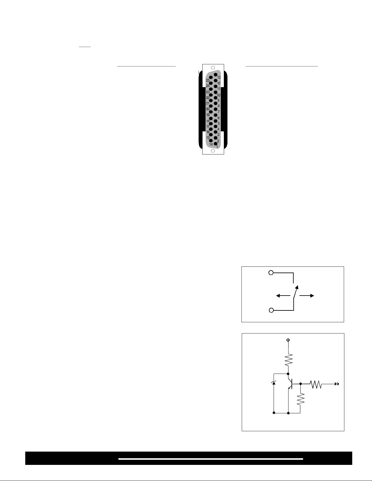
DIGITALMODELREMOTEINTENSITYCONTROL
TheDigitalRemoteIntensityControlusesan8bit,latching,parallelinputDigitaltoAnalogconverter.TheDigitalRemote
IntensityControlisCentronicsparallelcompatible.Refertothepinoutbelow.
NOT
DigitalRemoteControl-PinAssignments
PROGRAMMINGTHE
REMOTEDIGITAL
INTERFACE
PINDESCRIPTIONPINDESCRIPTION
1+5v10mAmax.10InputEnable(CE)
2DB0(LSB)11-22CommonGround
3DB123LampFail
Establishthedigitalcontrol
codeontopinsDB0(LSB)to
DB7(MSB).
PulltheInputEnablepin10
Lowtoloadthecodeintothe
remoteinterface.
PulltheInputEnablepin10
Hightolatchthecodeintothe
remoteinterface.Thedigital
codewillremainloadeduntila
newcodeisprovidedandtheInputEnablesignalistoggled.
4DB224RemoteOn/Off
5DB325Open
6DB4
7DB5
8DB6
9DB7(MSB)
IntensityLevel/DigitalCode
IntensityBinaryCodeHexCode
21.0volts(fullpower)11111111FFh
10.5volts(approx.1/2power)1000000080h
0volts(min.power)0000000000h
Aone(1)bitchangeinthedigitalcodeisequivalentapproximatelyto82millivolts.Thedigitalcodetolampvoltage islinearover
the0to255rangeofinputs.
RESPONSETIME
TheRemoteControlmodulewillrespondtothechangeindigitalinputwithinseveralmillisecondsoftheInputEnable falling
edge.However,duetothethermalinertiaofthelamp,theilluminationlevelofthelampmaytakeseveralhundredmillisecondsto
severalsecondstoresponddependingonthemagnitudeoftheintensitychange.Theresponsetimeisalsoafunctionofthe
individuallampcharacteristicsandmaychangefromlamptolamp.
Pin1
REMOTEON/OFFFUNCTION
TheRemoteOn/OfffunctionwilloperatewiththePanel/Remoteswitchinboththe
PanelandRemotepositions.Connecta+5vsignaltopin14toinhibitpowertothe
lamp.Thefanwillstilloperate.
Removethe+5vsignalfrompin24(pin14onAnalogmodels)toenablepowerto
thelamp.The+5vonpin1canbeusedforthisfunction.Useamanualswitch.relay
orFETswitchtoconnectandremovethe5vsignalonpin24(pin14onAnalog
models).
LAMPFAILSIGNAL
AsignalindicatingthatthelamphasfailedisavailableonPin23(pin17onAnalog
models).Thissignalisopencollector(seeFigureIV).Theusermustsupplythe
necessarycircuitrytoconnectthelampoutsignaltoasignalingdevice.The
maximumcurrentthroughthecircuitis10mA.WhenthesignalatPin
Analogmodels)
TheLampFailsignalwilldetectifcurrenthasstoppedflowingtothelampwhilethe
intensitycontrolsignalisnotat0volts,theilluminatorOn-OffswitchisintheOn
positionandtheRemoteOn-OffsignalisintheOncondition.TheLampFailsignal
willalsoindicateifthelampisnotproperlyseatedafteralampchangeorifthe
lamppowerconnectorisnotproperlyconnectedafteralampchangeorifthelamp
socketwasreplaced.
islogicHigh(5v)thelamphasfailed.
23(pin17on
+5v
Lamp
PowerOff
Pin24
Pin14onAnalogmodels
PIN23(17Analog)
47 W
LampFailCkt.
Lamp
PowerOn
10K
Page2A241P/A242P
Page 3

ANALOGMODELREMOTEINTENSITYCONTROL
(ModelsA241PAandA242PA)
TheRemoteIntensityControlislocatedonPin3oftheRemoteInterface.
WhenthePANEL/REMOTEswitchisintheREMOTEpositiontheintensity
iscontrolledbythesignalappliedtoPin3.Theinputsignalmustbelimited
toa0to+5voltDCsignal.Anegativevoltageoravoltageinexcessof5
voltswillcausethelamptorunatmaximumintensitypotentiallyshortening
lamplife.TheA-241P/A-242PRemoteIntensitycontrolishighlylinear.At0
voltsthelampvoltageis0volts.At+5voltsthelampvoltageisthemaximum
voltageforthelampspecifiedatthetimetheorderwasplaced.A2.5volt
input signalwillcausethelamptorunat50%oflampvoltage.RefertoTable
Aforintermediatevalues.
Pin1canbeusedtosupplypowertoaremotepotentiometer.
ConnectthepotentiometerasshowninFigureA.The500ohm
seriesresistorpreventsshortingthepowersupplyonPin1ifthe
potentiometershouldfailasashortcircuit.Inallcasesthe
minimumresistancebetweenPin1andcommonground(Pins2
and15)mustbeatleast500ohmstopreventdamagetothePin1
powersupply.
AnalogRemoteControl-PinAssignments
Pin#-Signal
1+5VDCat10mAmax.
30-5V(+)input
2,150-5V(-)input(commonreturn)
14RemoteOn/OffOpen
16Chassisground(shield)
17LampFail
4-13Open
18-25Open
Theusermayalsouseafixedvoltagedividertocontrolthe
Pin1
illuminatoratanon-varyingintensitylevel.RefertoFigureBand
theresistancevaluesinTable1forsampleresistorvaluesandthe
correspondinglampintensitylevels.Inallcases,theminimum
Pin3
totalresistancevalueconnectedbetweenPin1andcommon
ground(Pins2and15)mustbe500ohms(RA+RB500ohms.)>
WARNING
Replacethefusewiththecorrectly
ratedfuseaslistedonthelabel
onthebackoftheilluminator.Useof
animproperfusecancreate
ahazardoussituation.
FUSEREPLACEMENT
!
PresstheON(1)/OFF(0)switchtotheOFF(0)position.
!
RemovetheAClinecordfromtheACpowerreceptacle.
!
RemovetheAClinecordfromthepowerentrymoduleattherearoftheilluminator.Thefusedrawerispartofthepower
Pin2
RA()RB()VoltageVDC%@FullIntensity
ΩΩ
20K5.0100%
20K2.2K4.590%
20K5K4.080%
20K8.6K3.570%
20K13K3.060%
20K20K2.550%
13K20K2.040%
8.6K20K1.530%
(Pin3)
R
A
R
B
entrymodule.ThedrawerislocateddirectlybeneathwheretheAClinecordplugsin.
!
Pulloutthefusedrawer.Removetheblownfuse.Thesecondfuseisthespare.
!
Placethereplacementfuseintothefusedrawer.Thefusewillworkineitherorientation.
!
Pushthefusedraweruntilit"clicks"intoposition.
!
AttachtheAClinecordtopowerentrymoduleattherearoftheilluminator.Theilluminatorisnowreadyforservice
.
CLEANING
Ifnecessarywipeexteriorsurfacesonlywithasoftcloth.Donotusefluidstocleantheexterioroftheilluminator. Underno
circumstancesallowfluidsofanykindtoentertheilluminatorpowersupplyorlampmodule(s).
REPLACEMENTPARTS
PartNo.ModelDescription
686009-02787A241PFuse,3.15A,5x20,250V,slowblow
686009-02786A242PFuse,6.3A,5x20,250V,slowblow
PERFORMANCESTATEMENT
Dolan-JennerIndustries,Inc.(DJI) recognizesthatitsilluminatorproductsmaybeusedunderanalmostunlimitedvarietyofconditions.
Assuch,wearepreparedtoassistthecustomerintheselectionandapplicationofanyoftheseproducts.Thisincludesapplicationengineering,
sampletestingandothermeansasdeterminedbyDJI.
WhereDJIhasmadespecificrecommendationsforitsproducts,systems,ordetectiontechniques(basedoncompleteanddetailed
informationfurnishedbythecustomer)wewillextendeveryefforttoassurethatthecustomerissatisfiedwiththeperformanceofourproducts.
ContinualdevelopmentandimprovementofDJIproductsmayrequirechangesindetailsthatdonotcoincidewithdescriptionsorillustrations
shown.Allfiberopticbundlediametersarenominal.
Page3A241P/A242P
Page 4

LIFETIMEWARRANTYONLIGHTSOURCES
Dolan-JennerIndustries,Inc.(DJI) warrantsitsproductstobefreefromdefectivematerialandworkmanship.Anylightsourceorpartsthereof
whicharedeterminedbyDJItobedefectivewithinthree years(averageproductlifecycle)fromshipmentdatewillbereplacedorrepairedatouroption.
ThispolicyiseffectiveNov.1,1993andisnotretroactive.Allfiberopticsarewarrantedforoneyear.Thiswarrantyspecificallyexcludesboth
incandescentandquartz-halogenlamps,andopticalfilters.
Anyproductswhich,inouropinion,havebeensubjectedtomisuse,incorrectwiring,orwhereinstallationproceduresarenotinaccordancewiththe
instructionmanual,areexcludedfromthiswarranty.Nordoesthiswarrantyextendtoproductsonwhichrepairsoralterationshavebeenmadeoutside
thefactory,oronwhichtheidentificationorserialnumberhasbeenalteredortoaccessoriesnotofourmanufacture.
Ourobligationwithrespecttoproductsorpartscoveredbythiswarrantyshallbelimitedtorepairorreplacement,F.O.B.,Boxborough,Massachusetts.
InnoeventshallDJIbeheldliableforconsequentialorspecialdamages,orfortransportation,installation,adjustment,orotherexpenseswhichmay
ariseinconnectionwithsuchproductsorparts.Thiswarrantyisinlieuofallotherstatementsorwarrantiesorguarantees,writtenorimplied,byDJIor
itsauthorizedrepresentatives.
Important:Pleasecontactfactoryforareturnauthorizationnumberpriortoshippingmerchandisetofactory.
TECHNICALDATA
SupplyVoltage:115VAC,50/60Hzor230VAC,50/60HzFactorySet.
PowerConsumptionA-241P-200Watts
A-242P-400Watts
FuseA-241P-Single3.15Amp,250V,timedelay,5x20mm
A-242P-Dual6.3Amp,250V,timedelay,5x20mm
NoiseLevelApproximately32dB(A)
SafetyApprovalsUL,C-UL,CE
DimensionsA-240PPowerSupply8.0in.Wx12.0in.Dx3.25in.H
A-240PDualPowerSupply8.0in.Wx16.5in.Dx3.25in.H
WeightA-240PPowerSupply6.25lbs.
A-240PDualPowerSupply8lbs.
Max.HousingTemp.A-241P<10°Caboveambient
A-242P<15°Caboveambient
EnvironmentalConditionsUseSpecifications
TypeofUseIndooratmax.altitudeof2,000M
InstallationCategoryII
TemperatureRange5°Cto40°C
RelativeHumidity80%max.upto31°Cdecreasinglinearlyto50%relativehumidity@40°C
PollutionDegree2
NOTICE:iftheequipmentisusedinamannernotspecifiedbythemanufacturer,theprotection
providedbytheequipmentmaybeimpaired.
EuropeanSalesOffice:CorporateHeadquartersandFactory:
Dolan-JennerEuropeB.V.Dolan-JennerIndustries,Inc.
P.O.Box345
5400AHUden,Holland
Tel:4132-6930Telephone:978-263-1400800-833-4237
Fax:4132-60938Fax:978-264-0292
ELECTROMAGNETIC
COMPATIBILITY
(INACCORDANCEWITHTHEEMCDIRECTIVES89/336/EEC)
Dolan-JennerIndustries,Inc.declaresthatthe
Fiber-LiteA241/A242seriesoffiberoptic
illuminatorscomplieswiththefollowingEMC
standards:
EN61010-1
EN55011,ClassB,Level1
EN50082-1
IEC801-2
IEC801-3
IEC801-4
(Testreportsavailableforreviewatthe
manufacturer.)
®
159 Swanson Road, Boxborough, MA 01719
www.dolan-jenner.com
e-mailto:sales@dolan-jenner.com
AuthorizedSignature
Date
Dolan-JennerIndustries,Inc.
159 Swanson road
Boxborough, MA 01719USA
05-530013-0000RevA
Page4A241P/A242P
 Loading...