

Page 1
MANUAL FL180/170
®
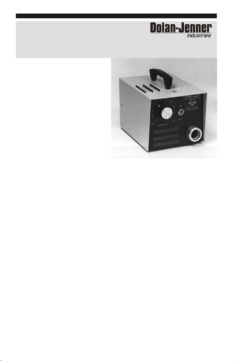
Fiber-Lite
HIGH INTENSITY FIBER OPTIC ILLUMINATORS
INSTRUCTION
MANUAL
for Models 180 & 170-D
Illuminators
Your purchase of the Dolan-Jenner
Fiber-Optic Illumination System will
provide you with many years of service
in a large variety of applications which
require high intensity, yet cool
illumination. Please read the following
instructions to ensure that maximum
performance is obtained from your system.
Model 180 and 170-D Illuminators are readily interchangeable within the systems. The
exceptions are with System 181, 181A and 181B which require the Model 180
Illuminator for the support of the self-supporting fiber optic light pipes EEG 2823, EEG
3922 and BG 2820. In addition the Model 180 has the lowest noise and vibration
characteristics that can be incorporated into any unit, which makes it especially suitable
for high magnification stereo-microscope usage.
Fiber-Lite Illuminators achieve maximum reliability and lamp life due to certain design
considerations incorporating air flow parameters that result in long lamp life and cool
housing temperatures as well as component reliability.
ADAPTERS (SX TYPE)
The Adapters fit into the Illuminator nosepiece with the flat area facing up. The idler
hole on the flat area is off center, and the shortest dimension faces the illuminator when
inserted.
The SX 5, 6, & 7 adapters are made with an idler which provides quick disconnect
features that require only a few turns of the thumbscrew on the Illuminator nosepiece to
attach or disengage the fiber optic light pipe.
SYSTEM 181 ASSEMBLY INSTRUCTIONS
Due to the self-supporting features of the fiber optic light pipes (BG 2820, EEG 2823,
EEG 3922) it is necessary to remove the thumbscrew on the Illuminator and replace it
with a 7/64 socket head cap screw provided. The SX-11 adapter is then inserted as above
followed by the fiber optic pipe with the flat surface facing up. . Then insert the fiber
optic pipe with the flat surface facing up. Use an Allen Wrench to sufficiently secure the
fiber optic so that there is no rotation.
Page 2
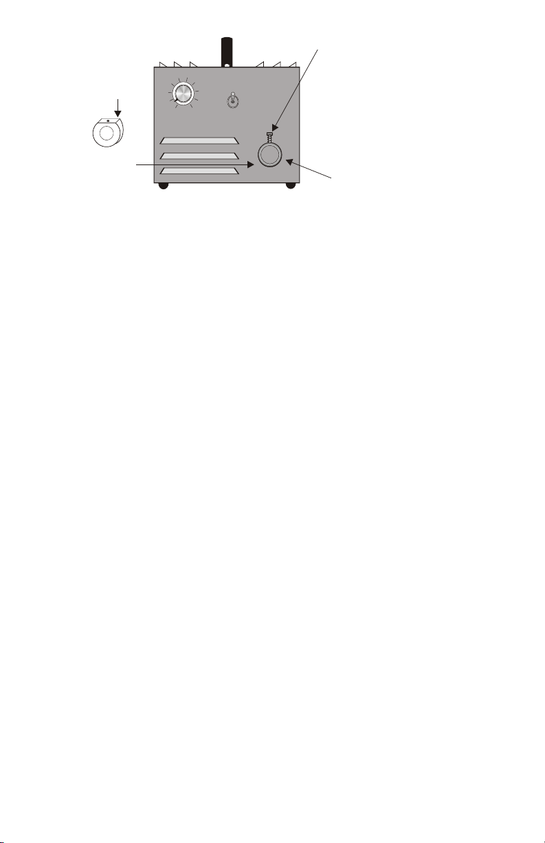
THUMBSCREW
FLAT with
IDLER HOLE
INSERT ADAPTER
3
4
2
5 6
1
INTENSITY
7
ON
8
9
10
OFF
(For system 181,
181A and 181B see
System 181 Assembly
instructions.)
NOSEPIECE
FIBER OPTIC LIGHT PIPE INSERTION
Insert the Fiber Optic Light Pipe into the adapter and tighten the thumbscrew to secure
the fiber optic in the Illuminator.
MOUNTING STANDS
For some applications a mounting stand is required to secure the fiber optic gooseneck
in an operating position. The EEG 3736 fiber optic has a hole in the transition to accept
the securing knob on the MS-7 Mounting stand. The MS-8 Mounting stand requires that a
portion of the gooseneck be clamped directly.
LENSES
The LH755 lens is threaded on the fiber optic light pipe after the locking nut. The
LH759 lens is quickly attached or removed from the fiber optic with a turn of the
thumbscrew. Both lenses are capable of focusing the light to provide higher levels of
illumination and obtaining focused light spot diameters of .16" (.4cm) to 2.87" (7.3cm).
ANNULAR ILLUMINATION SYSTEMS
Annular Illumination Systems provide 360 degrees oblique crosslighting for detail
delineation and a crisp visual or photographic image at working distances of 1.5" (3.8
cm) to 9.5" (24.1 cm). As is the case with most non-self-supporting fiber optics and
especially with this system, a capability for electronic flash photography is acquired by
simply approximating the fiber optic to the flash source. This system has numerous
adapters for attaching the fiber optic to various models and makes of microscopes. These
adapters necessarily vary and a separate instruction sheet is provided for each.
A WORD ABOUT FIBER OPTIC LIGHT PIPES
The light pipe contains a bundle of individual glass fibers about the size of a human
hair. Each fiber consists of a central optical glass core and is cladded with a different
refractive index which allows for the transmission of light through total internal
reflection, a phenomenon in which light rays are reflected at the core/clad interface and
travel to the distant end of the fiber by a zigzag path of successive reflections. To assure
maximum light input/output each fiber bundle has an optical polish at each termination.
These bundles are then constructed in a protective sheathing to limit a bend radius
which, if exceeded, could cause the fibers to fracture. The fiber optic light pipe should be
treated as a laboratory instrument and considerate, common sense usage will assure an
unlimited lifetime. Avoid sudden forceful pressures on bends and excessive
configurations that strain the flexibility of the fiber optic.
Periodically the ends of the fiber optic and lenses should be cleaned with a lens cleaner
and lens paper.
Page 3

BK
G
LINE
BK
G
LINE
XFMR
W
LAMP
FAN MOTOR
R
W
SCHEMATIC
180
BK
BK BK
FAN MOTOR
LAMP
XFMR
W
BK
W
R
W
SCHEMATIC
170 - D
BK BK
CHANGING THE ILLUMINATOR LAMP
Should the need arise to replace the EKE type lamp the following procedure should be
used:
1. Unplug the illuminator from the wall socket.
2. Wait until the illuminator nosepiece is cool to touch.
3. Raise the cover of the illuminator.
4. Pull up on the EKE lamp to remove it from the lamp holder.
5. Remove the lamp from the socket.
6. Replace with a new EKE lamp.
CAUTION: Do not touch either the inner quartz lamp envelope or the lamp pins with
your fingers. This will result in a significant shortening of lamp life. Handle the EKE
lamp only by the dichroic reflector when attaching the lamp socket.
7. Reinsert the lamp holder.
8. Close cover.
9. Insert plug in wall socket and, if necessary, check the alignment of the lamp.
10. The lamp holder is precision aligned at the factory on the angle for optimum lamp
input into the fiber optic. Occasionally there are dimensional variations of replacement
lamps that may result in a reduction of illumination. The reduction is apparent when
illuminating a piece of white paper at a distance of three inches with an unlensed fiber
optic. Should there be visible a central area of less intensity than the periphery, the lamp
should be aligned. This condition is due to the physical positioning of the quartz
envelope within the reflector and can be eliminated by the following:
W
ALIGNMENT:
1. Illuminate a piece of paper with the distal end of the fiber optic about 3" away. Do not
use a lens. Check for a darker central area.
2. Place the illuminator on its side and loosen the two lamp holder adjustment screws on
the base. With the screws loose, rotate the lamp holder until the darker central area
changes to a brighter intensity than the periphery.
3. Secure the screws at the best position obtainable.
Page 4

PERFORMANCE STATEMENT
Dolan-Jenner Industries, Inc. (DJI) recognizes that its illuminator products may be used
under an almost unlimited variety of conditions. As such, we are prepared to assist the
customer in the selection and application of any of these products. This includes application
engineering, sample testing and other means as determined by DJI.
Where DJI has made specific recommendation for its products, systems or detection
techniques (based on complete and detailed information furnished by the customer), we will
extend every effort to assure that the customer is satisfied with the performance of our
products. Continual development and improvement of DJI products may require changes in
details that do not coincide with descriptions or illustrations shown. All fiber optic bundle
diameters are nominal.
TWO YEAR WARRANTY ON LIGHT SOURCES
Dolan-Jenner Industries, Inc. (DJI) warrants its products to be free from defective material
and workmanship. Any light source or parts thereof which are determined by DJI to be
defective within two years from date of shipment will be replaced or repaired at our option.
This policy is effective August 1, 2005 and is not retroactive. All fiber optics are warranted for
one year. This warranty specifically excludes both incandescent and quartz-halogen lamps,
sockets, fuses and optical filters.
Any products which, in our opinion, have been subjected to misuse, neglect, incorrect
wiring, or where installation procedures are not in accordance with the instruction manual, are
excluded from the warranty. Nor does this warranty extend to products on which repair or
alterations have been made outside the factory, or on which the identification or serial number
has been altered, or to accessories not of our manufacture.
Our obligation with respect to products or parts covered by this warranty shall be limited to
repair or replacement, F.O.B., Boxborough, Massachusetts. In no event shall DJI be held liable
for consequential or special damages, or for transportation, installation, adjustment, or other
expenses which may arise in connection with such products or parts. This warranty is in lieu
of all other statements or warranties or guarantees, written or implied, by DJI or its authorized
representatives.
Important: All merchandise returned to the factory for repair must be accompanied by a completed return form available
on http://www.setra.com/tra/repairs/pdf. Please contact factory for a return authorization number prior to shipping
merchandise to factory
REPLACEMENT PARTS
MODEL 170D MODEL 180
PART NO. DESCRIPTION PART NO. DESCRIPTION
02-015002-0000 Transformer 02-015004-0000 Transformer
02-015904-0000 Lamp Holder-QEZ-10M 02-015904-0000 Lamp Holder-QEZ-10M
02-023301-0001 Lamp Socket-QCZ-34 02-023301-0001 Lamp Socket-QCZ-34
02-013800-5001 Rheostat-50 ohms, 25W 02-015302-1250 Fuse, 2.5A 250V 3AG Slo-Blo
02-015850-0000 Lamp EKE, 150W, 21V 02-013801-5001 Rheostat-50ohms, 50W
02-001054-0000 Fan 02-015850-0000 Lamp EKE, 150W, 21V
02-018201-0002 Switch 02-001003-0000 Fan
02-001500-0000 Fan Guard 02-018201-0001 Switch
® Dolan-Jenner Industries All Right Reserved Printed in U.S.A. Rev. D 05-000007-0000
Dolan-Jenner Industries, Inc. • 159 Swanson Road. • Boxborough, MA 01719
For 115V, 50/60 Cycle Version
02-001502-0000 Fan Guard
Components for 220V, 50/60Hz
02-015004-0001 Transformer
02-015302-1125 Fuse, 1.25A 250V 3AG Slo-Blo
02-013801-1502 Rheostat
02-001007-0000 Fan
(978) 263-1400 • FAX: (978) 264-0292
E-Mail sales@dolan-jenner.com
 Loading...