

DogWatch Scoot Operating Instructions Manual
Hidden Fence Systems
®
Operating Instructions for
DogWatch Scoot
TM
Important Safeguards
■
Please read the DogWatch
Owner’s Guide before starting
installation and training.
■
Keep the receiver collar and
transmitter out of reach of
children.
■
Never adjust the transmitter
while your pet is wearing the
receiver collar.
■
Unplug the transmitter when
the system is left unused for
extended periods.
■
This product is for indoor use
only.
BE DEFECTIVE. IN NO EVENT WILL DOGWATCH INC. BE LIABLE
FOR ANY SPECIAL, INDIRECT OR CONSEQUENTIAL DAMAGES
ARISING OUT OF THE PURCHASE OR USE OF THE PRODUCT. IN
NO EVENT SHALL DOGWATCH INC.’S LIABILITY EXCEED THE
PURCHASE PRICE OF THE PRODUCT.
DogWatch, DogWatch logos, Performance Series, and SafeLink are registered
trademarks of DogWatch Inc. FastReact, AutoMemory, Pet-Friendly, PowerPak, Scoot,
GroundsKeeper, HouseKeeper, It’s All About Your Dog, Surrounding Pets With Freedom
Since 1990 and Simply The Best... No Getting Around It are trademarks of DogWatch Inc.
The Consumers Digest logo and Best Buy Seal are registered trademarks of
Consumers Digest and used under license.
DogWatch products are protected under U.S. Patent numbers: 5,353,744; 5,465,687;
6,079,367; 6,360,698; 6,467,435; 6,575,120; 6,825,768 and D,491,481.
This device complies with part 15 of the FCC Rules. Operation is subject to the
following two conditions: (1) This device may not cause harmful interference, and
(2) this device must accept any interference received, including interference that may
cause undesired operation.
DogWatch products are lead-free and compliant with the
Reduction of Hazardous Substances (RoHS) initiative.
©2007 DogWatch Inc. All rights reserved. 295051 Rev. A 01-07
®
10 Michigan Drive■Natick,MA 01760■800-793-3436■www.dogwatch.com
Hidden Fence Systems
®
You can activate your warranty by registering online at
www.dogwatch.com, then click “Customer Service”.
Features
Scoot
T
M
is designed for small indoor
applications and allows you to
protect almost any area of your
house. Applications include
protecting your furniture, drapes,
carpets, window sills, countertops,
stairways, beds, cribs, etc.
Power Simply plug the power
supply into the transmitter jack.
Indicator Light A green light lets
you know that both the transmitter
and boundary wire are functioning
properly. A red light lets you know
that your boundary wire is not
connected properly or has a break.
Range The transmitter emits a
coded radio signal through up to 25 feet of boundary wire. You can
adjust the distance the signal radiates off the boundary wire by
using the left switch on the back of Scoot. When the switch is set to
the “HIGH” position, the range will be approximately two feet off the
wire. When the switch is set to the “LOW” position, the range will be
approximately one foot off the wire. Always test the signal field
before allowing your pet near the avoidance area. Never adjust the
transmitter while your pet is wearing the receiver collar.
Terminal Connections Strip and connect one end of the boundary
wire to one of the terminal connections. This is the beginning of
your boundary wire system. Once you have completed your
boundary, strip and connect the other end of your boundary wire to
the other terminal. The boundary wire must make a complete loop.
If the green power light turns to red it means that your boundary
wire is not connected properly or that there is a break in the wire.
Adjusting the Collar
Collar tightness is critical. All contact points must touch your dog’s
skin in order to receive a correction. A loose collar will also allow the
contact posts to rub back and forth on the skin, possibly causing
irritation. Use care as over-tightening the contact posts could cause
damage to the receiver.
We recommend that the receiver collar be removed each day to
allow your dog’s skin to gradually condition itself to the contact
posts and avoid potential skin irritation and possible infections.
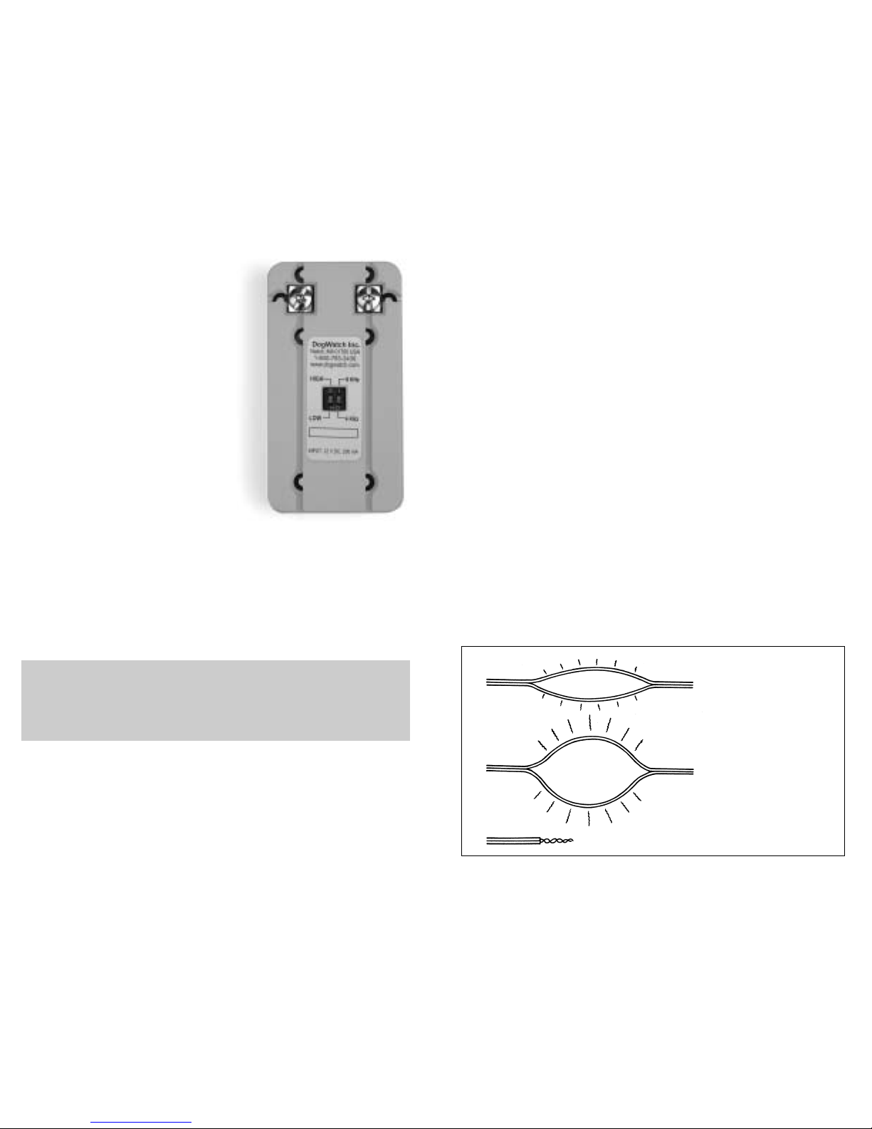
Installation
To create a signal field using the boundary wire, you need to
separate the two strips of wire. The range of the signal will depend
upon the distance the two strips of wire are from one another. When
the two strips are next to one another, there is no signal field. As the
two strips are separated, the signal field will increase (see Figure 1).
The boundary wire must form a continuous loop for there to be a
signal field. To accomplish this, you must splice the final ends of the
boundary wire together.
The boundary wire carries a harmless radio signal. You do not need
to worry about an electrical shock when separating and splicing the
boundary wire. The power indicator light will be “red” if you have not
closed the boundary loop or if you have a broken boundary wire.
32
Note: On the back of Scoot there are two small switches. The right
switch sets your transmitter to the correct broadcast frequency.
Your dealer will set this right switch for your system.
Do NOT change these settings. They are for DEALER USE ONLY.
Smaller Signal Field
Larger Signal Field
Splice The Ends Together
Figure 1
 Loading...