

Dogu KKS 093 - 093, KKS 062 - 046, KKS 062 - 062, KKS 093 - 062, KKS 124 - 093 Installation, Operation And Maintenance Instructions
...Page 1

AIR HANDLING UNIT INSTALLATION,
OPERATION AND MAINTENANCE INSTRUCTIONS
is a registered trademark of Dogu Iklimlendirme A.S
Page 2
Venues Breathe with Dogu HVAC Systems!
Dogu HVAC Systems which had started to produce ventilation and air-conditioning equipments in İzmir in 1999,
produce two main segments as air outlet equipments and air handling units in accordance with European
norms (DIN,EN). Dogu puts the devices on the market with ‘’Four Season’’ brand.
Dogu HVAC Systems which is in business within 45.000m² open area with 2 factory, has 120 different types of
products. It brings new products to the sector producing Make-up Kitchen Hoods, Laminar Flow Ceiling, One
Piece Square Ceiling Diffuser.
Our R&D journey started in 2004 with the first project of producing Make-up Kitchen Hood is followed by
producing dozens of other new products that were designed by special software like Ansys Fluent® and
Solidworks® today.
Page 3

is a registered trademark of Dogu Iklimlendirme A.S
- Protect your unit against damage, shock and distortions.
- Do not attemp to install and run the unit before reading the instructions in this booklet
- Your unit’ s serial number is
- Your unit’ s type is
MODELS
KKS 062 - 046
KKS 062 - 062
KKS 093 - 062
KKS 124 - 062
KKS 093 - 093
KKS 124 - 093
KKS 155 - 093
KKS 124 - 124
KKS 155 - 124
KKS 186 - 124
KKS 155 - 155
KKS 186 - 155
KKS 217 - 155
KKS 186 - 186
KKS 217 - 186
KKS 248 - 186
KKS 217 - 217
KKS 248 - 217
KKS 279 - 217
KKS 310 - 217
KKS 248 - 248
KKS 279 - 248
KKS 310 - 248
KKS 341 - 248
KKS 403 - 248
KKS 465 - 248
KKS 527 - 248
KKS 589 - 248
Air Handling Unit Installation, Operation And Maintenance Instructions
www.doguhvac.com
1
Page 4

2
www.doguhvac.com
Air Handling Unit Installation, Operation And Maintenance Instructions
CONTENTS Pages
- INTRODUCTION ........................................................................................................................................... 3
- ABOUT AIR HANDLING UNITS .................................................................................................................. 3
- TRANSPORTATION AND STORAGE ......................................................................................................... 4
- INSTALLATION ............................................................................................................................................ 4
4.1 CONNECTION OF SECTIONS .............................................................................................................. 5
- CONNECTIONS ............................................................................................................................................ 6
5.1- DUCTING CONNECTIONS ................................................................................................................... 6
5.2- PIPING CONNECTIONS ....................................................................................................................... 9
5.3- CONDENSATE DRAIN LINES ............................................................................................................ 11
5.4- ELECTRICAL CONNECTIONS .......................................................................................................... 11
6-
7
8
9
SETTING UP OF COMPONENTS .............................................................................................................. 18
6.1- DAMPERS ........................................................................................................................................... 18
6.2- FILTERS .............................................................................................................................................. 18
6.3- COILS .................................................................................................................................................. 18
6.4- HUMIDIFIERS ...................................................................................................................................... 19
6.5- SUPPLY AND RETURN FANS ........................................................................................................... 20
6.6- ELECTRIC HEATER ........................................................................................................................... 20
- SAFETY ...................................................................................................................................................... 20
7.1- USE OF THE UNIT .............................................................................................................................. 21
7.2- OBSERVATION OF WARNING SIGNS .............................................................................................. 21
7.3- STAFF TRAINING ............................................................................................................................... 21
7.4- PREVENT OF COMMON DANGERS AND RİSKS ............................................................................ 22
7.5- RECOMMENDED SAFETY PRACTICES ........................................................................................... 22
7.6- THE HIDDEN DANGER ...................................................................................................................... 23
7.7- START UP ........................................................................................................................................... 24
- MAINTENANCE .......................................................................................................................................... 25
- BELT TENSION AND ALIGNMENT CONTROL ........................................................................................ 29
10
1
2
3
4
5
- CHANGE OF PULLEYS .......................................................................................................................... 31
10.1- MOUNTING OF PULLEYS ................................................................................................................ 31
10.2- REMOVAL OF PULLEYS ................................................................................................................. 31
11- LUBRICATION OF BEARINGS ............................................................................................................... 31
12- TROUBLESHOOTING ............................................................................................................................. 33
12.1- TROUBLESHOOTING CHART ................................
......................................................................... 34
13- OPERATING LIMITS OF FANS............................................................................................................... 37
14- MOTOR TECHNICAL INFORMATION .................................................................................................... 41
APPENDIX-1 STARTER SELECTION TABLE ............................................................................................... 44
15- PRODUCING COMPANY ........................................................................................................................ 45
TABLE ............................................................................................................................................................. 45
16- WARRANTY ............................................................................................................................................. 46
17- DELIVERY REPORT ................................................................................................................................ 47
18- DECLERATION OF CONFORMITY ........................................................................................................ 48
Page 5

Air Handling Unit Installation, Operation And Maintenance Instructions
www.doguhvac.com
3
1- Introduction
This manual is prepared as a guide to good practice in installation, operation and maintenance of air
handling units manufactured by DOGU IKLIMLENDIRME A.S. The manual contains basic information and
recommendations for proper and fail free operation of air handling units. Please read the instructions and
warnings given in this manual and on the air handling unit before starting installation, operation and
maintenance works and keep this manual near the unit, within easy reach of service personnel.
2- About Air Handling Units
WARNING: DOGU IKLIMLENDIRME A.S. air handling unit are only used for heating, ventilating and air
conditioning purposes. Any other use is considered not in conformity with general provisions. The
manufacturer is not responsible for damages resulting; the user will be the only responsible.
Standard units must not be used for handling of flammable gases. Spark-proof versions of rotating parts
(fans, motors etc.) must be selected for this kind of applications, so air handling unit manufacturer should
be informed while ordering the unit.
2.1 Operating Data
2.1.1 Ambient Temperature
Air handling unit components are suitable to be used at ambient temperatures between -20˚C and +40˚C
and altitude of 1000m. Ambient temperature is the temperature of the air either inside or the outside of the
unit. If the unit is to be used at ambient temperature and altitude other than stated above please consult
to DOGU IKLIMLENDIRME A.S.
2.1.2 Power Supply
Standard power supply for air handling unit components such as motors, humidifier pumps, electric
heaters, steam humidifiers etc. is 400V, 3ph, 50 Hz and for lighting 230V, 1ph, 50Hz. However customers
may request other voltages while ordering the unit.
WARNING: Before starting electrical connections and selection of electrical components check if the mains
power supply conforms to the data on the rating plates of electrical components. If there is any difference
do not connect the devices.
2.1.3 Coils
If not otherwise stated on the capacity label, maximum operating temperature and pressure:
For hot and cold water coils: 90˚C, 10 bar
For high temperature hot water coils: 150˚C, 15 bar
For steam coils: 143˚C, 3 bar
Page 6
4
www.doguhvac.com
Air Handling Unit Installation, Operation And Maintenance Instructions
WARNING: Do not operate coils above the maximum temperature and pressure specified on the capacity
label.
2.1.4 Motors And Fans
Rated power, speed and current values of commonly used motors are given on pages 35 - 36 and maximum speed and maximum installed power values of fans are given on pages 33 - 34 for information only.
It is not permitted to operate fans and motors at higher speeds other than design speed, without written
permission of DOGU IKLIMLENDIRME A.S., since operating at higher speeds may overload and damage the
motor and fan.
3- Transportation And Storage
Air handling units are inspected prior to dispatch for good condition and carefully loaded. Special care must
be taken while unloading the units.
Air handling units are generally damaged during transportation and loading / unloading, especially when
being lifted by a crane. Small units can be transported by hand-powered pallet truck or by forklift truck.
4- Installation
During final installation the requirements of EN 60204-1 do apply.
Before manufacturing air handling unit, the client should check the conditions at site to ensure that access
routes are adequate for both size and weight of the unit sections. Air handling unit installation areas should
also be checked. There should be sufficient space around the unit for servicing, maintenance and piping
connections. Further, it must be ensure that the base is high enough from the floor to allow the condensate
drain with necessary water trap.
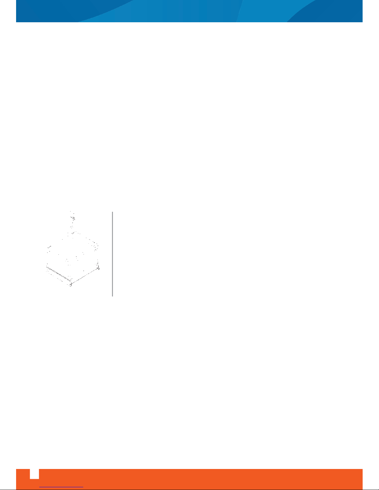
WARNING: Always use the lifting holes on the base frame to lift the unit by a
crane. Never lift the units by coil connections or by any other protrusions. While
hoisting or lowering, proper lifting equipment (slings and spreaders properly
selected on the ground of the size and weight of the section) should be used
not to damage the unit. Ensure that slings do not damage the unit casing and
protrusions such as coil pipe connections, door handles, drain connections etc.
Safety precautions should also be taken not to tilt and not to drop the unit.
Fig. 1: Typical lifting equipment
Page 7
Air Handling Unit Installation, Operation And Maintenance Instructions
www.doguhvac.com
5
WARNING: Air handling units should be installed on a rigid and level surface. Correct alignment of the
sections is essential to maintain a satisfactory airtight enclosure and to avoid distortion to the casing and
components.
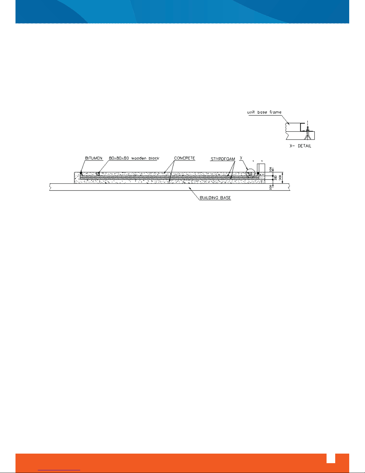
If the air handling unit is to be installed in a place where low vibration and noise is required such as hotels,
hospitals etc it is recommended to install the unit on a floating concrete base, around which is filled with
expanded polystyrene.
4.1 Connection Of Sections
First of all, transport the unit sections to the place where the unit will be installed. Check the sealing strips
for any damage. Replace the strips if there is any damage. The order in which the individual sections are
assembled can be determined from assembly drawings and by following identification labels on each
section ( For example A1-A1, A2-A2 ). In order to reduce vibration, suitable anti-vibration strips may be
placed under the base frame. To connect the sections, follow the instructions below.
4.1.1 Pent A Post Air Handling Units
Once all sections are located in their place in the order they will be assembled, align the sections for air
tightness and to easily fit the section connection bolts.
Fig. 2: Typical AHU concrete base
Page 8
WARNING: Do not use excessive forces to align the sections, because it
may deform the aluminum framework and casing.
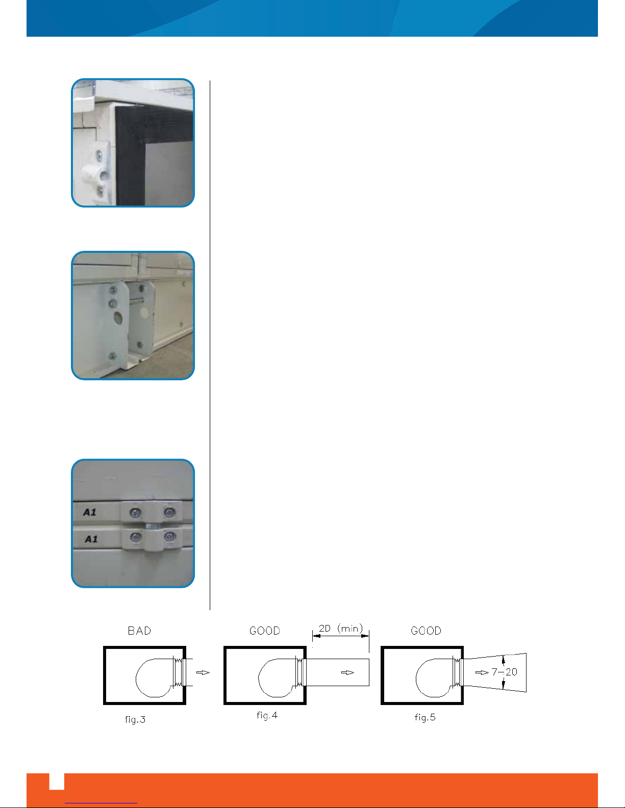
Sections are locked together by special connection parts, bolts, and
nuts. Section connection parts are mounted on the unit sections, bolts
and nuts are fitted on the connection pieces.
First attach the base frame connection bolts on the base frame, and
then section connection bolts and tighten the bolts gradually starting
from the base frame.
4.1.2 Cold Bridge Free Air Handling Units
Cold bridge free air handling unit sections are connected to each other
through the holes on the facing surfaces of the sections and through the
holes on the base frame, by means of bolts and nuts supplied within the
unit. First attach the base frame connection bolts on the base frame,
and then section connection bolts and tighten the bolts gradually
starting from the base frame. And then fit the intermediate cover lids.
5- Connections
5.1- Ducting Connections
Return air, fresh air, exhaust air and supply air should be connected to
the unit by flexible duct connectors. Air tightness should be maintained
to achieve required air flow conditions. Poor ductwork connections to the
unit and incorrect size, shape and arrangement of ductwork fittings can
change airflow conditions.
5.1.1- Free Outlet Conditions
Discharging a centrifugal fan directly to atmosphere (Fig.3) is an
inefficient method of discharge. It can be improved by the addition of a
short duct length coupled to the fan outlet (Fig.4) or by the use of an
expansion section (Fig.5) allowing the air to become less turbulent
before being discharged. This is particularly important when grills or
diffusers are being used at the discharge point as the manufacturers
loss figures are based on a laminar flow air stream and turbulent air
increases the losses.
6
www.doguhvac.com
Air Handling Unit Installation, Operation And Maintenance Instructions
sealing strips
base frame connection
section connection
Page 9
Air Handling Unit Installation, Operation And Maintenance Instructions
www.doguhvac.com
7
5.1.2- Ducted Outlet Conditions
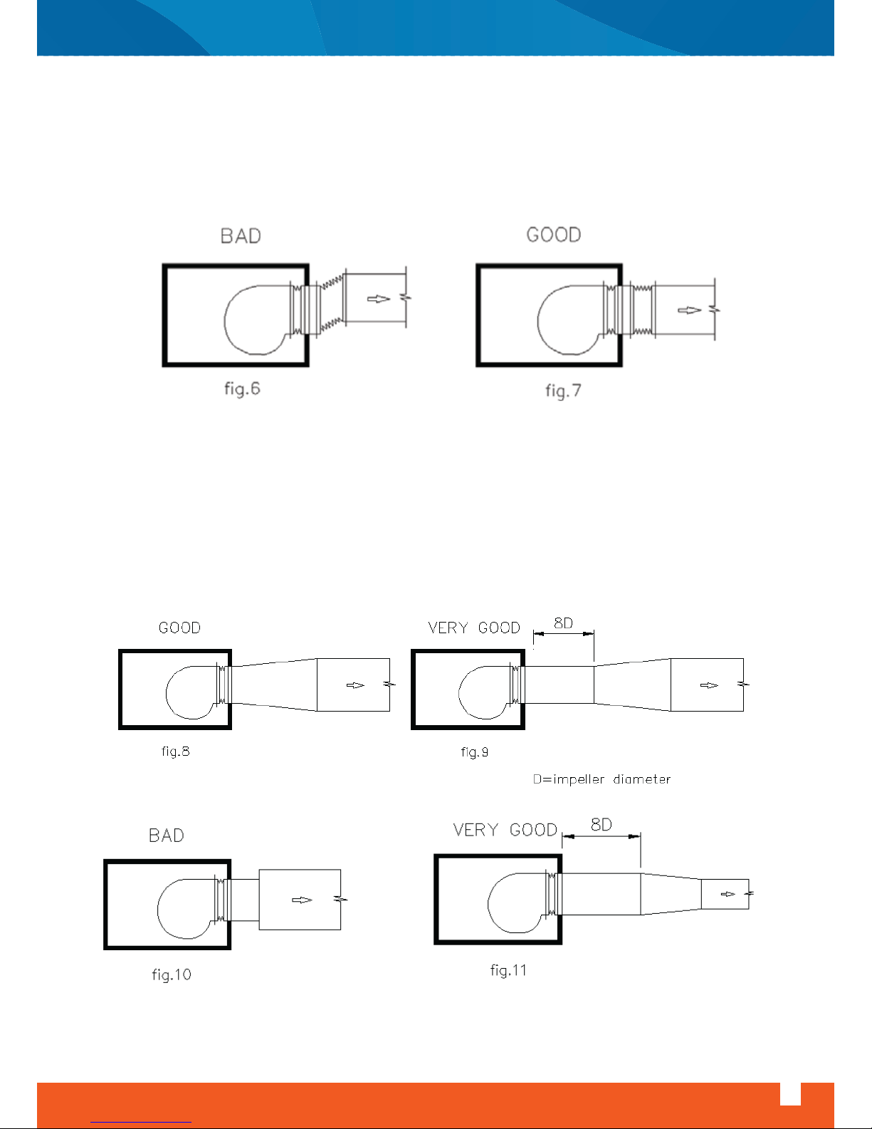
With the outlet connected to the discharge duct by a flexible connector, which is desirable for noise and
vibration isolation, it is important that the connector is correctly fitted. The fan outlet and the duct should
not be misaligned (Fig.6) nor should the flexible connector be allowed to concertina. A smooth passage of
air is desirable at all times. (Fig.7)
When discharging into a duct of larger cross-sectional area than the fan outlet, an expansion section with
an included angle of 7-20ºC should be used. (Fig.8) The ideal configuration is with parallel length of ducting
prior to the expansion section, allowing the air to become less turbulent before expanding. (Fig.9) The fan
should never discharge directly into a duct with larger cross-section. (Fig.10)
The same criteria apply when discharging into a duct of smaller cross-sectional area then the fan outlet. A
ducting section with an included angle of up to 45ºC should be used. Losses will again be minimized if a
parallel section of ducting is used prior to the reducing section. (Fig.11) To achieve ideal conditions the
length of parallel ducting in both cases should be equal to 8 impeller diameters. However parallel ducting of
considerably shorter lengths can be used to advantage
Page 10
8
www.doguhvac.com
Air Handling Unit Installation, Operation And Maintenance Instructions
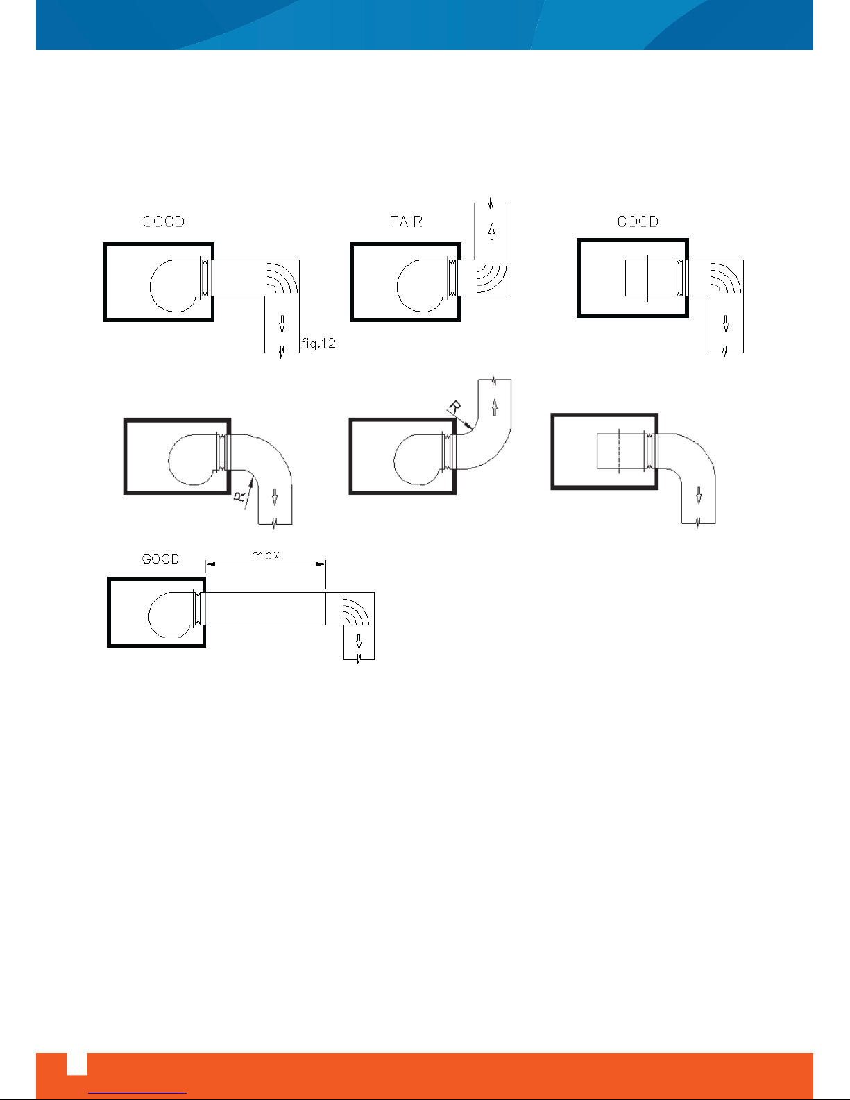
Extremely high losses occur when attempts are made to change the direction of the airflow close to the
fan discharge. If this is necessary the installation should be carried out as in (Fig.12) and ever as in (Fig.13)
A better solution is to have a parallel section of ducting prior to changing direction and it should be as long
as can be accommodated. (Fig.14)
FAIR
BAD
BAD
Fig.13
Fig.14
Page 11
Air Handling Unit Installation, Operation And Maintenance Instructions
www.doguhvac.com
9
5.2- Piping Connections
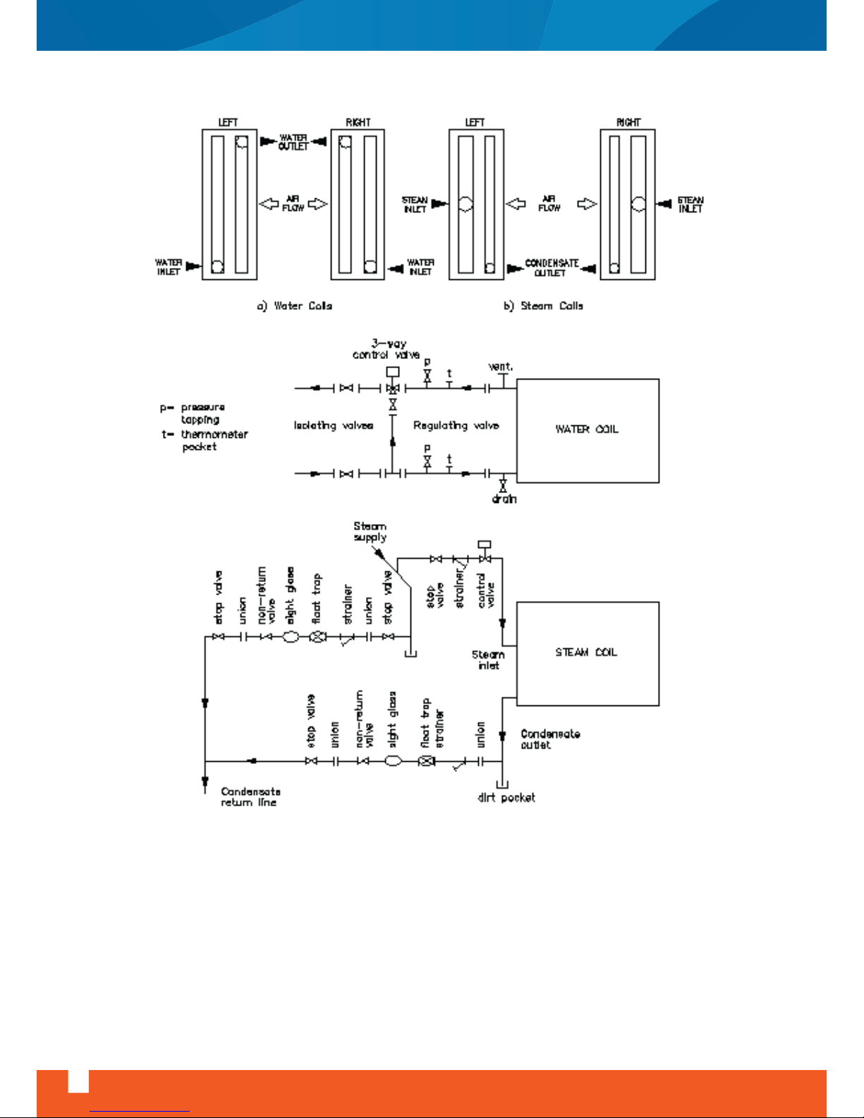
Coils should be piped in counter flow arrangement to achieve required capacity. This arrangement requires
that the entering heating or cooling fluid contacts the air leaving the coil. Water heating and cooling coils
should be arranged with inlet connection at the lowest level on one side of the coil near downstream and
water outlet connection on the same side but at high level near the upstream. This arrangement drives any
air in the system into the upper part of the coil, where a manual air release valve should be fitted.
All coils connecting piping should be independently supported not to impose strain on the coil connections
or circuitry. All coils connecting piping should be thermally insulated
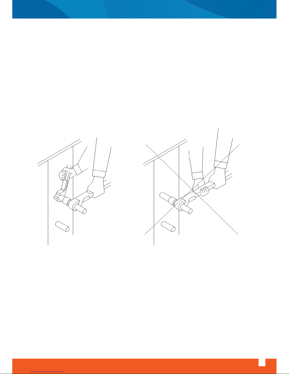
WARNING: Use a pipe wrench to restrain the pipe connections of the coil when tightening the external pipe
connections.
Page 12
10
www.doguhvac.com
Air Handling Unit Installation, Operation And Maintenance Instructions
Page 13
Air Handling Unit Installation, Operation And Maintenance Instructions
www.doguhvac.com
11
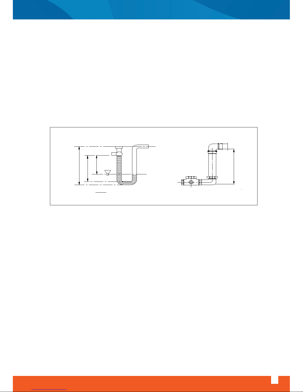
5.3- Condensate Drain Lines
Moisture condensed out of the airstreams on cooling / dehumidifying coils should be drained out of the
unit, to prevent water damage in the air handling unit and ductwork system. Following precautions should
be observed in piping of condensate drain lines.
- Condensate pipe connections to drain pan should not be less than the bore size of the pan outlet connection.
- A union or pipe coupling should be fitted at the pipe connections to the pan to permit easy disconnection
to clean any dirt sediments.
- The siphon (for positive and negative pressure applications) sent by the unit separately should be assembled according to its own installation instructions in the package.
- If the drain pipe is to be long, drain line should be pitched with a gradient not less than 1 in 50.
5.4- Electrical Connections
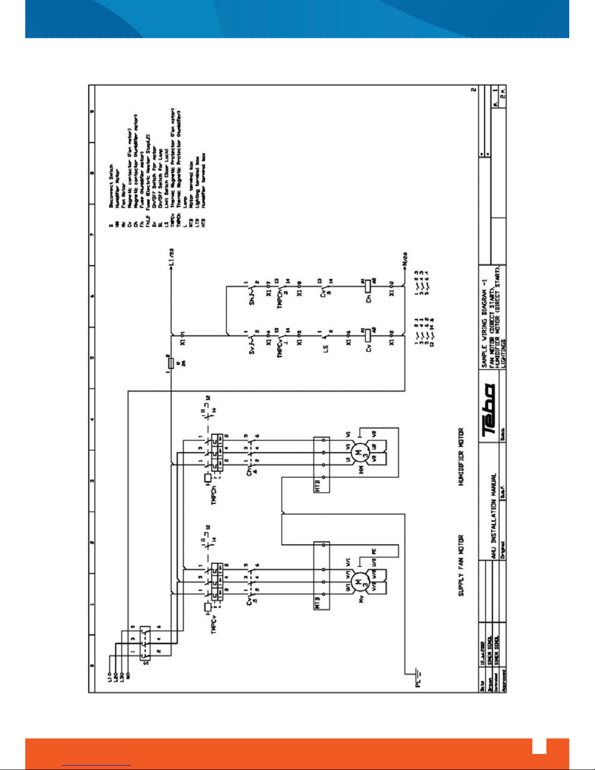
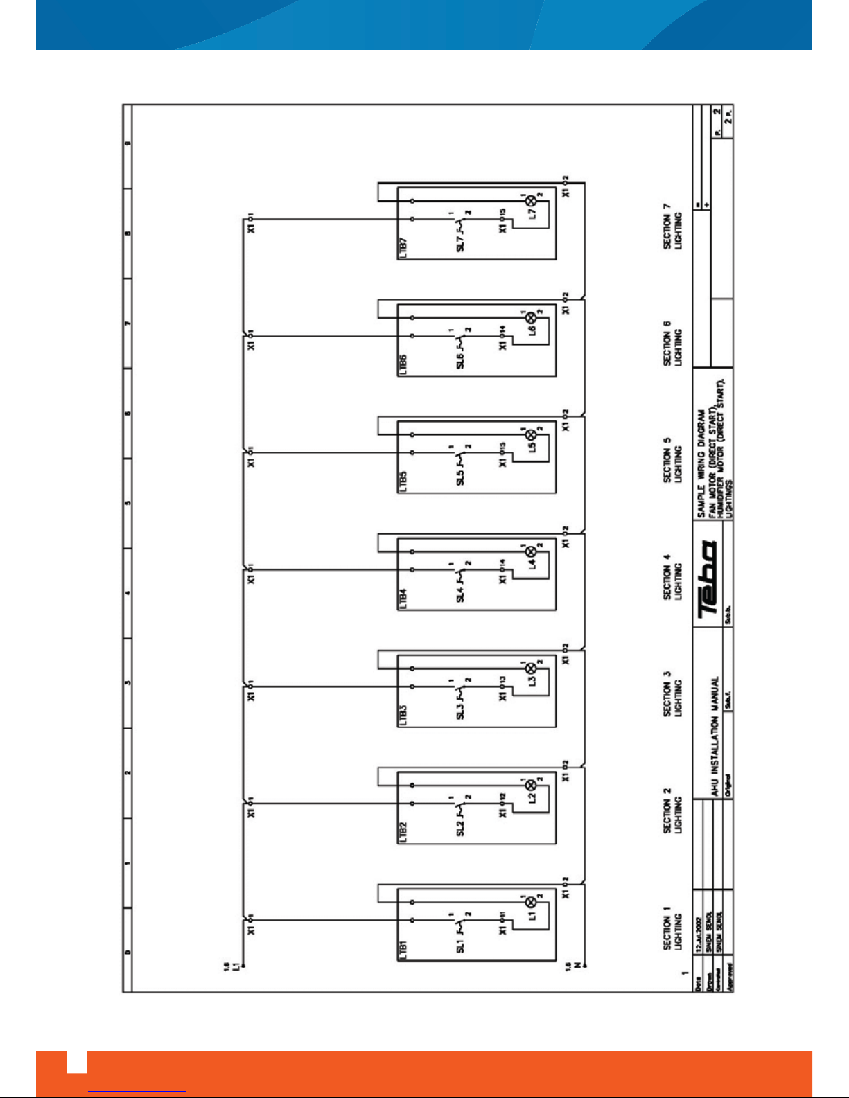
Electric motor, starters, interconnecting cabling and any associated controls should be properly designed
and selected to be suitable for the driven equipment or other electrical apparatus, to be safe and to comply
with the requirements of Electricity Supply Authority. In case of the humidifier and frequency converter
applications their own installation manuals should be used. For the other equipments the installation
instructions and the wiring diagrams which stuck in the terminal box should be followed.
The equipments in the unit except lighting operate with 400V, 3Ph, 50Hz electric supply. Standard lighting
equipment operates with 230V, 1Ph, 50Hz electric supply.
siphon for positive pressure
siphon for negative pressure
H(mm)=
P
10
H + 50 mm
H
1,5 x H
1,5 x H + 60
( ball type siphon )
P= maximum static pressure in unit, Pa
Page 14
12
www.doguhvac.com
Air Handling Unit Installation, Operation And Maintenance Instructions
Starter for centrifugal fans in the air handling units for single speed motors driving through V-belts are
normally of the direct-on-line type. However the customer or Electric Supply Authority may require motors
above 3kW to be operated by a star-delta starter, to reduce starting current.
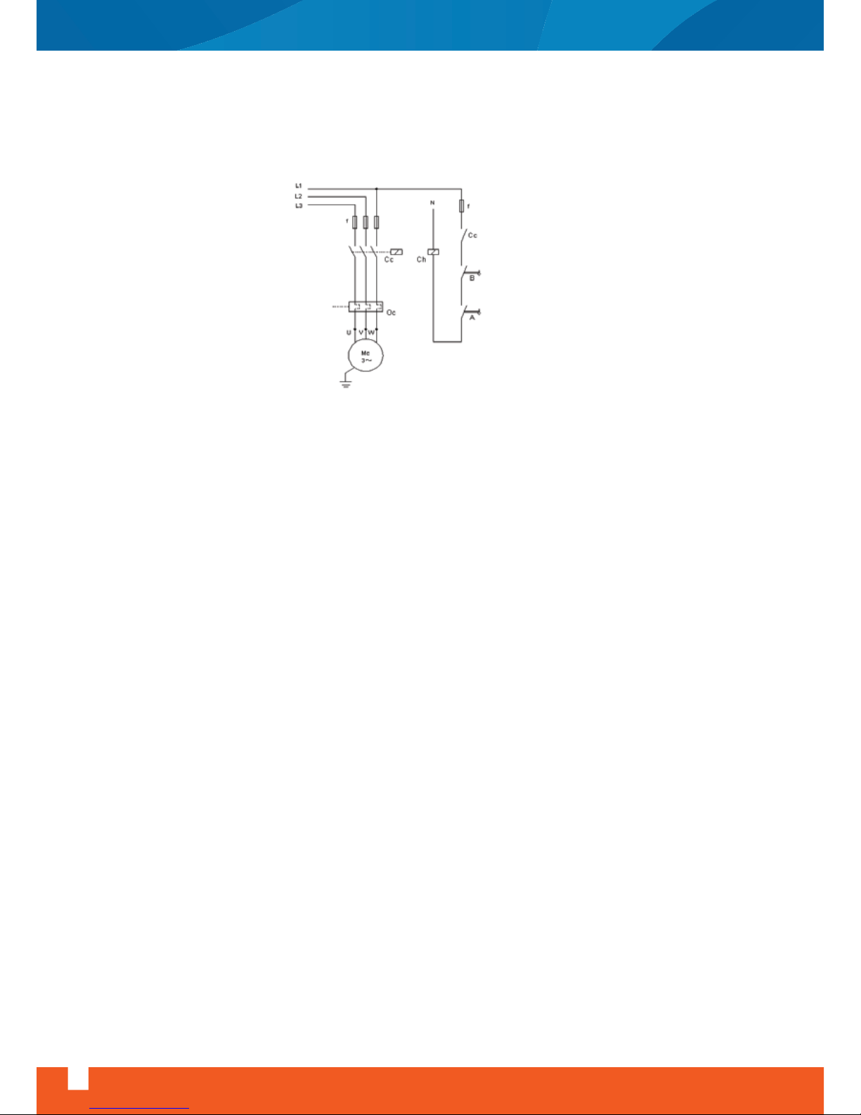
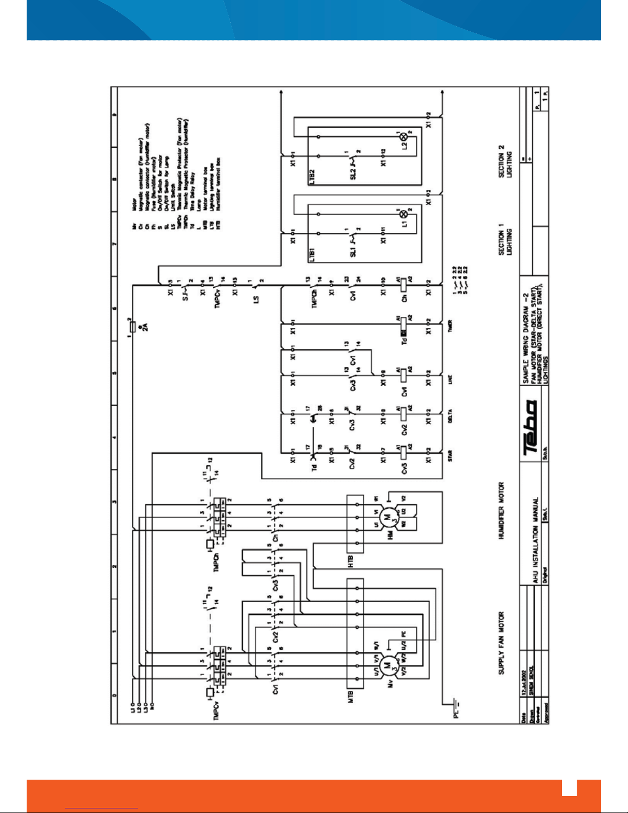
CAUTION: To avoid the electric heater keep on running while the fan is not rotating, the wiring should be
done similar to diagram shown at the right.
WARNING: Electrical installation and wiring works should be carried out by qualified and competent
electricians, in accordance with all international, national and local regulations.
- Thermal overload relay setting
a) Direct-on-line starting: The thermal overload relay should preferably be set to the motor full load current
shown on the motor rating plate.
b) Star-Delta starting: The thermal overload relay should preferably be set to the 0.58 x motor full load
shown on the motor rating plate.
After thermal overload relay settings is done it should be checked that thermal overload relay works
properly at normal operating conditions, by operating motor on two phases.
Motor terminal markings
- The terminal markings of motors conform to the international standards. Stator terminals are marked,
U.V.W and the neutral terminal N.
- Please check data on the rating plate. The voltage marked on the rating plate must be in agreement with
the mains voltage.
The terminal board is normally equipped with 6 terminals. Details concerning the connection are given on
the inside cover of the terminal box and / or on a diagram placed inside by the manufacturer.
- Specifications require that all motors to be earthen properly. Special terminal in the terminal box should
be used for this purpose.
- To avoid the danger of overloading and operation on two phases, the motors should be protected either
with fuses and thermal/thermo magnetic switches or electronic circuits. (See page 37)
- If the electric heater will be used, electrical connections should be done according to the information on
the heater label.
The unit must be installed with a disconnecting device and over current relay on the site if it has not already
equipped.
A Manual reset
B Automatic reset
Page 15

Air Handling Unit Installation, Operation And Maintenance Instructions
www.doguhvac.com
13
The supply cable cross-section-area and length should be selected according to the;
- Motor, lighting, electrical heater, etc power input and electrical supply
NOTE: All power and electrical supply values have indicated on the name plate of the unit and/or name plate
of the equipment except the lighting. Electrical Supply of the lighting is 230V, 1Ph, 50Hz and the power
input of the lighting is 100W as standard. Cable specification from the terminal box to lighting is H05V-K
2x0.75
- Cable installation conditions
- International standards, local rules, regulations and standards and requirements of Electric Supply
Authority.
5.4.1 Converter - Fed Operation Of Motors
When driving motors by a frequency converter, the following must be observed:
- The fan motor must be suitable for operation with a frequency converter.
- Rated speed of motor given on the rating plate should not be exceeded.
- Maximum speed and maximum installed power values for fans given on pages 33 - 34 must not be
exceeded.
- Fan motor must be protected by PTC thermistor against overload and overheating.
- Frequency converter must be overspeed protected.
- Motor PTC thermistor must be wired to the frequency converter by shielded leads.
- Assembly instructions of motor and frequency converter manufacturers must be referred.
- If the operating point of the fan will exceed the design operating point of the fan, there is a risk of motor
to overload and overheat. Please consult to DOGU IKLIMLENDIRME A.S., if the design operating point of the
fan will be exceeded.
WARNING: At very low speeds for converter-fed operation, there is a risk of operation at mechanical
resonance frequency. So, operation of motor at speeds lower than 300 rpm is not recommended.
Programming, first operation and periodic control of frequency converters should be made by qualified
personnel, according to manufacturer’s instructions.
Page 16

Starter for centrifugal fans in the air handling units for single speed motors driving through V-belts are
normally of the direct-on-line type. However the customer or Electric Supply Authority may require motors
above 3kW to be operated by a star-delta starter, to reduce starting current.
14
www.doguhvac.com
Air Handling Unit Installation, Operation And Maintenance Instructions
Page 17
Air Handling Unit Installation, Operation And Maintenance Instructions
www.doguhvac.com
15
Page 18
16
www.doguhvac.com
Air Handling Unit Installation, Operation And Maintenance Instructions
Page 19
Air Handling Unit Installation, Operation And Maintenance Instructions
www.doguhvac.com
17
Page 20

6- Setting Up Of Components
6.1- Dampers
Manually operated dampers can be adjusted to obtain the required air flow, by turning the control lever.
After setting the desired location on locking quadrant, control lever must be tightened. Dampers can be
equipped with the motor. Check that the blades turn back in closed position in case of power supply failure
during operation. Care must be taken to ensure that the actuator does not attempt to push the damper
blades beyond fully open or fully closed positions. All damper blades must be checked for free movement
and for fully open and fully closed positions.
6.2- Filters
Panel filters and zigzag filters are normally fitted within the unit prior to shipping.
Bag filters are normally shipped in closed carton boxes to avoid any collection of dust and loss of efficiency
prior to commissioning. Each bag filter is housed within a special holding frame with necessary locking
spring to ensure proper sealing.
Automatic roll filters consist of basic frame dispensing unit for clean media, rewind unit for dirty media,
drive system, roll filter media and control system. Normally filter media and control system are supplied
loose for site installation. For assembly, filter media roll is mounted on the dispensing unit taken along the
guide channel through working section and locked to the rewind unit. Differential pressure switch must be
installed and connected to the control panel as shown on the circuit diagram.
Absolute filters are shipped in sealed carton boxes. While assembly, special care must be taken to ensure
that each filter cell is properly sealed within the assembly frame with no possibility of air leakage.
Other type of filters such as active carbon filters, sand filters etc. will be supplied with manufacturer’s
instructions along with the units.
Filters that shipped separately in the unit should be assembled after cleaning the inner surface by
operating the fan. Before start-up, check if the filters have been installed.
6.3- Coils
All coils are leak tested and checked prior to assembly. Fins are checked for proper condition. However, they
must be checked once more and combed out if necessary, because they might be damaged during
handling and installation. Do not remove plastic covers from coil pipe connections until the unit is ready for
piping connections. Connections should be checked according to the project. Piping system should be
checked for any damage and leakage. System layout should take into consideration of possible coil
withdrawal.
18
www.doguhvac.com
Air Handling Unit Installation, Operation And Maintenance Instructions
Page 21

It Is Recommended That The Water Flow Is Shut Off When The Fan Is Switched Off. To Avoid The
Overheating Of The Heating Coil, The Hot Water Pump And Water / Steam Valves Should Only Be Opened
During The Operation Of Fan.
Supply Air Control: The Supply Air Temperature Of The Coil At The Suction Side Should Be Max. 40˚c,
Otherwise The Overheating Danger Will Occur.
check The Concentration Ratio Of The Antifreeze Before The Start-up Of The Cooling Coil. It Should Be
Enough For The Claimed Operating Temperature Range. It Should Be Taken In To Account That The
Increasing Concentration Ratio Of The Antifreeze Decreases The Performance Of The Coil.
The Minimum Temperature Of The Chilled Water Should Be +20c, At Lower Temperatures Freezing Danger
Will Occur.
Antifreeze Is A Dangerous Chemical. The Safety Instructions Of The Antifreeze Manufacturer Should Be
Taken In To Account.
Direct Expansion Coils Will Be Supplied With A Refrigerant Distributor Suitable For Brazed Connections.
Refrigerant Pipe Work Must Include Necessary Shut Off Devices, Dehydrators, Solenoid Valves, Oil Traps Etc.
Selection, Sizing, Installation And Setting Of Thermostatic Expansion Valve Should Be In Accordance With
The Recommendation Of Condensing Unit Manufacturer.
Steam Coils: Special Care Should Be Taken For Collection And Disposal Of Condensate Within The Coils And
To Prevent Entry Of The Condensate In The Main Into The Coil By Trapping It Independently On A Coil Bypass.
Condensate Connections To The Steam Trap Must Be Of The Same Size As The Coil Outlet.
6.4- Humidifiers
Mat Type Or Steam Type Humidifiers May Be Assembled In The Unit. For The Piping And Wiring Instructions
Please Refer To Humidifier Manufacturer’s Manual.
The supply water, overflow / drain piping should be done before the start-up of mat type humidifiers. The
supply piping should have a valve for cutting off during the maintenance. Before start-up clean the water
sump, close the drain valve and fill the sump with water. The float adjusts the water level. The distance
between the water level and overflow pipe should be 5cm. The water level in the sump is very important so
that if the water height is usually at low level the humidification performance will decrease. Check the
rotation of the pump, the direction should be at clockwise. Change the connection of the 2 phases if the
direction is opposite. Not to damage the pump do not operate dry.
Before the start-up of the steam humidifier, wiring and piping should be done, steam supply and drain hose
should be connected to the steam distribution pipe.
Before start-up, piping system and hoses should be checked for any damage and leakage.
For further information about the humidifiers please refer to the humidifier manufacturer’s manual.
Air Handling Unit Installation, Operation And Maintenance Instructions
www.doguhvac.com
19
Page 22
6.5- Supply And Return Fans
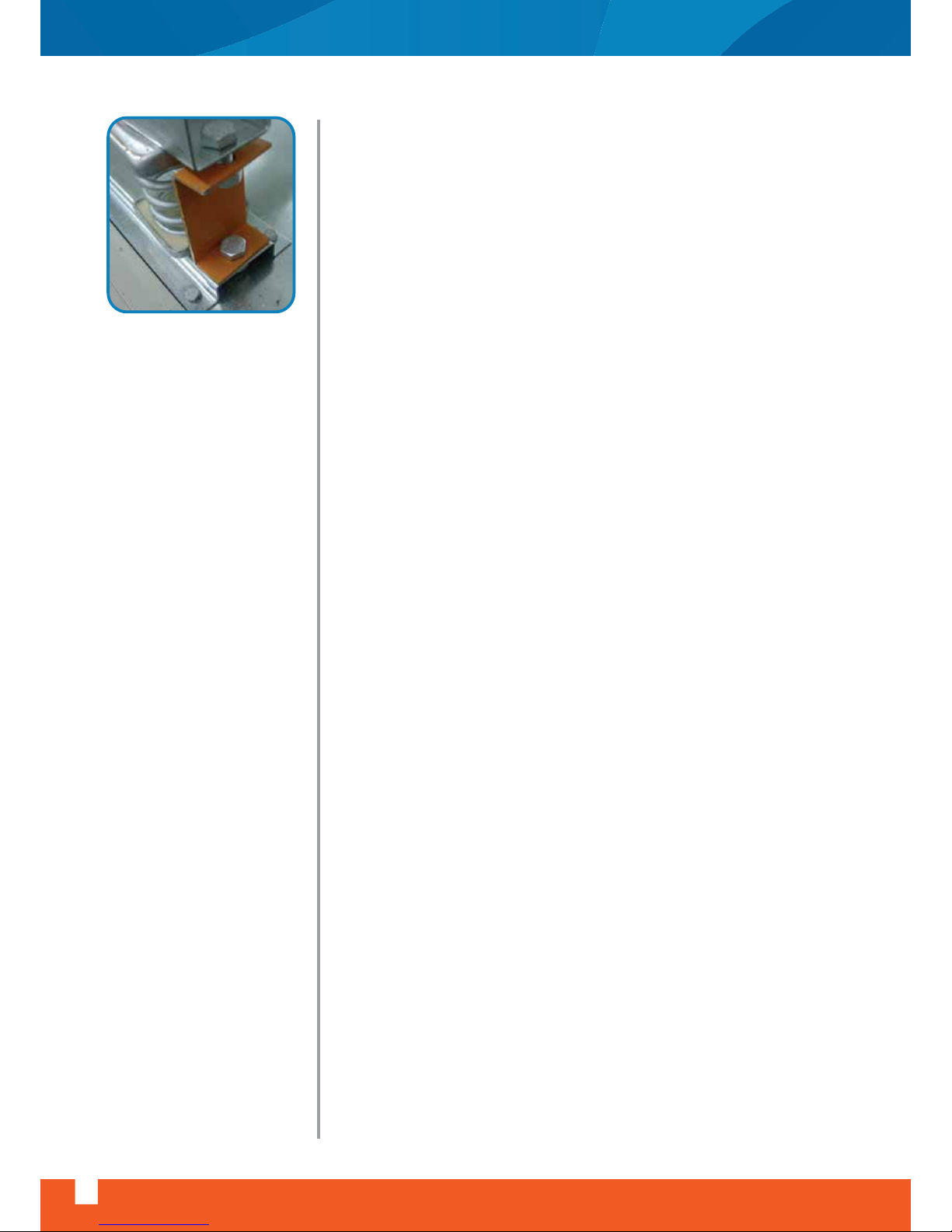
Vibration isolators, on which fan + motor assembly is mounted, are
locked prior to shipping to avoid damage during transport.
WARNING: Once the unit is in position and duct connections are made,
isolators must be released. It should be guaranteed that the fan move
hasn’t locked.
Wiring work must be carried out in accordance with local standards. Type
of start (direct-on-line or star/delta) should met with local electrical
standards. Starters, controls, overload protecting devices, interlocks etc.
should be provided as required. (See page 37) After the start-up, check
that direction of rotation of the fan is correct.
6.6- Electric Heater
The electric heater should be protected against humidity and water. Be
sure that the electric heater automatically cuts off, if the air flow stops.
7- Safety
DOGU IKLIMLENDIRME A.S. air handling units can be considered as safe
machinery. By means of the compliance statement of the EEC and of the
symbol “CE” on the unit, it is guaranteed that DOGU IKLIMLENDIRME A.S.
air handling units fulfill the provisions for the safety and health, on the
ground of Machinery Directive 98/37/EC and the European standards.
The “CE” mark appears on every identification label of the unit.
In spite of all that, the unit can represent a danger, if it is utilized or
serviced not properly or by staff not sufficiently trained, or if it is used not
in conformity with general provisions. For this reason, we intend to
explain to the user the concept of safety referring air handling units and
to inform him of possible danger and consequent measures.
Internal area of the units near to the moving parts (fans, motors, pumps
etc.) end electrical parts, hot sections (hot water and steam coils, piping,
fittings and control devices) are considered as “danger zone”. In order to
be able to access to these
areas, it is necessary to provide one self with the proper key tools. The
operators are responsible for transport, installation, start up, service and
maintenance including cleaning and repairing.
Possible hazards regarding to the air handling units are:
- danger to the operator’s safety
- damages to the unit
- possibility to affect the efficiency of the unit work
isolator locking
20
www.doguhvac.com
Air Handling Unit Installation, Operation And Maintenance Instructions
Page 23

7.1- Use Of The Unit
In order to use the unit according to general provisions, proper instructions of transport, installation and
use must be observed. Installation and start up of the unit must conform to the national standards having
legal course in the country of the user. The user is responsible for compliance with standards. Besides it
must be avoided any type of work that may compromise safety.
WARNING: Arbitrary changes on the unit made by the user or operator are not allowed and exclude the warranty of the manufacturer for the damages to things and persons.
The unit can be started up only by authorized persons and by the means of proper safety devices.
The installer is obliged to install the unit according to installation plans and conditions.
The staff in charge is obliged to signal immediately to the user any changes that may compromise safety.
For this reason it is necessary to inspect the unit for eventual anomalies or damages at least once a week.
The user or operator never must dismount and deactivate safety devices; if these would be removed for
extra maintenance, at the end of the operations they must be reinstalled.
For all operations of extra maintenance, the power source must be locked out and protected against unlock
by anybody else.
7.2- Observation Of Warning Signs
Warning signs should be placed on the unit, showing:
- prohibition to repair or adjust while the unit is running
- obligation to turn off the power before opening the access door
- warning of coming into contact with electrical parts etc.
7.3- Staff Training
Installation, start up and maintenance works can be executed only by authorized and trained staff. This
staff or people who, on behalf of the user, attend to control and make maintenance of the unit must be
informed about possible hazards regarding:
- electrical connections
- piping connections
- ducting connections
- start up
- maintenance
It is necessary to establish and to respect the responsibilities for the control and maintenance to guaranty
safety.
Air Handling Unit Installation, Operation And Maintenance Instructions
www.doguhvac.com
21
Page 24

7.4- Prevent Of Common Dangers And Risks
Air handling units are supplied with locked access doors as an option. So, unauthorized persons are not
permitted to enter the sections which represent a danger.
The most important potential dangers for life and health are described below. The units are manufactured
in conformity with machinery normative 98/37/EC. The user must take into consideration of dangers and
risks described in this manual during operation and maintenance works.
7.5- Recommended Safety Practices
This publication explains the proper use and installation of centrifugal fans in order to warn operating and
maintenance personnel of the commonly recognized dangers associated with this equipment. In addition
to follow the manufacturer’s installation instructions, care must be taken to ensure compliance with
federal, state and local rules, regulations and standards.
Centrifugal fans in air handling units are located inside a casing, so accessibility to the fan is occasional or
infrequent. For this reason, protective devices are offered as optional accessories only at specific user’s
request. However as in case with other machinery involving moving parts, common sense and caution will
preserve personnel safety.
22
www.doguhvac.com
Air Handling Unit Installation, Operation And Maintenance Instructions
KIND OF DANGER
OR RISK
SOURCE OF DANGER
OR RISK
DANGER OR RISK
Danger caused by moving parts Fans, electric motors, pumps Danger of hurting during repair
Danger caused by hot surfaces.
Hot water and steam coils,
steam humidifiers, electric heaters,
electric motors
Danger of burning
Danger caused by pipe or hose
damage
Water and steam coils
Water and steam humidifiers
Danger of burning from hot water or
steam. Danger of electric shock caused
by water contacting electrical parts and
cables Risk of corrosion
Risk caused by mechanical resonance
Vibration isolators
Risk of damage or destruction of air
handling unit components
Risk caused by overspeed of fan
External frequency converter
Risk of damage of motor, fan and
ductwork
Risk of excessive noise
Page 25

The available optional guarding devices are:
1) Fan inlet and outlet guards: Centrifugal fans in air handling units are usually connected directly to ductwork which will prevent the contact with the internal moving parts. In case there is an exposed inlet or
outlet which could represent a danger, suitable guards can be installed.
2) Drive guards: Safety guards should be used when drive systems are accessible by the personnel.
3) Limit switch: Cuts off the power supply of the fan motor when door opens. As the fan keeps on rotating,
do not attempt to enter the unit within minimum 2 minutes, after opening the door.
Also supply disconnecting device and suitable warnings should be used. Maintenance personnel must
engage the disconnecting device before starting any maintenance and repairs; do not forget to protect
against unlock by anybody else.
7.6- The Hidden Danger
In addition to the dangers of rotation machinery, fans present another potential danger by virtue of their
ability to draw in loose material. Solid objects passing through a fan represent potentially dangerous
projectiles. Solid objects can cause fan failure by physically damaging the impeller blades. If the guard is
removed for any reason, the fan must be disconnected and locked out. Where fans are installed over an
occupied area, safety guards should be provided to prevent dropped objects from entering this area during
installation and maintenance.
WARNING: Access doors to a fan or duct system must not be opened when the fan is running or coasting to
a stop. After the unit has switched off, the impeller continues to run for approximately 1-3 minutes. The fan
section is therefore still under pressure and the door must not be opened. Power shall be locked out prior
to access into the fan section or ductwork. Even when locked out electrically, fans may cause injury or
damage if the impeller is subject to “windmilling”. The impeller should be secured to physically restrict
rotational movement. On the downstream or pressure side of the system, attempting to open the access
door while the system is in operation, may result in an explosive opening. On the upstream or suction side,
the inflow may be sufficient to draw in tools and clothing etc. and create a danger.
WARNING: Impeller must never be slowed down by hand or with objects.
The stroboscopic effect of certain lights in combination with certain fan speeds may cause a rotating
assembly to appear stopped.
Noise: At normal operating conditions, noise emission of air handling units does not (with duct connections
made and service doors closed) exceed 70dB (A)
But at extreme operating conditions and depending on room acoustics, noise emission may be dangerous
for health. Prolonged exposure at or above 85 dB (A) requires the use of hearing protection (ear plugs, ear
muffs etc.)
Air Handling Unit Installation, Operation And Maintenance Instructions
www.doguhvac.com
23
Page 26

7.7- Start Up
Before operating air handling unit for the first time (or after an annual maintenance) the manufacturer’s
instructions must be followed. In addition, the following check list must be completed:
- Ensure that all the sections of the unit are thoroughly cleaned. There is a possibility of collection of debris
such as duct insulation materials, tapes, etc.
- Ensure all electrical wiring is carried out in accordance with local standards and all components are
provided with safety, protecting and isolating devices. (See page 37)
- Remove all filters, install low efficiency filters such as gauze bags or throw away type filters, to keep the
filters clean.
- Clean water/steam/refrigerant coils and check pipe connections for any leakage and damages. Ensure
that all the air in the system and in the coil is vented out. Check coil face free from debris.
- Ensure all panels, if removed during installation, are in position and all service doors are closed.
- Ensure that minimum water level is maintained in the humidifier. Check pipe connections and hoses for
any leakage and damages.
7.7.1 Operation Of Fans:
Before operating fans:
- Check that pulleys are secure on shafts.
- Check tightness of belts.
- Check that all moving parts of the fan and motor are free to rotate.
- Check that no loose materials are left near the fan inlet.
- Check that direction of impeller rotation is correct. For this, momentarily energize the fan and see the
direction of rotation.
- Check that fan and motor pulleys are aligned.
- Check if the bearings need lubrication.
- Check that fan and motor are fixed tightly.
- One of the most common causes of motor failure with forward curved blade fans is excessive air flow, due
to overestimated system resistance. To overcome this type of failure, first start-up should be with the main
system damper partially closed and to be opened when correct proportional air flow has been achieved by
system regulation.
- Check that flexible connections are firmly fixed and undamaged, duct connections are designed in
accordance with acceptable engineering practices and with the manufacturer’s recommendations.
- Check that thermal overload relay setting is correct.
- Switch on the electric supply and allow fan to reach full speed. Check carefully for:
• Excessive vibration
• Unusual noise
• Motor current and voltage values
If any problem is indicated, switch of immediately. Lock out the electrical supply, secure fan impeller if there
is a possibility of wind milling. Check carefully for the cause of the problem and correct as necessary.
After ensuring that there is not any problem, no leaks between joints and system is clean, stop the fan.
Dispose low efficiency filters, install panel/bag/absolute filters as supplied. Restart the fan:
24
www.doguhvac.com
Air Handling Unit Installation, Operation And Maintenance Instructions
Page 27

- Adjust damper position to obtain required air volume. Ensure that the air volume is within specified limits.
- Check the motor current and ensure that it is in accordance with the motor rated data (on motor nameplate)
- Check inlet-outlet temperatures across coils and adjust water/steam flows accordingly. Check the functioning of control devices.
- Check the functioning of humidifier by adjusting the humidistat control.
- Check the operation of heating coils by adjusting thermostat. Check the functioning of controls. (air flow
switch, fan interlock, overheat protection, etc.)
- Check the pressure drop across the filters and ensure that it is within limits.
During the first eight hours of running, operation of fan should be periodically observed and checked for
excessive vibration and noise. Motor input current and motor and bearing temperatures should also be
checked to ensure that they do not exceed manufacturer’s recommendations. Then the fan should be shut
down to check the following items and to adjust, if necessary:
- Belt drive alignment and belt tension
- Bearing housing temperature
- Fan and motor fixing bolts
After start up and initial satisfactory operation of two weeks, it is recommended to have the following
checks:
- Belt drive alignment and belt tension
- Motor running current
- Bearing temperature immediately after stop. Bearing temperature should not exceed 70ºC. Lubricate if
necessary.
- Condition of filters
- Condensate and drain, to see flow
- Operation of control devices
WARNING: Investigate any changes to the fan. You may have more detailed explanation of problems and
possible causes in “troubleshooting” section. Consult your manufacturer or other qualified consultant for
questions concerning changes observed during periodic inspections.
- If excessive vibration is observed, stop the fan until the cause is corrected. Check for material build up on
the impeller which causes an imbalance and leads to the fatigue failure or impeller.
- Changes in the sound level of the fan may indicate troubleshooting is required.
- If the motor temperature is high check cooling fan of the motor. It may be blocked or broken. Also check
the input current. An increase in current may indicate that some major changes have been made in system.
- High bearing temperatures usually caused by improper lubrication. If the cause of the problem is not
easily seen, experienced personnel must examine the equipment before running it again.
8- Maintenance
A preventive maintenance program is an important aspect of an effective safety program. Maintenance
works should be performed by experienced and trained personnel. Do not attempt maintenance unless
electric supply has been locked out and the impeller has been secured. Before the maintenance operation,
the safety precautions should be taken by locking out the main and maintenance switch and protecting
against unlocking by anybody else.
Air Handling Unit Installation, Operation And Maintenance Instructions
www.doguhvac.com
25
Page 28

WARNING: During maintenance and repair works that will be done with an operator inside the unit a
prominent ‘MAINTENANCE, DO NOT CLOSE THE DOOR’ sign must be placed on the service door.
Especially at the hygienic air handling units, filters, coils, (by disconnecting the flange connections), droplet
eliminator and sound attenuators can be taken out from the service doors. Besides, all components can be
taken out from the unit for cleaning and disinfection processes.
In general air handling unit do not require special attention other than routine cleaning and maintenance
work. Frequency of maintenance depends on operating conditions. Following is the recommended
maintenance schedule.
Once a week
- Check the conditions of filters every week. Clean, wash or replace if necessary.
- Check the condition of drain for free flow
Once a month
- Check belt drive alignment and tension, adjust if necessary
- Check the condition of float and valve in humidifier
- Check the condition of access door hinges and seals lubricate hinges if necessary.
Once in six months
- Check the motor running current
- Check fan and motor bearings for high temperature and noise
- Check function of control devices.
- Clean condensate drain pan, trap and drain line
- Check air washer circulating pump and motor
- Check the condition of inlet strainer of air washer
- Check the condition of piping system for chilled/hot water or steam for leakage and damage.
- Add chemicals if necessary.
Once a year
- Check the filter frame for proper sealing
- Replace synthetic filter media in panel filters.
- Check the controls and operation of automatic roll filters
- Check the coils and fins. Wash with water spray, if necessary.
- Check the coils for any leakage
- Went the water coils
- Replace belts
- Check the tightness of the fan and the motor fixing bolts
26
www.doguhvac.com
Air Handling Unit Installation, Operation And Maintenance Instructions
Page 29

Air Handling Unit Installation, Operation And Maintenance Instructions
www.doguhvac.com
27
- Check motor and fan bearing lubrication
- Check the operation of dampers
- Check the condition of access door for easily opening and proper locking
- Check the condition of valves and fittings on the piping system
- Check all wiring, control and isolating devices, terminal connections, etc.
After inspection and replacements, if necessary proceed in accordance with operation instructions, before
running the unit again.
Following must also be noted about maintenance works:
A) Fan Sections
For detailed information about lubrication of bearings, belt tension and alignment controls, changing of
pulleys, see related sections in this manual.
B)Coil Sections
Coils should be cleaned to remove any accumulation of dust between the fins and tubes should be checked
for any leakage. Cleaning process can be done in 3 ways;
- vacuum cleaning
- compressed air
- water or steam spray (opposite to the air flow direction)
CAUTION: During the application, the water, steam or air pressure should not exceed 5 bars.
To clean the cooling coil at the hygienic air handling units, the coil can be reached from both sides by taking
out the droplet eliminator from the service door by disassembling the by-pass sheet metal. With the same
principle as there’s no droplet eliminator, the heating coil can be cleaned by reaching both sides from the
service doors.
If it is required to withdraw the coil for cleaning and repairing, proceed as follows:
- drain the water inside the coil
- disconnect the coil from piping connections
- remove the side panel
- remove the bolts by which coil is fixed
- withdraw the coil
To check for leakage in the tubes,
- clean and dry the coil
- fill water inside the tubes
- see where the leakage is
- drain the water inside the coil
After cleaning the coil, drain should be checked and the siphon should be cleaned.
Page 30

CAUTION: Keep coils from freezing. When water inside coils is allowed to freeze, serious damage will be
caused to the tubes. So, if there is a danger of freezing, anti-freeze chemicals should be added to the
circulating water or if the coil will not be operated for a short time, some water circulation should be
provided inside the tubes. If the coil will not be operated for a long time, it is recommended to drain to coil.
C) Filter Sections
Condition of the filters should be checked once a week. Dirty filters reduces the air flow and hence the
capacity. A manometer, measuring filter pressure drop should be fitted to filter section. If other not stated
on the unit, please use the recommended maximum pressure differentials for different kind or filters that
are given on below table. When manometer reading shows these values, filters should be cleaned or
replaced, and these values should not be exceeded. Synthetic or metallic filter media can be cleaned or
washed. However it is recommended to replace synthetic media in every two years. New filters should be
assembled in the right position that the rough and open side looks to the dirty air, smooth face to the clean
air side.
If there’s gasket on the previous filter frame, to achieve the necessary tightness do not forget to apply the
same media (absolutely same way) on the new filter after renewal.
Other type of filters such as throw away media, bag, absolute and roll filters must be replaced with new
filters of same type, size and efficiency.
After opening the service door, the filters can be taken out by pulling aside.
Synthetic bag filter can be cleaned by vacuumed or compressed air besides can be washed with the
sensitive detergent and warm water.
28
www.doguhvac.com
Air Handling Unit Installation, Operation And Maintenance Instructions
FILTER GRADE
INITIAL PRESSURE
DIFFERENTIAL
RECOMMENDED MAXIMUM
PRESSURE DIFFERENTIAL
G-2
G-3
G-4
25 Pa
40 Pa
50 Pa
150 Pa
150 Pa
150 Pa
Table 2: Pressure differentials for panel filters
FILTER GRADE
INITIAL PRESSURE
DIFFERENTIAL
RECOMMENDED MAXIMUM
PRESSURE DIFFERENTIAL
G-4
F-5
F-6
F-7
F-8
65 Pa
55 Pa
60 Pa
115 Pa
165 Pa
150 Pa
250 Pa
250 Pa
250 Pa
350 Pa
Table 3: Pressure differentials for bag filters
Page 31

Air Handling Unit Installation, Operation And Maintenance Instructions
www.doguhvac.com
29
D) Humidifier sections
Humidifier should be cleaned regularly. The period changes according to the operating conditions, air
specifications and water quality. During periodic maintenance of humidifier, checks mentioned in its own
manual should be performed. Piping system and hoses should be checked for leakage and damage.
E) Sound Attenuators
Sound attenuators can be taken out from the service door by unscrewing the components from the top and
bottom panels. Attenuators can be cleaned by vacuumed or compressed air.
F) General
Periodic checks should be made for thermal and acoustic lining and electrical insulation of the unit
sections. Also connecting cables and control panels should be checked. Any metal surface which shows
signs of deterioration should be cleaned.
Bolts, nuts and other assembling elements should be checked. Any missing bolts, nuts and screws should
be replaced.
To clean the damper compressed air can be used. Do not lubricate the shaft of the damper.
Impurities on the droplet eliminator blades should be cleaned regularly. The period changes according to
the operating conditions and the air quality. As cleaning media any de-scaler available on the market can
be used.
For the best cleaning process of the droplet eliminator at the hygienic air handling units it should be taken
out from the unit and disassembled by unscrewing.
To clean the inner surface of the unit (after necessary components taken out) water / steam spray and
cotton or directly wet cotton can be used by wiping.
9- Belt Tension And Alignment Control
Tension of the belt is adjusted at the factory. But after the first day operation and later approximately at
one month intervals, belt tension should be checked and adjusted if necessary. To check the belt tension:
- Measure centre distance of pulleys. (in meters)
- Calculate belt deflection by using the following formula
Belt deflection (mm.) = centre distance (m.) x 16
- Measure the force required to obtain the calculated belt deflection by using a belt tension checker. Place
belt tension indicator on top of the belt and at the center of the span. Apply force at right angle to belt.
- Compare the measured force with the values given on the following table. If the measured force is within
the range, belt tension is satisfactory. If it is below the lower value, belt needs tensioning.
Page 32
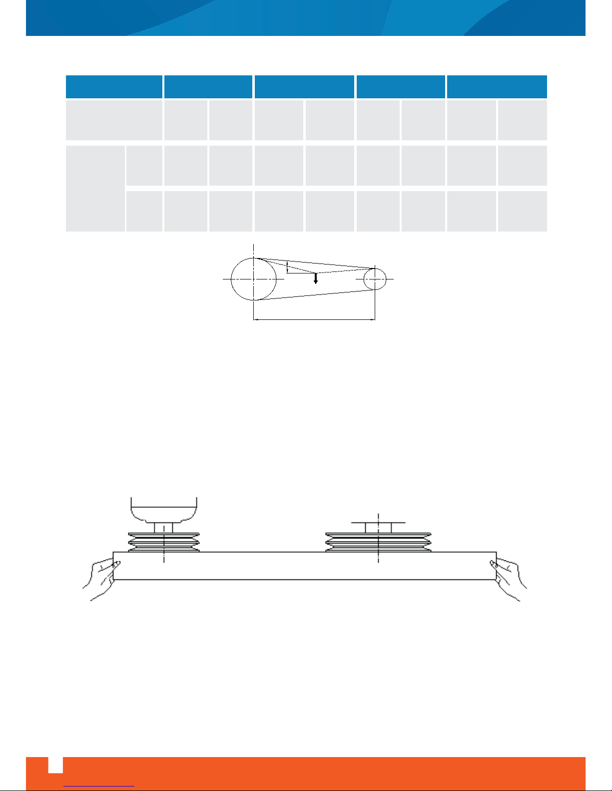
Before locking the motor is position, check the alignment of pulleys with a straight edge to conserve belt
life as well as to eliminate the possibility of unnecessary noise.
If the belt is not tight enough, and if not corrected, could result in slippage causing loss of fan speed and
belt failure through wear.
If the belt is too tight, and if not slackened somewhat could cause noise from excessive vibration,
premature bearing failure and shorter belt life.
Efficiency is another reason to properly adjust belt tension. Excessive belt tension can create such a power
demand as to actually overload a motor that otherwise would be quite adequate.
A belt should be just tight enough to avoid slippage.
30
www.doguhvac.com
Air Handling Unit Installation, Operation And Maintenance Instructions
Belt section SPZ SPA SPB SPC
Small pulley diameter,
mm
56
to
95
1,3
to
2,0
100
to
130
2,0
to
2,5
80
to
132
140
to
200
112
to
224
236
to
315
224
to
355
375
to
560
2,5
to
3,6
3,6
to
4,6
4,6
to
6,6
6,6
to
8,7
8,7
to
11,7
11,7
to
15,3
13
to
20
20
to
25
25
to
35
35
to
45
45
to
65
65
to
85
85
to
115
115
to
150
Tensioning
force,
F
kg
N
DEFLECTION
CENTER DISTANCE
F
SMALL
PULLE
Y
Page 33
Air Handling Unit Installation, Operation And Maintenance Instructions
www.doguhvac.com
31
10- Change Of Pulleys
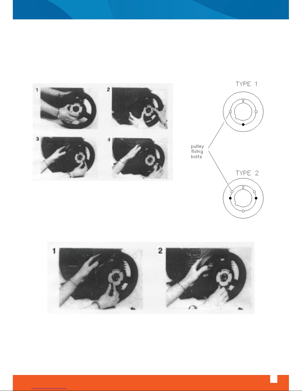
10.1- Mounting Of Pulleys
- Clean and degrease smooth surfaces of bushing, pulley and shaft
- Assemble bushing and pulley by aligning semi-threaded holes. Insert the screws loosely.
- Insert the key on shaft, then slide pulley to desired position with screw heads to the outside.
Tighten screws evenly and progressively. Never apply extreme tightening forces.
10.2- Removal Of Pulleys
- Remove tightening screws
- Insert one of the screws in the semi-threaded hole and tighten until bushing becomes loose on shaft.
Page 34
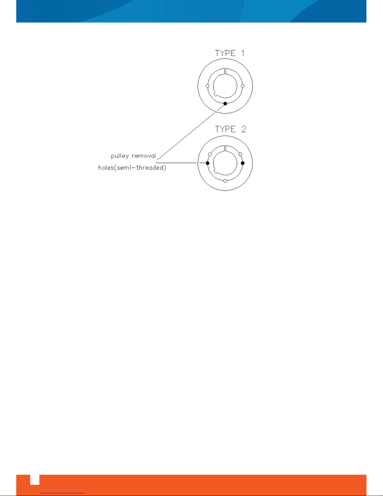
CAUTION: Don’t use hammer or puller to remove the pulley. Don’t change pulleys without written consent
of DOGU IKLIMLENDIRME A.S.; otherwise we take no responsibility for the consequences.
11- Lubrication Of Bearings
Bearings have to be controlled and cleaned regularly; have to be lubricated adequately to prevent direct
metallic contact between rolling elements, to prevent wear and to protect bearing surfaces against corrosion.
The fans with low shaft power are equipped with bearings in a rubber housing which absorbs a part of vibration. When you change the bearing it is very important to change the rubber housing too. These bearings
don’t need to be lubricated.
The fans with higher shaft power are equipped with bearings with cast iron support. The lubricant filled in a
bearing gradually loses its lubricating properties during operation. Therefore it is necessary for grease to be
replenished or renewed from time to time. The grease used is always lithium soap type suitable for all temperatures within the operating range.
Excess grease will cause the operating temperature to rise rapidly, particularly when running at high
speeds. Therefore only the bearing should be completely filled, whilst the free space in the housing should
be partly filled (between 30 and 50 %) Where bearings are to operate at very low speeds and must be well
protected against corrosion, it is advisable to completely fill the housing.
Some of the bearings are prelubricated for life, that means grease life is tailored to the bearing life. Life of
regreasable bearings can be increased by observing specified relubrication intervals; this can also compensate for other factors such as temperatures, ingress of liquids, speed, bearing size and mechanical
load.
32
www.doguhvac.com
Air Handling Unit Installation, Operation And Maintenance Instructions
Page 35

Air Handling Unit Installation, Operation And Maintenance Instructions
www.doguhvac.com
33
CAUTION: For lubrication of bearings refer to the recommendations of fan and motor manufacturers.
12- Troubleshooting
Before checking the fan system, it will be necessary to shut down the fan. During inspection, the unit must
be isolated electrically and all disconnect switches and other controls must be locked in the “off” position.
Also, a prominent “DO NOT START” sign should be placed on control panel.
To find out the problem is an important step to correct it. By following the procedures outlined in this
section, cause of the problem should be found.
Procedure for troubleshooting:
a) Look at the troubleshooting chart to find the problem. Check probable causes.
b) If the cause of the problem can not be found proceed through the “system checklist.
c) If the problem still can not be solved, it is recommended to contact the “unit manufacturer”
System checklist
A systematic check of items listed below may identify the problem. See that:
a) Impeller rotation is correct
b) Pulleys are aligned
c) Belts are not loose or too tight
d) Belts and/or pulley are not worn.
e) Flow surfaces of fan (impeller blades, housing and passages between inlets) are clean.
f) Impeller and housing are not damaged.
g) Coils, filters, ducts are clean.
h) Fan outlet connections are correctly designed and installed.
i) Variable inlet vanes are synchronised. If inlet vanes are not synchronised, there will be an unbalance flow
between inlets causing thrust on bearing and low performance.
j) Inlet vanes are correctly positioned for the designed operating conditions
k) There is no leak in the unit and ductwork. Some common leak sources are access doors, coil, duct joints,
fan outlet connections etc.
If the cause of the problem still can not be found, consult air handling unit manufacturer. Manufacturer
may need following information
a) Complete drawings including unit location, ductwork detail, model and size of the unit.
b) Measured and design performance figures.
c) System design calculations
d) Measured fan performance figures such as fan static pressure, air volume, current drawn, fan speed, air
temperature and altitude etc.
Page 36
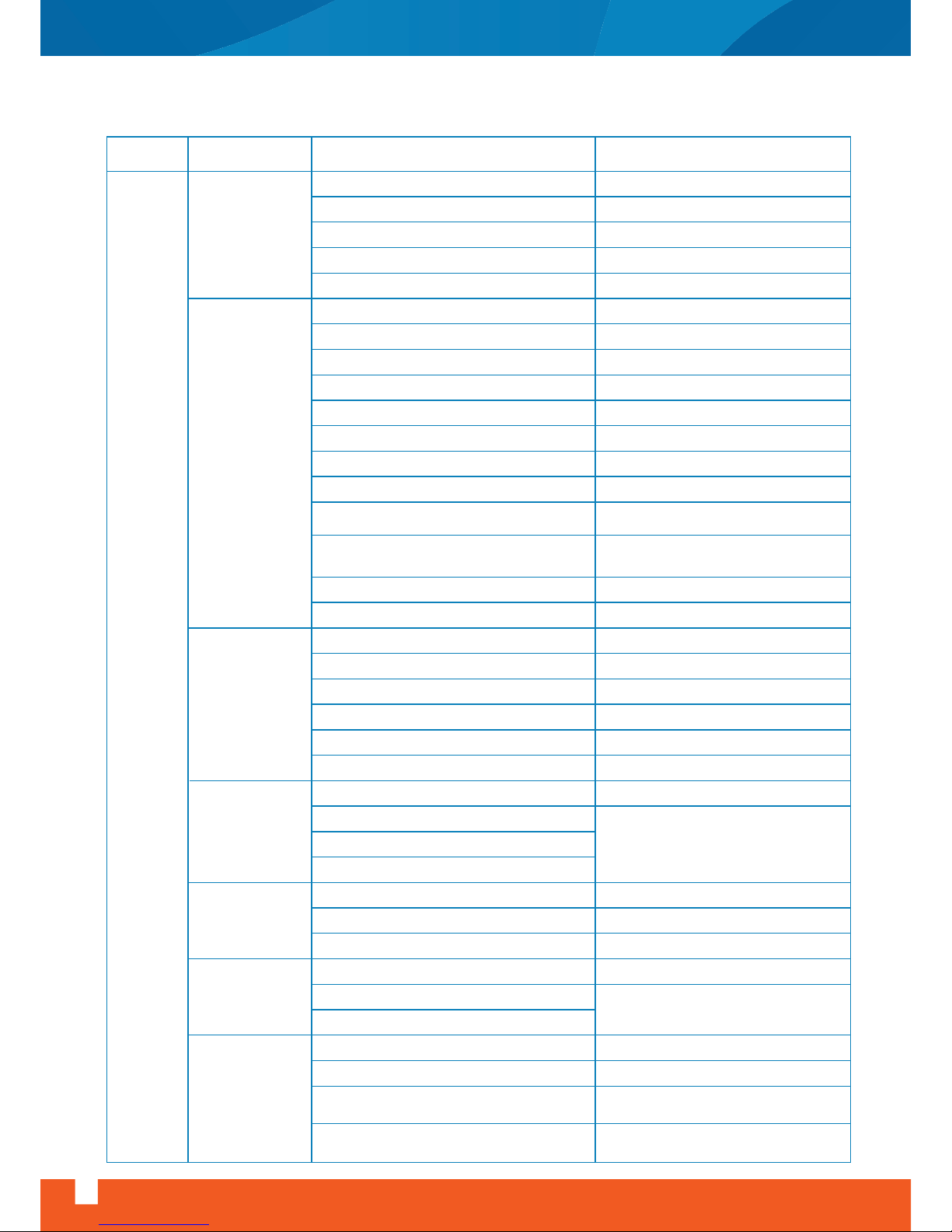
12.1- Troubleshooting Chart
PROBLEM
NOISE
Impeller hits inlet
ring
Damaged impeller
Damaged inlet ring
Impeller not centered on shaft
Shaft loose in bearing
Impeller loose on shaft
Correct or change impeller
Correct or change inlet ring
Center the impeller
Tighten shaft
Tighten impeller
Belts too loose
Belts too tight
Belts wrong section
Belts worn
Belts oily or dirty
Belts length different (multibelt drives)
Drive systems hits drive guard
Fan, motor or motor base fixing bolts loose
Pulleys misaligned.
Variable speed pulleys not adjusted so each
groove has different diameter.
Motor bearings damaged
Loose on support
Loose on shaft
Bearings worn or damaged
Bearings need lubrication
Foreign material inside bearing
Corrosion between shaft and bearings
Tighten bearings
Tighten shaft
Change bearings
Lubricate bearings
Clean bearings
Clean corrosion, if the shaft worn change shaft
Ductwork undersized for application
Fan size is too small for application
Check duct size and revise if necessary
Change size of equipment, revise if
necessary
Coil with insufficient face area
Worn or damaged impeller
Unbalanced impeller
Foreign material in fan housing or inside the unit
Change impeller
Balance impeller
Clean fan housing
Vibrating ductwork
Vibrating casing parts
Stiffen ductwork
Isolate vibrating parts properly
Vibrating parts not isolated from building
Obstruction in dampers, registers, grilles
Leaks in casing and ductworks
Sharp elbows
Sudden expansion or reduction in ductwork Install expansion/reduction sections with
proper expansion/reduction angles
Check and remove any obstructions
Seal leaks
Remove sharp elbows, install elbows with
proper radius and turning vanes
Registers and/or grilles undersized for application
Fan shaft bent
Belts too loose
Adjust belt tension
Install correct section belts
Change belts
Clean belts
Install correct belts.
Check drive system and drive guard.
Tighten bolts
Align pulleys
Adjust each groove to same diameter for
required air flow
Change bearings
Correct or change shaft
Noise from drive
system
Noise from
bearings
High air velocity
Noise from impeller
Vibration
Rattling/whistling
SYMPTOMS POSSIBLE CAUSE OTHER CAUSES OR ACTION
34
www.doguhvac.com
Air Handling Unit Installation, Operation And Maintenance Instructions
Page 37

Air Handling Unit Installation, Operation And Maintenance Instructions
www.doguhvac.com
35
NO AIR FLOW
Motor is not
running
Motor is runni
ng but no
air flow
LOW AIR
FLOW
HIGH AIR
FLOW
HEATING
COIL
No heating
HEATING COIL
Low heating
Current is not
reaching motor
Current available
to motor
Fan is not running
Fan is running
Electric power failure
Motor bearing seized
Incorrect wiring to terminals
Faulty motor windings
Impeller loose on shaft
Duct blockage
Impeller loose on shaft
Filters are dirty or clogged
Coils are dirty or clogged
Fan rotation is not correct or impeller
installed backwards
Belts are not tight or are greasy
Drive belts are slipping
Duct resistance exceeds design criteria.
Poor duct design
Dampers/registers closed
Access doors are loose. Duct joints are
unsealed. Outlet duct system is not completed
High leakage on pressure
side of the system
Drive system is wrong. Fan speed is low
Ducts are oversized or duct resistance
overestimated.
Access doors are loose. Duct joints are
unsealed. Suction duct system is not
completed.
Drive system is wrong. Fan speed is high
Supply voltage is low
Registers/grilles not installed
Filters are not installed
Power failure
Air lock
Automatic valve is closed
Isolating valves are closed
Boiler flow temperature is low
Regulating valves are partially closed
Pump failure. Thermostat failure. Time clock
error. Fuel blockage.
Blockage in coil or pipes
Thermostat failure, valve motor failure
Circuit valves are closed.
Thermostats should be adjusted. Boiler power i
s in adequate
Pumping power is not sufficient.
Pipe sizing is not correct. Blockage in coil.
Boiler plant is off
Heating fluid is off
or cold
Heating mains is
cold
Heating fluid flow
rate is low
Filters are clean so low initial pressure
differential
High leakage on
suction side of the
system
Motor current is
excessive
Close balancing dampers or slow down fan by
changing pulleys
Check access doors and duct joints. Seal leaks.
Complete duct system
Consult manufacturer to check whether drive
system is properly selected or not
Motor overloads. Check current drawn by motor
Install registers/grilles
Install filters
Regulate on dampers
Change or clean filters
Change or clean coils
Correct fan rotation, check that impeller is
properly installed
Tighten belts, clean the grease
Check duct pressure losses and duct design
Adjust dampers/register for required air flow conditions
Check access doors and duct joints. Seal leaks.
Complete duct system.
Consult manufacturer to check whether drive
system is properly selected or not
Starter overload tripped
Control panel fault
Isolating switches off
Locate fault and restore power
Faulty wiring motor. Loose terminals.
Locate and correct fault.
Time clock error
SYMPTOMSPROBLEM POSSIBLE CAUSE OTHER CAUSES OR ACTION
Lack off correct lubrication
Motor internal wiring fault
Overheating or overloading incorrect electric supply
Tighten impeller, check the belts
Rubbish blocking duct
Tighten impeller
Page 38

PROBLEM
Cooling fluid
temperature is high
Insufficient
coolant flow
Cooling coil is
partially frozen
No air flow
Safety devices
stops compressor
Safety devices
stops compressor
Faulty thermostatic gear
AIR WASHER
Low
humidifying
COOLING OIL
No cooling
No cooling
ELECTRONIC
STEAM
HUMIDIFIER
No
humidifying
ELECTRONİC
STEAM
HUMIDIFIER
Low
humidifying
ELECTRICAL
HEATER
Low heat
Low water flow
Low water level in water pan
Water distribution system is clogged
Strainer is clogged
High air flow
Refrigeration plant cycles on-off
Refrigeration plant capacity is insufficient.
Circulating pump or compressor fault.
Excessive heat gain in piping system.
Low load
Low suction temperature
Low air flow
Entering air temperature is too low
Thermostatic valve is closed
Power is not reaching elements or
control valve
Electronic power
failure
Heater elements
faulty
Faulty thermostat
gear
Steam supply rate
is low
Steam cylinder and
heating elements
are scaled
Safety cut-out tripped
Humidistat calibration is not correct
Steam-trap faulty
Electric power failure
Main contactor de-energized
Elements down to earthElement failure Elements disconnected / elements incorrectly
wired / wrong voltage
Controller cams faulty / wiring fault / equipment fault
Step controller is sticking
Thermostat set is too low
Thermostat set is too low
Power is not
available at
controller
Power available at
controller
Step controller faulty
Locate fault and restore power
Safety cut out tripped / poor duct design adjacent
to heater causes areas of uneven air velocity and
overheating of casing
Water treatment is insufficient
Heater elements
faulty
Humidistat setting
is not correct
Water is not
available in cylinder
Safety cut-out tripped
Control fault
Chilled water isolating
valves are closed
Cooling thermostat setting is high
High pressure cut-out disconnects
Solenoid valve closed. Low pressure
cut-out disconnects
Valves are partially closed or blockage
in the system
Refer to “no cooling, safety device stops
compressor” section
Refer to “ low air flow” section
Apply reheat or preheat
Unequal air velocity. Poor duct connections
Circulating pump or compressor fault
Blockage in system. Valves are closed. Leakage in piping
Float valve is off. Supply water is off.
Clean the system.
Clean the strainer
Refer to “high air flow” section
SYMPTOMS POSSIBLE CAUSE OTHER CAUSES OR ACTION
36
www.doguhvac.com
Air Handling Unit Installation, Operation And Maintenance Instructions
Water make-up failure or insufficient water level
in cylinder. Water treatment is required to avoid scaling.
Control valves are not opening fully. Manual
valves or partially closed
Manual valves or partially closed
Carry out maintenance or replacement
Thermostatic gear fault
Reset humidistat correctly
Check supply system
Water make-up failure or insufficient water level
in cylinder. Water treatment is required to avoid scaling.
Thermostatic failure. Circulating pump failure
Refer to “no air flow” section
Locate and correct fault
Fault in condenser. Fans or pumps stopped.
Condenser blocked. Heat rejection is not taking place.
Suction temperature is too low. Low airflow.
Entering air temperature is too low.
Oversized coil or compressor.
Page 39

13- Operating Limits Of Fans
WARNING: It is not permitted to operate fans at higher speeds other than design speed, without written
permission of DOGU IKLIMLENDIRME A.S., since operating at higher speeds may overload and damage the
motor and fan.
FAN TYPE
ADH
MAXIMUM
INSTALLED
POWER
kW
MAXIMUM
SPEED
rpm
160L, 160R
180L, 180R
200L, 200R
200K
225L, 225R
225K
250L, 250R
250K
280L, 280R
280K
315L, 315R
315K
315K1
355L, 355R
355K
355K1
400L, 400R
400K
400K1
450L, 450R
450K
450K1
500L, 500R
500K
500K1
500K2
560L, 560R
560K
560K1
560K2
630L, 630R
630K
630K1
630K2
710K
710K1
710K2
800K
800K1
800K2
900K
900K1
900K2
1000K
1000K2
3
3
4
4
4
4
4
7.5
5.5
11
5.5
11
18.5
7.5
15
22
7.5
15
22
11
15
30
11
15
30
37
15
18.5
30
45
15
18.5
30
45
22
37
55
22
37
55
30
45
75
37
75
4200
4000
3800
3800
3400
3400
2800
3000
2500
2700
2100
2400
2400
1800
2000
2000
1600
1800
1800
1400
1500
1500
1200
1300
1400
1400
1100
1200
1300
1300
900
1000
1100
1100
850
900
900
750
800
800
650
700
700
600
650
Air Handling Unit Installation, Operation And Maintenance Instructions
www.doguhvac.com
37
FORWARD CURVED BLADE FANS, TYPE “ADH”
Page 40

38
www.doguhvac.com
Air Handling Unit Installation, Operation And Maintenance Instructions
FAN TYPE
ADH
MAXIMUM
INSTALLED
POWER
kW
MAXIMUM
SPEED
rpm
180L, 180R
200L, 200R
200K
225L, 225R
225K
250L, 250R
250K
280L, 280R
280K
315L, 315R
315K
315K1
355L, 355R
355K
355K1
400L, 400R
400K
400K1
450L, 450R
450K
450K1
500L, 500R
500K
500K1
500K2
560L, 560R
560K
560K1
560K2
630L, 630R
630K
630K1
630K2
710K
710K1
710K2
800K
800K1
800K2
900K
900K1
900K2
1000K
1000K2
2,2
3
3
4
4
4
5.5
5.5
7.5
5.5
7.5
11
7.5
11
15
7.5
15
22
11
15
30
11
15
30
37
15
18.5
30
37
15
18.5
30
45
22
37
55
22
37
55
30
45
75
37
75
6800
6000
6800
5800
6000
4600
5400
4000
4700
3500
4100
4500
3300
3800
4000
2700
3100
3500
2500
2800
3200
2100
2350
2650
2800
1950
2100
2400
2600
1600
1700
2000
2300
1500
1700
2000
1200
1400
1650
1100
1250
1500
1000
1300
BACKWARD CURVED BLADE FANS, TYPE “RDH”
Page 41
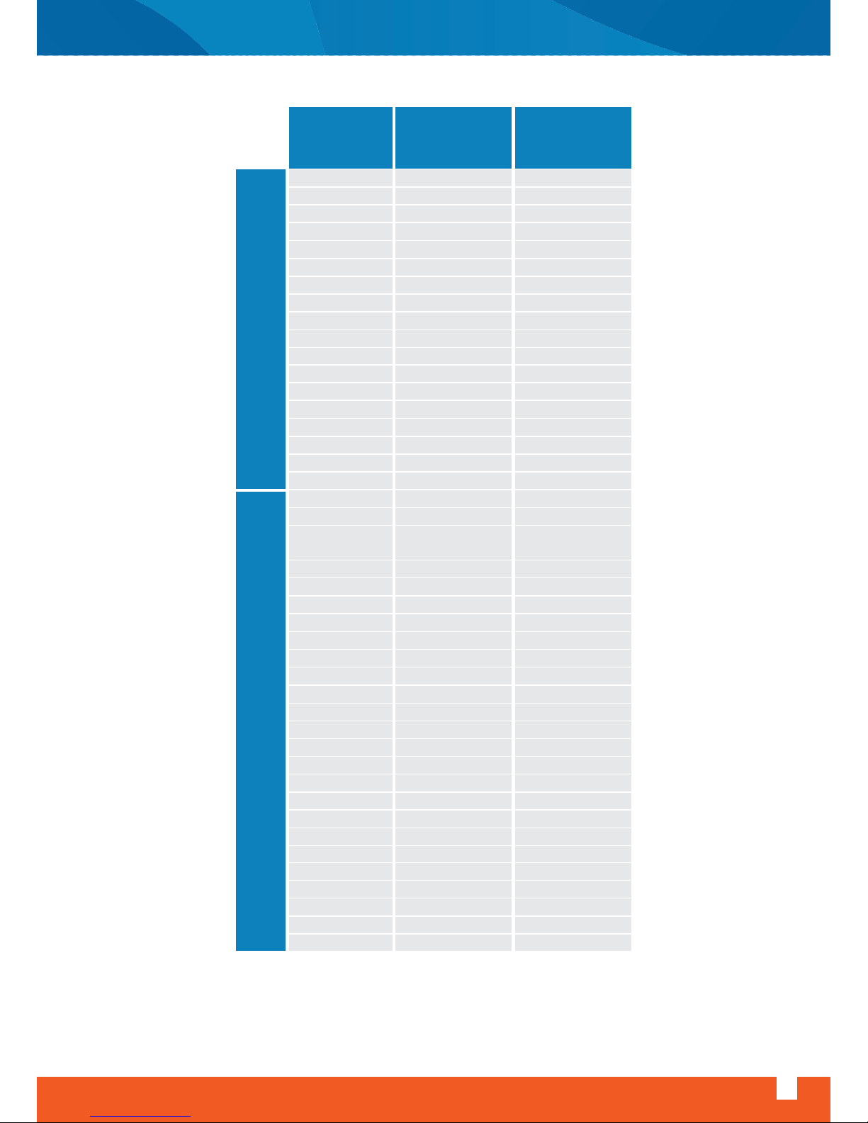
Air Handling Unit Installation, Operation And Maintenance Instructions
www.doguhvac.com
39
FAN TYPE
MAXIMUM
INSTALLED
POWER
kW
MAXIMUM
SPEED
rpm
TLZ 160
TLZ 180
TLZ 200
TLZ 225
TLZ 250
TLZ 280
TLZ 315
TLZ 355
TLZ 400
TLZ 450
TLZ 500
TLZ 560
TLZ 630
TLZ 710
TLZ 710T
TLZ 800T
TLZ 900T
TLZ 1000T
T-HLZ 180
T-HLZ 200
T-HLZ 225
T-HLZ 250
T-HLZ 280
T-HLZ 315
T-HLZ 355
T-HLZ 400
HLZ 400R
T-HLZ 450
HLZ 450R
T-HLZ 500
HLZ 500R
T-HLZ 560
HLZ 560T
T-HLZ 630
HLZ 630T
T-HLZ 710
T-HLZ 710T
HLZ 710T
T-HLZ 800T
HLZ 800T
T-HLZ 900T
HLZ 900T
T-HLZ 1000T
HLZ 1000T
3.5
3.5
4
5
5
6.3
7
9
9
11
11
13.5
13.5
14
22
25
32
40
3
3.5
4
5
5.2
5.6
7
7.5
14
8
20
10
20
14
35
12.5
40
12.5
18
45
18
45
30
70
35
70
4250
4000
3800
3400
3000
2730
2200
1900
1700
1500
1300
1200
1000
750
850
750
650
600
7000
6200
6200
5800
4700
3700
3400
2850
3600
2500
3400
2100
2800
2000
2800
1550
2300
1300
1500
2050
1200
1650
1200
1600
1065
1330
BACKWARD CURVED BLADE FANS, TYPE “RDH”BACKWARD CURVED BLADE FANS
Page 42

40
www.doguhvac.com
Air Handling Unit Installation, Operation And Maintenance Instructions
MAXIMUM
SPEED
rpm
MAXIMUM
INSTALLED
POWER
kW
MAXIMUM
SPEED
rpm
TZAF 355B
TZAF 355T1
TZAF 355T2
TZAF 400B
TZAF 400T1
TZAF 400T2
TZAF 450B
TZAF 450T1
TZAF 450T2
TZAF 500B
TZAF 500T1
TZAF 500T2
TZAF 560B
TZAF 560T1
TZAF 560T2
TZAF 630B
TZAF 630T1
TZAF 630T2
TZAF 710B
TZAF 710T1
TZAF 710T2
TZAF 800T1
TZAF 800T2
TZAF 900T1
TZAF 900T2
TZAF 1000T1
TZAF 1000T2
6.5
9
12
6.5
9
14
8.5
13
18.5
9.5
13
22
11
18.5
35
11
18.5
40
14
22
45
22
50
33
70
35
75
3000
3650
4000
2700
3200
3700
2400
2850
3300
2100
2300
2820
1950
2200
2650
1550
1700
2350
1370
1700
2100
1300
1800
1300
1600
1050
1400
BACKWARD CURVED BLADE FANS, TYPE “RDH”
Page 43

14- Motor Technical Information
Siemens Low-voltage Three Phase Squirrel-cage Motors
3000 rpm (2 pole)
400V, 3ph, 50 Hz, degree of protection IP55, class F insulation, 40 °C
Air Handling Unit Installation, Operation And Maintenance Instructions
www.doguhvac.com
41
TYPE
SPEED
rpm
CURRENT
A
EFFICIENCY
µ, %
POWER FACTOR
CosØ
OUTPUT POWER
KW HP
1LA7 060-2AA60
1LA7 063-2AA60
1LA7 070-2AA60
1LA7 073-2AA60
1LA7 080-2AA60
1LA7 083-2AA60
1LA7 090-2AA60
1LA7 096-2AA60
1LA7 106-2AA60
1LA7 113-2AA60
1LA7 130-2AA60
1LA7 131-2AA60
1LA7 163-2AA60
1LA7 164-2AA60
1LA7 166-2AA60
1LA5 183-2AA60
1LA5 206-2AA60
1LA5 207-2AA60
1LA5 223-2AA60
1LA6 253-2AB60
1LA6 280-2AC60
1LA6 283-2AC60
0.18
0.25
0.37
0.55
0.75
1.1
1.5
2.2
3
4
5.5
7.5
11
15
18.5
22
30
37
45
55
75
90
1/4
1/3
1/2
3/4
1
1.5
2
3
4
5.5
7.5
10
15
20
25
30
40
50
60
75
100
120
2820
2830
2740
2800
2855
2845
2860
2880
2890
2905
2925
2930
2940
2940
2940
2940
2945
2945
2960
2965
2975
2975
0.50
0.68
1.00
1.36
1.73
2.40
3.25
4.55
6,10
7,80
10,30
13,80
20,00
26,50
32,50
39,00
53.00
65.00
78.00
93.00
128.00
150.00
63
65
66
71
73
77
79
82
84
86
86.5
88
89,5
90
91
91,7
92,3
92.8
93,6
93.5
94.3
94.7
0.82
0.82
0.82
0.82
0.86
0.87
0.85
0.85
0.85
0.86
0.89
0.89
0.88
0.90
0.91
0.88
0.89
0.89
0,89
0.91
0.90
0.91
Page 44

42
www.doguhvac.com
Air Handling Unit Installation, Operation And Maintenance Instructions
1500 rpm (4 pole) 50 Hz
400V, 3ph, 50 Hz, degree of protection IP55, class F insulation, 40 °C
TYPE
SPEED
rpm
CURRENT
A
EFFICIENCY
µ, %
POWER FACTOR
CosØ
OUTPUT POWER
KW HP
1LA7 060-4AB60
1LA7 063-4AB60
1LA7 070-4AB60
1LA7 073-4AB60
1LA7 080-4AA60
1LA7 083-4AA60
1LA7 090-4AA60
1LA7 096-4AA60
1LA7 106-4AA60
1LA7 107-4AA60
1LA7 113-4AA60
1LA7 130-4AA60
1LA7 133-4AA60
1LA7 163-4AA60
1LA7 166-4AA60
1LA5 183-4AA60
1LA5 186-4AA60
1LA5 207-4AA60
1LA5 220-4AA60
1LA5 223-4AA60
1LA6 253-4AA60
1LA6 280-4AA60
1LA6 283-4AA60
0.12
0.18
0.25
0.37
0.55
0.75
1.1
1.5
2.2
3
4
5.5
7.5
11
15
18.5
22
30
37
45
55
75
90
1/6
1/4
1/3
1/2
3/4
1
1.5
2
3
4
5.5
7.5
10
15
20
25
30
40
50
60
75
100
120
1350
1350
1350
1370
1395
1395
1415
1420
1420
1420
1440
1455
1455
1460
1460
1460
1460
1465
1470
1470
1480
1485
1485
0.42
0.56
0.76
1.03
1.45
1,86
2.55
3.40
4.70
6.40
8.20
11.40
15.20
21.50
28.50
35.00
41.00
55.00
66.00
80.00
97.00
134.00
160.00
55
60
60
65
67
72
77
79
82
82
85
86
87
88.5
90
90.5
91,2
91.8
92.9
93.4
93.8
94.3
94.6
0.75
0.77
0.79
0.80
0.82
0.81
0.81
0.81
0.82
0.83
0.83
0.81
0.82
0.84
0.84
0.83
0.84
0.86
0.87
0.87
0.87
0.86
0.86
Page 45

Air Handling Unit Installation, Operation And Maintenance Instructions
www.doguhvac.com
43
1000 rpm (6 poles) 50 Hz
400V, 3ph, 50 Hz, degree of protection IP55, class F insulation, 40 °C
TYPE
SPEED
rpm
CURRENT
A
EFFICIENCY
µ, %
POWER FACTOR
CosØ
OUTPUT POWER
KW HP
1LA7 063-6AB60
1LA7 070-6AB60
1LA7 073-6AA60
1LA7 080-6AA60
1LA7 083-6AA60
1LA7 090-6AA60
1LA7 096-6AA60
1LA7 106-6AA60
1LA7 113-6AA60
1LA7 130-6AA60
1LA7 133-6AA60
1LA7 134-6AA60
1LA7 163-6AA60
1LA7 166-6AA60
1LA5 186-6AA60
1LA5 206-6AA60
1LA5 207-6AA60
1LA5 223-6AA60
1LA6 253-6AA60
1LA6 280-6AA60
1LA6 283-6AA60
1LA6 310-6AA60
1LA6- 313-6AA60
0.09
0.18
0.25
0.37
0.55
0.75
1.1
1.5
2.2
3
4
5.5
7.5
11
15
18.5
22
30
37
45
55
75
90
1/8
1/4
1/3
1/2
3/4
1
1.5
2
3
4
5.5
7.5
10
15
20
25
30
40
50
60
75
100
120
850
835
830
920
910
915
915
925
940
950
950
950
960
960
970
975
975
978
980
982
984
988
988
0.44
0.62
0.61
1.20
1.60
2.05
2.85
3.90
5.20
7.20
9.40
12.80
17.00
24.50
31.50
38.50
45,50
61.00
69.00
81.00
99.00
136.00
162.00
45
56
61
62
67
69
72
74
78
79
805
83
86
87.5
89.5
90.2
90.8
91.8
92.4
93.0
93.0
93.8
94.2
0.66
0.75
0.76
0.72
0.74
0.76
0.77
0.75
0.78
0.76
0.76
0.76
0.74
0.74
0.77
0.77
0.77
0.77
0.84
0.86
0.86
0.85
0.85
Page 46

44
www.doguhvac.com
Air Handling Unit Installation, Operation And Maintenance Instructions
STARTER SELECT TABLE FOR 1500 OR 3000 RPM, 380 V ASYNCHRON MOTORS WITH SQUIRREL CAGE IN ACCORDANCE WITH IEC 292 STANDARD
POWER POWERS SHORT-CIRCUIT PROTECTION NORMAL THERMAL OVER LOAD WIRING THERMAL RELAY OVERLOAD WIRING
KW HP COSø A BREAKER An g1 AC3 A mm2 1NO 1NC 1NC A mm2
0.06 1/12 0.39 0.23 0.4 0.5 2 9 0.16-0.25 1.5
0.09 1/8 0.44 0.31 0.4 1 2 9 0.25-0.40 1.5
0.12 1/6 0.47 0.38 0.4 1 2 9 0.25-0.40 1.5
0.18 1/4 0.49 0.55 0.63 1 2 9 0.40-0.63 1.5
0.25 1/3 0.48 0.79 1 2 4 9 0.63-1 1.5
0.37 1/2 0.54 1.03 1.6 2 4 9 1-1.6 1.5
0.55 3/4 0.52 1.6 1.6 2 4 9 1.6-2.5 1.5
0.75 1 0.56 2 2.5 4 6 9 1.6-2.5 1.5
1.1 1.5 0.64 2.6 4 6 10 9 2.5-4 1.5
1.5 2 0.65 3.5 4 6 10 9 2.5-4 1.5 9 9 9 1.5-2.5 1.5
2.2 3 0.66 5 6 8 16 9 4-6 1.5 9 9 9 2.5-4 1.5
3 4 0.69 6.6 8 12 20 9 5.5-8 1.5 9 9 9 2.5-4 1.5
3.7 5 0.73 7.7 8 12 20 9 5.5-8 2.5 9 9 9 4-6 1.5
4 5.5 0.71 8.5 10 12 20 9 7-10 2.5 9 9 9 4-6 1.5
5.5 7.5 0.73 11.5 13 16 25 12 10-13 4 9 9 9 5.5-8 2.5
7.5 10 0.73 15.5 15 20 32 16 13-18 6 12 12 9 7-10 4
11 15 0.75 22 25 25 50 25 18-25 10 12 12 9 10-13 6
15 20 0.75 30 50 40 63 32 23-32 16 16 16 9 13-18 10
18.5 25 0.75 37 50 40 80 40 30-40 25 16 16 9 18-25 16
22 30 0.75 44 50 63 100 50 38-50 25 32 32 16 23-32 25
30 40 0.75 60 100 63 100 63 57-66 35 50 50 25 30-40 25
37 50 0.78 72 100 80 125 80 63-80 50 50 50 25 38-50 35
45 60 0.8 85 100 80 125 145 75-105 50 50 50 40 48-57 50
55 75 0.79 105 125 100 160 145 95-125 70 50 50 40 57-66 50
75 100 0.82 138 160 160 250 145 100-160 95 80 80 50 63-80 70
90 125 0.8 170 250 200 315 185 125-200 120 145 145 80 75-105 95
110 150 0.81 205 250 250 400 265 200-315 120 145 145 80 100-160 95
132 180 0.81 245 250 315 500 265 200-315 185 185 145 100-160 120
136 220 0.81 300 500 315 500 400 250-400 185 185 145 125-200 120
200 270 0.82 370 500 500 800 400 315-500 265 265 185 200-315
220 300 0.81 408 500 500 800 500 315-500 265 265 185 200-315
250 340 0.82 460 500 500 800 500 400-630 400 400 265 200-315
315 430 0.81 584 630 800 630 400-630 400 400 265 250-400
335 450 0.82 620 630 800 630 500-800 500 500 265 250-400
400 545 0.85 710 800 1000 780 500-800 500 500 400 315-500
500 680 0.84 900 1000 1250 630-1000 630 630 400 400-630
FACTOR In CIRCUIT FUSE CONTACTOR RELAY ADJUC TRANGE CROSS SECTION LINE ∆ Y ADJUST RANGE CROSS SECTION
Page 47

15- Producing Company
DOĞU İKLİMLENDİRME SAN. VE TİC. A.Ş I.T.O.B. O.S.B 10010 Sok. No:4 35473 Tekeli Menderes IZMIR
TURKEY
Tel:+90 232 799 02 40
Fax:+90 232 799 02 44
AUTHORIZED SERVICES
ANKARA
GÜVEN TEKNİK
BEKİR YERLİKAYA
0.542.527.7878
ANTALYA
REFSER LTD ŞTİ
AHMET ÖZDERE
Sinan Mah. 1276 Sok. Palmiye Apt.No 4/2 Antalya
0.242.3120244
0.532.2128109
IZMIR
MERIDYEN HAVALANDIRMA
SABAHATTIN AKYAR
5854 Sk.No:6 Karabağlar/İZMİR
0.232.2651009
TABLE
GUARANTEE PERIOD :2 YEARS
PHYSICAL LIFE :10 YEARS
Air Handling Unit Installation, Operation And Maintenance Instructions
www.doguhvac.com
45
Page 48

DEVICE CODE DEVICE MODEL
KS-1
EA-1
KS-2
EA-2
KS-3
EA-3
KS-4
EA-4
HKS-5
EA-5
HKS-6
EA-6
HKS-7
EA-7
KKS-S 093-093
KKS-A 124-062
KKS-S 124-093
KKS-S 124-062
KKS-S 093-093
KKS-S 093-093
KKS-S 124-062
KKS-A 093-062
KKS-S 155-124
KKS-S 124-124
KKS-S 062-062
KKS-S 062-062
KKS-S 093-093
KKS-S 093-093
DEVICE CODE DEVICE MODEL
KS-12
EA-12
KS-13
EA-13
KS-14
EA-14
KS-15
EA-15
KS-16
EA-16
KS-17
EA-17
KS-18
EA-18
KKS-S 155-155
KKS-S 155-155
KKS-S 124-093
KKS-S 124-093
KKS-S 093-093
KKS-A 124-062
KKS-S 093-093
KKS-A 093-093
KKS-S 155-155
KKS-S 155-124
KKS-S 124-093
KKS-A 093-093
KKS-S 093-093
KKS-S 093-093
Warranty Certificate
Midyat Hospital Air Handling Units And Celled Aspirators
The FOUR SEASON brand air handling units and celled aspirators we manufacture which list is given below
are under our guarantee against defects in material and workmanship for two years from date of
consignment for given conditions below;
• The physical and technical faults which can occur due to failure to maintain devices good during storing
them in worksite are out of our warranty scope.
• Any transactions done to our devices without our service personnel will override our guarantee.
• The burning motor etc. faults which are caused by voltage surges and wrongly done electrical
installations are out of our warranty scope.
• The spare part and service guarantee is given by our firm to devices we manufacture for 10 years.
Best regards,
46
www.doguhvac.com
Air Handling Unit Installation, Operation And Maintenance Instructions
Stamp-signature-date Stamp-signature-date
Page 49
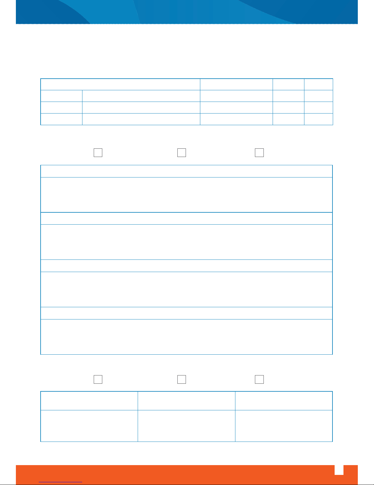
DELIVERY REPORT
Service / Delivery / Maintenance Form
Air Handling Unit Installation, Operation And Maintenance Instructions
www.doguhvac.com
47
FIRM
COMMISSIONING FAULT MAINTENANCE
FACILITY NAME
PHONE
NOTIFICATION DATE
DEPARTURE TO SERVICE DATE
SOLUTION DATE
..../..../201...
..../..../201...
..../..../201...
...... : ......
...... : ......
...... : ......
SERVICE SUPPLIED
VEHICLE LICENSE PLATE NUMBER SERVICE PERSONNEL RECIPIENT COMPANY REPRESENTATIVE
Service Type
Transaction Done In Service
DATE HOUR
IN WARRANTY OUT OF WARRANTY
SIGNATURE
DATE
SIGNATURE
DATE
OTHER
Warranty Condition
Description Of Solution
Customer Feedback (To Be Completed By Customer)
Suggestions For Improvements To Be Done (In-house)
Page 50

17- Decleration Of Conformity
DECLARATION OF CONFORMITY
We, DOĞU İKLİMLENDİRME SAN. VE TİC. A.Ş.. headquartered at 10010 Sk. No:4 İTOB Organize Sanayi
Bölgesi Tekeli Menderes - İZMİR – TURKEY hereby declares that the products KKS – S and KKS – H series
AIR HANDLING UNITS manufactured at 10010 Sk. No:4 İTOB Organize Sanayi Bölgesi Tekeli Menderes İZMİR – TURKEY (Tel: + 90 232 799 02 40, Fax:+ 90 232 799 02 44), with the brand name FOURSEASON
complies with the essential requirements of the directives;
- Machinery (MD) 98/37 EC,
- Low Voltage (LVD) 73/23 EEC,
and the standards applied in order to verify compliance with directives;
EN 60204-1:1997
EN 292-1/2:1991
EN 294:1992
Date of Issue: 26.04.2012
Name: Seçkin Tuncer ERDOĞMUŞ
Title: General Coordinator
Signature:
48
www.doguhvac.com
Air Handling Unit Installation, Operation And Maintenance Instructions
Page 51

Air Handling Unit Installation, Operation And Maintenance Instructions
www.doguhvac.com
49
NOTES
Page 52
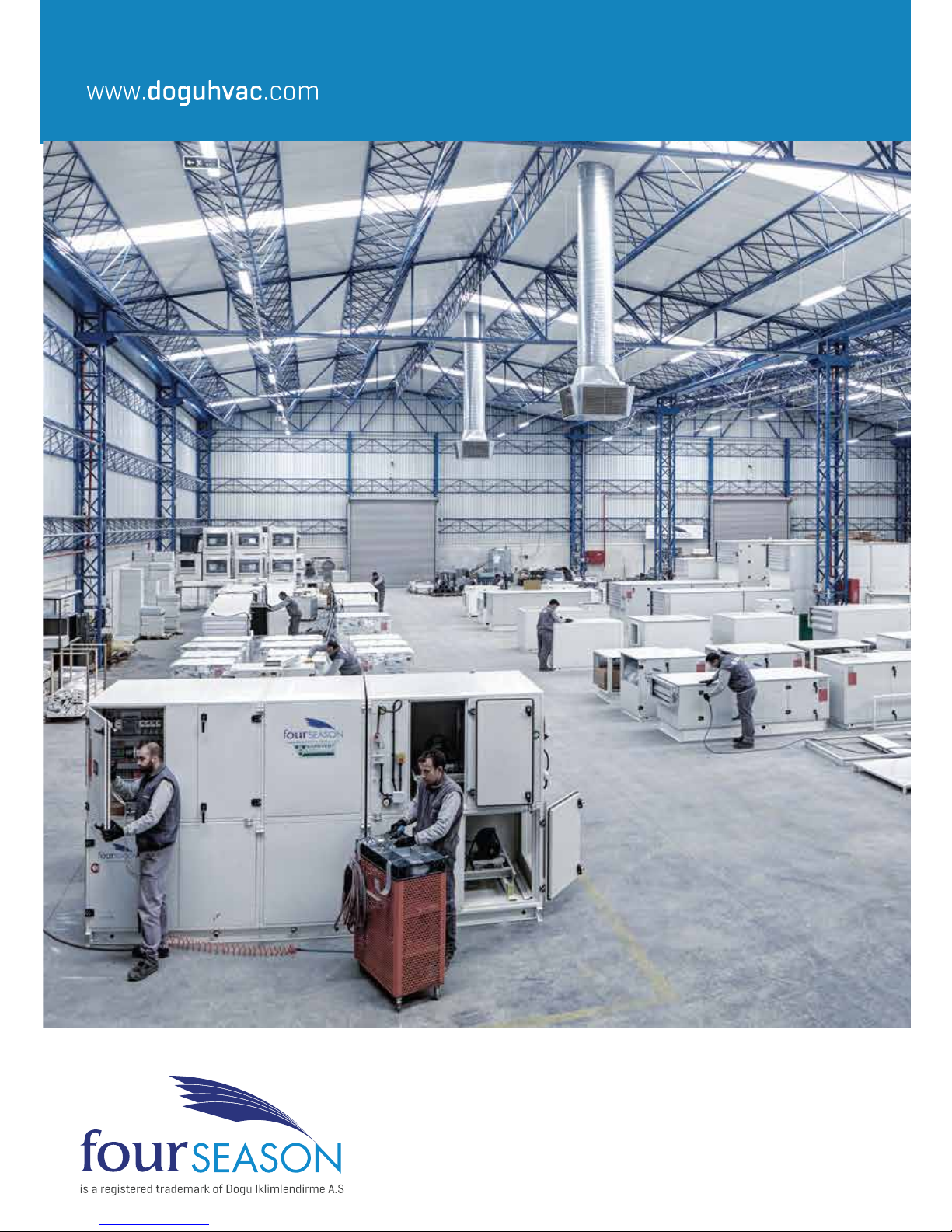
Page 53

Page 54

www.doguhvac.com
Factory
ITOB Organize Sanayi Bölgesi 10010 Sok.
No: 4 35477 Tekeli / Menderes / Izmir / TURKEY
Tel: +90 (232) 799 02 40 Faks: +90 (232) 799 92 04
Istanbul Area
Barbaros Mah. Çigdem Sok. No:1 Agaoglu My Office
Kat: 4/18 Atasehir/Istanbul / TURKEY
Tel: +90 (216) 250 55 45 Faks: +90 (216) 250 55 46
Ankara Area
Çetin Emeç Bulvarı 1065 Cad. (Eski 2.Cad) 1309 Sok.
No: B/4 Öveçler / Çankaya / ANKARA / TURKEY
Tel: +90 (312) 472 11 45 Faks: +90 (312) 472 11 46
09102015
 Loading...