

Dogtra eF-3000 User Manual

Copyright c 2004 Dogtra Company
FROM THE BUILDERS OF THE
WORLD’S FINEST E-COLLARS
OWNER’S MANUAL
2004
-
www.dogtra.com

3
CONTENTS
OVERVIEW
MAIN FEATURES
SAFETY FEATURES
PACKAGE CONTENTS
DESCRIPTION OF TRANSMITTER PARTS
DESCRIPTION OF COLLAR PARTS
CHARGING THE RECEIVER/COLLAR
TESTING YOUR
PRIOR TO INSTALLATION
INSTALLATION
TROUBLESHOOTING
MAINTENANCE
OPTIONAL ACCESSORIES
WARRANTY AND REPAIR
4
5
5
6
7
16
23
25
27
39
41
42
44

5
MAIN FEATURES
4
The gives you the
ability to allow your dog the freedom he wants, within
your specified boundaries. The invisible fencing system
contains your dog without the use of conventional fencing
that can be chewed through, jumped over or dug under.
The width of the signal field and the strength of the
electrical stimulation can be easily adjusted at the wallmount transmitter. In the “Stimulation Only” mode, your
dog will only receive the stimulation. In the
“Pager+Stimulation” mode, your dog will receive a silent
pager/vibration, followed by stimulation when he
approaches the boundary area. Once your dog consistently
avoids the signal boundary, the stainless steel contact
points can be replaced with the plastic training probes.
With the plastic training probes, your dog will be able to
respond to the vibration warning without receiving any
electrical stimulation.
Accessories for the Dogtra e-Fence system such as
additional wire, flags, lightning/surge protector, European
220-volt battery charger, and the 24-hour multi-contact
pad are available by calling Dogtra Company at 888-8119111 (PDT).
OVERVIEW
OVERVIEW
Waterproof collar/receiver
Pager/vibration signal that warns the dog prior to
electrical stimulation/correction
Wire continuity indicator shows the fence is
operational
Adjustable intensity for a variety of dog
personalities
Rechargeable receiver
Long-range signal(will work up to 40 acres)
User-friendly controls
MAIN FEATURES
Dogtra’s e-Fence system collars use state-of-theart microcomputer technology. The receiver has an
automatic control that limits the stimulus to eight
seconds.
Dogtra s filtering system prevents reception from
outside sources other than your transmitter.
SAFETY FEATURES
7
TRANSMITTER
DESCRIPTION OF
TRANSMITTER PARTS
6
Wall-Mount Transmitter
Collar/Receiver
Magnetic ON/OFF Switch Tool
Transmitter Adaptor (25-volt 500mA)
Receiver Adaptor (12-volt 300mA)
Test Lamp
Boundary Training Flags (50 ea)
18 ga Underground Fence Wire (500 feet)
Splices(4 ea)
Ground Wire(green)
Transmitter Mount Screws (2 ea)
Plastic Anchors(2 ea)
Plastic Training Probes
Longer Contact Points(2 ea)
Owner s Manual
Training Book
PACKAGE CONTENTS
PACKAGE CONTENTS
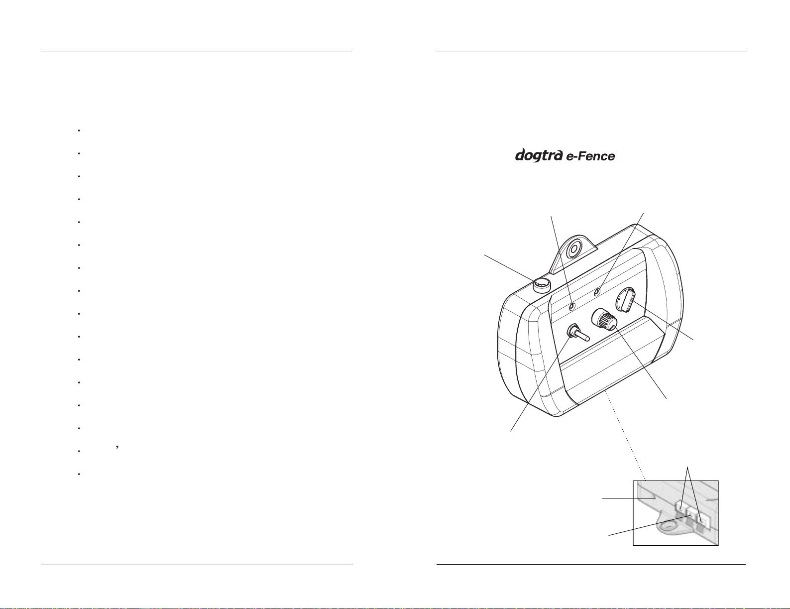
transmitter
Wire Indicator Light
ON/OFF Indicator Light
Magnetic ON/OFF
Switch Tool Holder
Adaptor Jack
Connector
Connector for Ground Wire
Wire Connectors for
Splicing
Field Width
Adjustment Knob
Intensity Selection
Dial
ON/OFF & Function
Selection Switch
9
TRANSMITTER
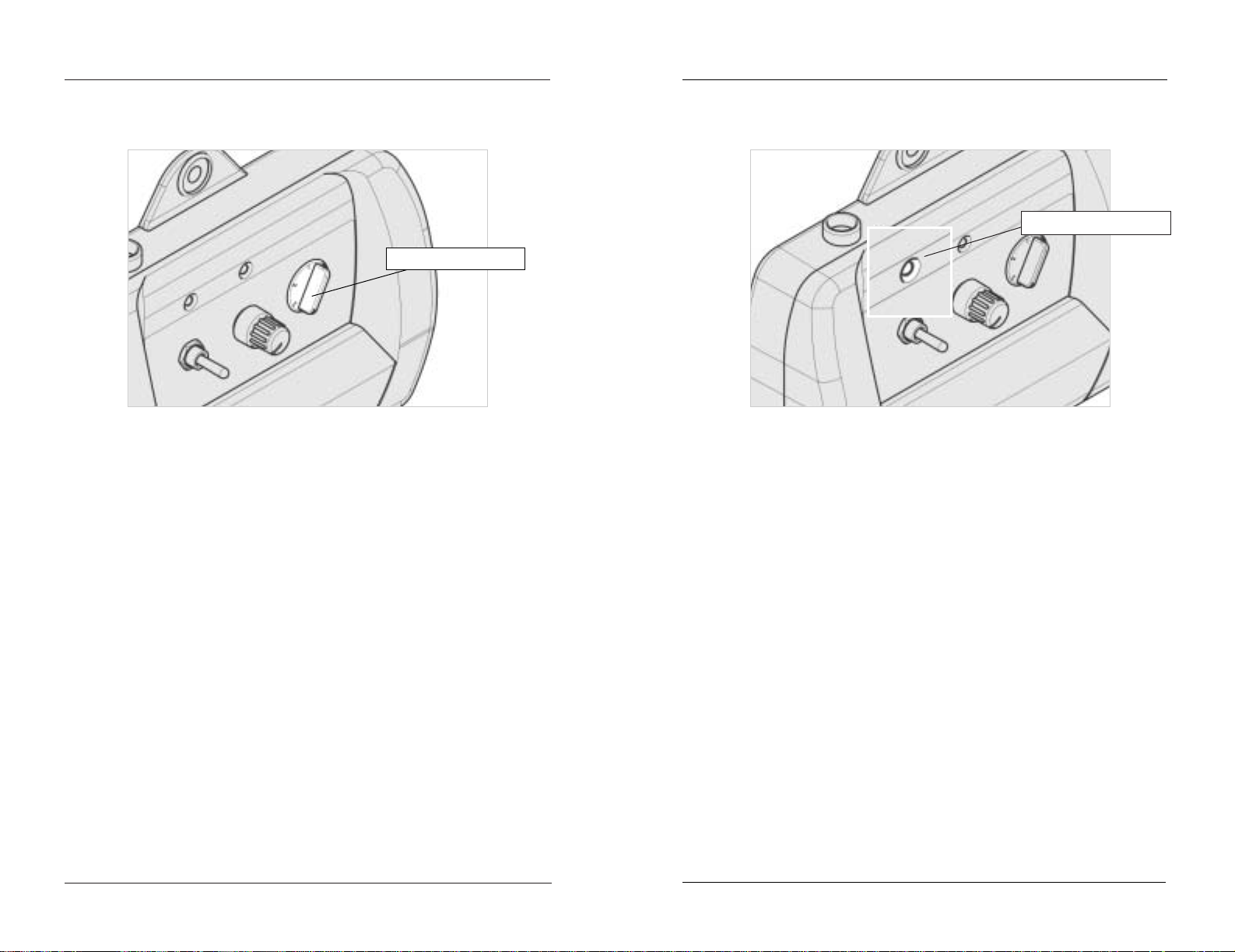
Field Width Adjustment Knob
This knob controls the width of the signal field
(the distance from the boundary wire to the location
where the collar/receiver first activates). Turning
the knob clockwise increases the field width, giving
your dog a wider area before the activation begins.
Turning it counter-clockwise decreases the signal
field, thus giving the dog a shorter area prior to
activation.
8
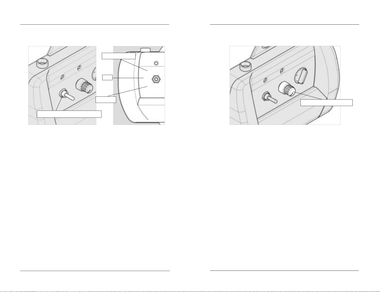
ON/OFF & Function Selection Switch
The ON/OFF Selection switch has three
functions. When the toggle switch is in the up
position, the unit will give the dog a pager/vibration
followed by stimulation correction. When the
toggle switch is in the down position, only
stimulation occurs (without the pager warning).
When the switch is in the middle position, the
power is off.
TRANSMITTER
Pager+Stim
OFF
Stimulation
Pager+Stimulation
ON/OFF & Function Selection Switch
OFF
Stimulation
Field Width Adjustment Knob
11
TRANSMITTER
ON/OFF Indicator Light
When the ON/OFF & Function Selection
switch is either in the up or down position, the
LED light will be on, indicating that the power is
on. When the switch is in the middle position, the
light goes off, indicating that the power is off.
10
Intensity Selection Dial
The Intensity Selection Dial controls the
stimulation level. Level 1 is the lowest setting and
level 5 is the highest. It is always best to start at
level 1 and increase one level at a time until you
find a level where the dog reacts to the stimulation
but does not overreact with excessive
vocalization.
TRANSMITTER
Intensity Selection Dial
ON/OFF Indicator Light
13
TRANSMITTER
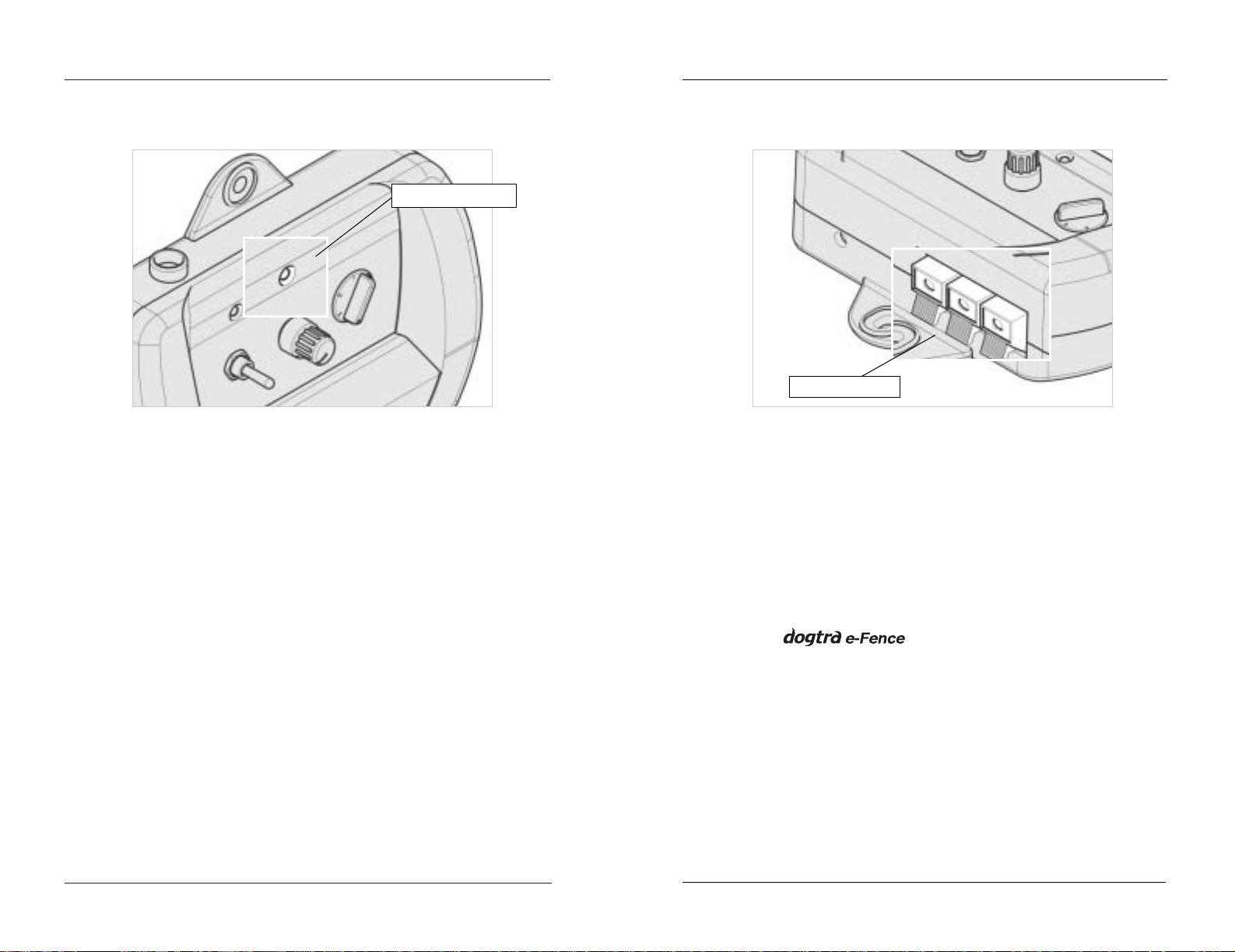
Wire Connectors For Splicing
The easy-to-use push-release wire connectors
let you instantly connect or disconnect the
boundary wire leads. Wires should be stripped
approximately a half-inch before being inserted
into the red connectors on the bottom of the wall
mount transmitter.
comes with a ground wire to
protect the unit in the event of lightning/power
surge. Strip about a half-inch on each end of the
ground wire and insert one end into the black
connector on the bottom of the wall transmitter.
The other end should be buried into the ground or
wrapped around a water pipe and secured with
electrical tape.
Option : A lightning/surge protector can be
purchased if there are no grounding options near
the wall transmitter.
12
Wire Indicator Light
When the wires are connected properly, the
wire indicator light will be on. In the event the
e-Fence wire becomes damaged, the light will
automatically turn off.
TRANSMITTER
Wire Indicator Light
Wire Connectors
15
TRANSMITTER
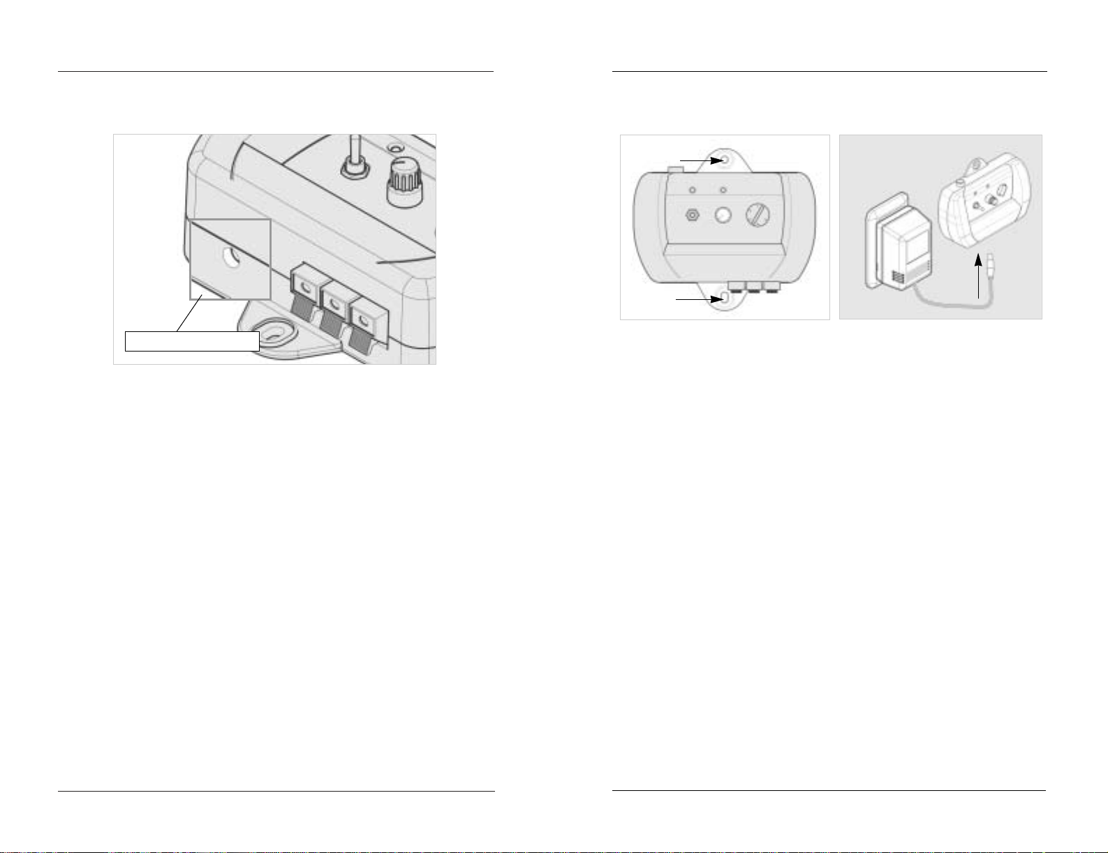
Wall-Mount Transmitter
Use the (2) included screws to mount the
transmitter to a wall, securely, near any standard 110volt household outlet. The unit will withstand
freezing temperatures, but it is not waterproof.
Therefore, we recommend mounting the transmitter
in a safe, dry sheltered area such as a shed, garage or
carport. Plastic anchors have been provided to secure
mounting onto drywall. Use a 1/4” drill bit to make
holes into the drywall. Insert the anchors into the
holes so that the open end faces out and mount the
transmitter by inserting the screws into the open end
of the anchors.
To power the wall transmitter, plug the AC
adaptor into the standard 110-volt outlet and connect
it to the adaptor jack connector of the transmitter.
14
Adaptor Jack Connector
Plug the 110-volt adaptor into a 110-volt wall
outlet and insert the adaptor plug into the adaptor
jack connector of the transmitter.
TRANSMITTER
110-volt
25V 500mA
Adaptor Jack Connector
 Loading...