

Page 1

Doepke
Dupline
Signalumsetzer DSU 2U
2-fach Binäreingabe für Gleich- und Wechselspannungen
DSU 2U Signal Converter
2-way Binary Input for AC / DC
Bedienungsanleitung
Operating Instructions
Inhaltsverzeichnis
1. Allgemeines.............................. 2
2. Kodierung................................. 2
3. Inbetriebnahme ........................ 2
4. Anzeigen .................................. 3
5. Technische Daten .................... 3
6. Garantie ................................... 4
13. Anschlussschema / Connection
Diagram.................................... 8
10. Indicators.................................. 6
11. Technical Data ......................... 6
12. Guarantee ................................7
13. Anschlussschema / Connection
3931196/04/08/E
Table of Contents
7. General Information ................. 5
8. Coding...................................... 5
9. Putting into Service .................. 5
Diagram.................................... 8
Page 2

Doepke
Bedienungsanleitung
Dupline Signalumsetzer DSU 2U
1. Allgemeines
Der Signalumsetzer DSU 2U ist eine Komponente des Dupline Installationssystems und
ermöglicht die Umsetzung von zwei Spannungssignalen zur Übertragung auf dem Dupline-Bus.
Die Eingänge sind für Gleichspannungen von 20 V bis 300 V oder Wechselspannungen
von 20 V bis 250 V bei 50 Hz geeignet; auf Polarität muss nicht geachtet werden. Zudem
ist ein gemischter Betrieb zulässig.
Bei fachgerechter Montage und Nutzung einer Spannungsart für alle Kanäle erfüllt der
DSU 2U die Bestimmungen für Schutzkleinspannung zwischen Netz- und Steuerseite.
Die Betriebsversorgung erfolgt aus dem Dupline-Bus, wodurch der Einbau dezentral,
z.B. in Schalterdosen oder Hohlräumen, erfolgen kann.
Die frontseitig angebrachte, grüne LED zeigt die ordnungsgemäße Arbeitsweise des Dupline Busses an.
2. Kodierung
Mit dem Handkodiergerät DHK 1 kann über den Flachsteckeranschluss an der Front des
DSU 2U jedem Eingangskanal jede beliebige Adresse zwischen A1 und P8 zugeordnet
werden. Die Kanalzuordnung ist wie folgt:
Kanal Beschreibung Kanal Beschreibung
1 Eingangssignal E1 5 Nicht belegt
2 Eingangssignal E2 6 Nicht belegt
3 Nicht belegt 7 Nicht belegt
4 Nicht belegt 8 Nicht belegt
Funktionen, die nicht benötigt werden, sollten unkodiert bleiben. Die Kodierung des
DSU 2U kann ohne Versorgungsspannung sowie ohne Dupline-Signal vorgenommen
werden. Sie bleibt dauerhaft erhalten, kann aber jederzeit überschrieben werden.
3. Inbetriebnahme
Die Installation darf nur von einer autorisierten Fachkraft vorgenommen werden. Bei der
Installation ist das Anschlussschema zu beachten. Alle anzuschließenden Leitungen
müssen spannungsfrei sein. Verbindungen zwischen dem Dupline-Signal und dem Erdpotenzial führen zu Störungen und sind nicht zulässig. Auf die richtige Polarität des Dupline-Signals ist zu achten.
Um Störungen zu vermeiden, sollte die Länge der eingangsseitigen Leitungen bei Wechselspannung 50 m und bei Gleichspannung 100 m nicht überschreiten. Durch die interne
Gleichrichtung der Eingangssignale ist es auch bei Gleichspannung nicht notwendig, auf
die Polarität zu achten.
Die Anschlussklemmleiste verfügt über doppelt ausgeführte Dupline-Signalleiteranschlüsse. Diese sind untereinander verbunden und können zum Durchschleifen des Dupline-Signals genutzt werden.
2 3931196/04/08/E
Page 3

Doepke
Folgende Tabelle zeigt die Anschlussbelegung:
Klemme Beschreibung Klemme Beschreibung
D+ Dupline Signalleiter + (Dupline+) Schwarz Eingangssignal 1 (E1)
D+ Dupline Signalleiter + (Dupline+) Schwarz Eingangssignal 1 (E1)
D- Dupline Signalleiter - (Dupline-) Braun Eingangssignal 2 (E2)
D- Dupline Signalleiter - (Dupline-) Braun Eingangssignal 2 (E2)
NC Nicht verwendet
Um den Forderungen für Schutzkleinspannung zu genügen, ist bei der Installation die
VDE0100, Teil 410 zu beachten und anzuwenden. Bei einem Mischbetrieb von Gleichund Wechselspannungen werden die Bedingungen jedoch nicht
4. Anzeigen
Anzeige Beschreibung
Grüne „BUS OK“LED
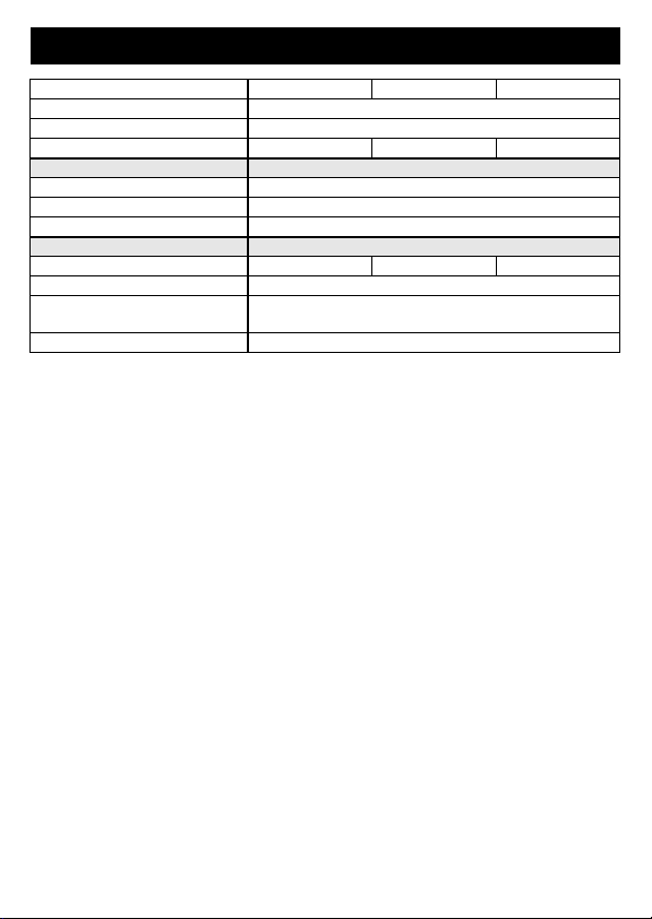
5. Technische Daten
Dupline
Eingänge
Gleichspannung
Wechselspannung (50 Hz)
Betriebsspannung
Nennbetriebsspannung nicht erforderlich (aus Dupline-Signalleiter)
Anschlüsse
Steueranschlüsse
Dupline-Bus:
Aus: Busstörung / An: Bus OK
Min. Typ. Max.
Stromaufnahme 500 µA
Eingangskanäle 2 Eingangssignale (E1/E2)
Ausgangskanäle Keine
Art optoentkoppelt, mit Gleichrichtung
Nennspannung 20 V 300 V
Stromaufnahme 100 µA
Leitungslänge 100 m
Nennspannung 20 V 250 V
Stromaufnahme 15 mA
Leitungslänge 50 m
Art 2-polige Steckklemmen (montiert)
Klemmbereich 0,4 mm ∅ 0,8 mm²
erfüllt.
3931196/04/08/E 3
Page 4
Doepke
Netzanschlüsse
Gehäuse
Allg. technische Daten
Bestellnummer, -bezeichnung 09 501 136, Signalumsetzer DSU 2U
6. Garantie
Für fachgerecht montierte, unveränderte Geräte gewähren wir ab Kauf durch den Endverbraucher die gesetzliche Gewährleistungsfrist. Die Garantie bezieht sich nicht auf
Transportschäden sowie Schäden, die durch Kurzschluss oder Überlastung entstanden
sind. Bei Fertigungs- und Materialfehlern, die innerhalb der Gewährleistungsfrist erkannt
werden, leistet unser Werk kostenlosen Ersatz. Bei Öffnen des Gerätes erlischt der Garantieanspruch.
Klemmbereich 0,75 mm²
Betriebstemperatur -10°C +35°C
Luftfeuchtigkeit max. 85% (Betauung nicht zulässig)
Schutzart / Normen IEC60669, EN55022 / EN50081-1 und EN55024 /
Art 4 Leitungen LiY mit Aderendhülsen
Art Laschengehäuse
Maße 42 x 42 x 34 (B x H x T in mm)
Material Polyamid PA6
Min. Typ. Max.
EN50082-1
4 3931196/04/08/E
Page 5

Doepke
Operating Instructions
Dupline DSU 2U Signal Converter
7. General Information
The DSU 2U signal converter is a component of the Dupline installation system and is
able to convert two voltage signals for transmission on the Dupline bus.
The inputs are each suitable for DC voltage from 20 V to 300 V or AC voltages from 20 V
to 250 V at 50 Hz. They can be operated simultaneously. There is no need to observe a
specific polarity.
With proper installation, and using only one type of voltage for both channels, the device
complies with the regulations for protective low voltage between mains and control circuit.
As it is supplied by the Dupline bus, it can be fitted in a convenient local position, e.g. in
switch socket boxes or cavities.
The green LED on the front indicates the proper functioning of the Dupline bus.
8. Coding
With the DHK 1 hand encoder each channel can be assigned any address between A1
and P8 via the flat-plug connector on the front of the DSU 2U. The allocation of the channels is as follows:
Channel Description Channel Description
1 Input Signal 1 5 Not assigned
2 Input Signal 2 6 Not assigned
3 Not assigned 7 Not assigned
4 Not assigned 8 Not assigned
Functions which are not required should remain uncoded. Encoding the DSU 2U requires neither a power supply nor the Dupline signal. Although the coding is permanently
retained, it may always be overwritten.
9. Putting into Service
Installation may only be carried out by an authorized technician. Observe the connection
diagram when installing. All leads to be connected must be dead.
In order to avoid malfunctions, the length of leads at the input side should not exceed
50 m with AC voltage, and 100 m with DC voltage.
Because of rectification at the input side, there is no need to check for correct polarity.
The terminal board is provided with double connection points for the Dupline signal conductors. These are interconnected and can be used for through-looping of the Dupline
signal.
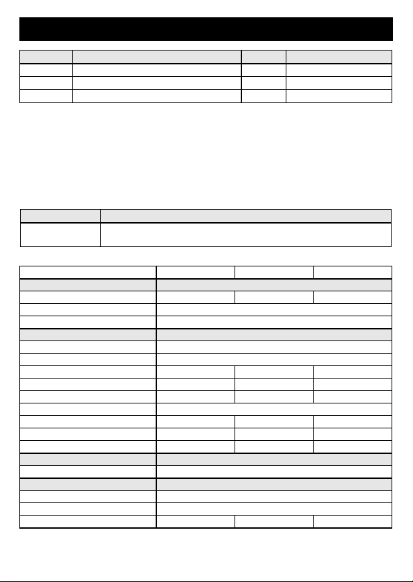
The following table illustrates the connection configuration:
Ter min al Description Ter min al Description
D+ Dupline signal conductor + (Dupline+) Black Input Signal 1 (E1)
D+ Dupline signal conductor + (Dupline+) Black Input Signal 1 (E1)
3931196/04/08/E 5
Page 6
Doepke
Ter min al Description Ter min al Description
D- Dupline signal conductor - (Dupline-) Brown Input Signal 2 (E2)
D- Dupline signal conductor - (Dupline-) Brown Input Signal 2 (E2)
NC Spare
Connections between the Dupline signal and earth potential will cause malfunctions and
are not permissible. In addition, check for the correct polarity of the Dupline signal.
In order to meet the requirements for protective low voltage, VDE0100, Part 410, should
be observed and put into practice during installation. For reasons of safety and space
requirements, mains cables may not be routed through the same installation box.
In cases of mixed operation with AC voltage at one input and DC voltage at the other,
the above requirements are not fulfilled.
10. Indicators
Indicator Description
Green “BUS OK”
LED
11. Technical Data
Dupline
Inputs
DC voltage
AC voltage (50 Hz)
Operating Voltage
Rated operating voltage Not required (supplied by Dupline signal line)
Ter min al s
Control terminals
Dupline bus:
Off - bus fault / On - bus OK
Min. Typ. Max.
Current input 500 µA
Input channels 2 input signals (E1/E2)
Output channels None
Type opto-decoupled, with rectification
Voltage 20V 300V
Current input 100 µA
Line length 100 m
Voltage 20V 250V
Current input 15 mA
Line length 50 m
Type 2-pole plug terminals (fitted)
Contact area 0.4 mm ∅ 0.8 mm²
6 3931196/04/08/E
Page 7

Doepke
Mains terminals
Housing
General technical data
Ambient temperature -10°C +35°C
Encl. protection type /
Order number, description 09 501 136, Signal converter DSU 2U
12. Guarantee
All professionally installed, unaltered devices are covered by warranty during the statutory guarantee period from the day of purchase by the end user. The guarantee is not
applicable to damage incurred during transport or caused by short-circuit or overloading.
In the event of defects in workmanship or material, which are discovered within the guarantee period, the company will provide a replacement free of charge. The guarantee will
be rendered null and void if the device is opened or tampered with.
Type 4 leads LiY with wire end ferrules
Contact area 0.75 mm²
Type Strap-type enclosure
Dimensions 42 x 42 x 34 (W x H x D in mm)
Material Polyamide PA6
Atm. humidity max. 85% (exposure to dew not permissible)
standards
Min. Typ. Max.
IEC60669, EN55022 / EN50081-1 and EN55024 /
EN50082-1
3931196/04/08/E 7
Page 8

Doepke
13. Anschlussschema / Connection Diagram
Sollten Sie Fragen zu diesem Produkt
oder zum Dupline-System haben, wenden Sie sich bitte an:
In case of queries concerning this
product or the Dupline system please contact:
Doepke
Schaltgeräte GmbH & Co. KG
Stellmacherstraße 11
D-26506 Norden, Germany
Tel.: +49 (0) 4931/1806-0
Fax: +49 (0) 4931/1806-101
8 3931196/04/08/E
Internet:
E-mail:
info@doepke.de
http://www.doepke.de
3931196/04/08/E
 Loading...