


3931178/02/05/D
Doepke
Dupline
Ein-/Ausgabeplatinen DNP 4 und DPN 4
Input/Output Boards DNP 4 and DPN 4
Bedienungsanleitung
Operating Instructions

2 3931178/02/05/D
Doepke
Inhaltsverzeichnis
1. Allgemeines ........................................................................................... 3
2. Kodierung .............................................................................................. 3
3. Inbetriebnahme...................................................................................... 3
4. Anzeigen................................................................................................ 4
5. Technische Daten.................................................................................. 4
6. Anschlussschema.................................................................................. 5
7. Garantie................................................................................................. 5
Table of Contents
8. General Information............................................................................... 6
9. Coding ................................................................................................... 6
10. Putting into Service................................................................................ 6
11. Indicators ............................................................................................... 7
12. Technical Data....................................................................................... 7
13. Connection Diagram.............................................................................. 8
14. Guarantee.............................................................................................. 8
Sollten Sie Fragen zu diesem Produkt
oder zum Dupline-System haben, wenden Sie sich bitte an:
In case of queries concerning this
product or the Dupline system please contact:
Doepke
Schaltgeräte GmbH & Co. KG
Stellmacherstraße 11
D-26506 Norden, Germany
Tel.: +49 (0) 4931/1806-0
Fax: +49 (0) 4931/1806-101
E-mail:
Internet:
info@doepke.de
http://www.doepke.de
3931178/02/05/D

3931178/02/05/D 3
Doepke
Bedienungsanleitung
Dupline Ein-/Ausgabeplatinen DNP 4 und DPN 4
1. Allgemeines
Die Ein- und Ausgabeplatinen DNP 4 und DPN 4 sind Komponenten des Dupline Installationssystems und ermöglichen die Eingabe von vier Schaltsignalen und das Schalten
von vier Verbrauchern über den Dupline-Bus. Die Ausgänge erlauben den Anschluss
von Kleinverbrauchern mit einer Spannung von 24 VDC und einem maximalen Strom
von 50 mA. Beim DNP 4 müssen diese Verbraucher mit einer Gleichspannung von 24 V,
beim DPN 4 mit dem Nullpotenzial versorgt werden.
Als Ausgangsstufen befinden sich NPN-Transistoren (DNP 4) oder PNP-Transistoren
(DPN 4) auf der Leiterplatte, deren offene Kollektoren auf Schraubklemmen geführt sind.
2. Kodierung
Mit dem Handkodiergerät DHK 1 kann über die Western-Modularbuchse auf der Leiterplatte jedem Kanal 1..8 jede beliebige Adresse zwischen A1 und P8 zugeordnet werden.
Die Kanalzuordnung ist wie folgt:
Nicht benötigte Kanäle sollten unkodiert bleiben. Die Kodierung der Platinen kann ohne
Versorgungsspannung sowie ohne Dupline-Signal vorgenommen werden. Sie bleibt
dauerhaft erhalten, kann aber jederzeit überschrieben werden.
Der Zustand der Ausgänge beim Auftreten eines Systemfehlers, wie z.B. bei Ausfall des
Bussignals, kann mit dem Handkodierer DHK 1 im Voraus festgelegt werden. Standardmäßig ist “Aus” eingestellt.
3. Inbetriebnahme
Die Installation darf nur von einer autorisierten Fachkraft vorgenommen werden. Da es
sich bei den Platinen um offene Leiterplatten handelt, ist bei der Montage und Installation
besondere Vorsicht geboten. Der Einbau der Leiterplatten muss so erfolgen, dass weder
Feuchtigkeit noch andere Umgebungseinflüsse die Funktion der Geräte beeinträchtigen
können. Auf ausreichende Isolation bzw. ausreichenden Abstand zu anderen spannungsführenden Leitungen und Teilen ist zu achten. Die beiliegenden Abstandshalter
sollten verwendet werden.
Die Platinen werden mit einer Versorgungsspannung von 24 VDC an den Klemmen
POW (24 VDC) und BUS- (0 V) betrieben. Um Potenzialunterschiede zu vermeiden,
muss die 0 V-Leitung der Spannungsversorgung direkt
zusammen mit dem Dupli-
ne Signalleiter (-) auf die „BUS-“-Klemme gelegt werden. Es darf zwischen beiden
Leitungen an keiner anderen Stelle zu Verbindungen kommen. Die Eingangssignale
(Kontakte oder Schalter) an den Klemmen I1..I4 sind gegen das 0 V-Potenzial der Spannungsversorgung zu schalten; sie düfen nicht direkt mit den Dupline Signalleiter (Dupli-
Kanal Beschreibung Kanal Beschreibung
1 Eingang 1 5 Ausgang 1
2 Eingang 2 6 Ausgang 2
3 Eingang 3 7 Ausgang 3
4 Eingang 4 8 Ausgang 4

4 3931178/02/05/D
Doepke
ne-) verbunden werden. Die Verbraucher an den Klemmen O1..O4 können beim DNP 4
durch gemeinsame Führung auf die Klemme DC+ mit der internen 24V-Spannung versorgt werden. Das Dupline-Signal muss auf die Klemmen BUS+ (Dupline+) und BUS(Dupline-) geführt werden. Das Dupline-Signal darf an keiner Stelle des Systems eine
Verbindung zum Erdpotenzial haben. Folgende Tabelle zeigt die Anschlussbelegung:
4. Anzeigen
5. Technische Daten
Klemme Beschreibung Klemme Beschreibung
I1 Eingang 1 O1 Ausgang 1
I2 Eingang 2 O2 Ausgang 2
I3 Eingang 3 O3 Ausgang 3
I4 Eingang 4 O4 Ausgang 4
BUS+ Dupline Signalleiter +
(Dupline+)
BUS- Dupline Signalleiter - (Dupline-) und
Betriebsspannung 0 VDC
POW +24 VDC Betriebsspannung DC+ Spannung für Ausgangslast (nur
DNP 4)
Anzeige Beschreibung
Gelbe LED Dupline-Bus: Aus: Busstörung / An: Bus OK
Grüne LED Betriebsspannung: Aus: nicht vorhanden / An: Betriebsspannung OK
Min. Typ. Max.
Dupline
Stromaufnahme 100 µA
Eingangskanäle 4 (Kanäle 1..4)
Ausgangskanäle 4 (Kanäle 5..8)
Eingänge
Art 4 Kontakte (über NPN-Transistoren)
Leerlaufspannung 8,0 V
Kontaktbelastung 180 µA
Einschaltspitzenstrom 7 mA
Übergangswiderstand 100 Ohm
Leitungslänge 3 m
Ausgänge DNP 4/DPN 4
Art NPN-/PNP-Transistoren, nicht kurzschlussfest
Spannungsabfall - / -2,0 V 1,2 V / -2,8 V
Schaltleistung 200 mA
Nennstrom (pro Ausgang) 50 mA
Leckstrom im Aus-Zustand 100 µA / 200 µA

3931178/02/05/D 5
Doepke
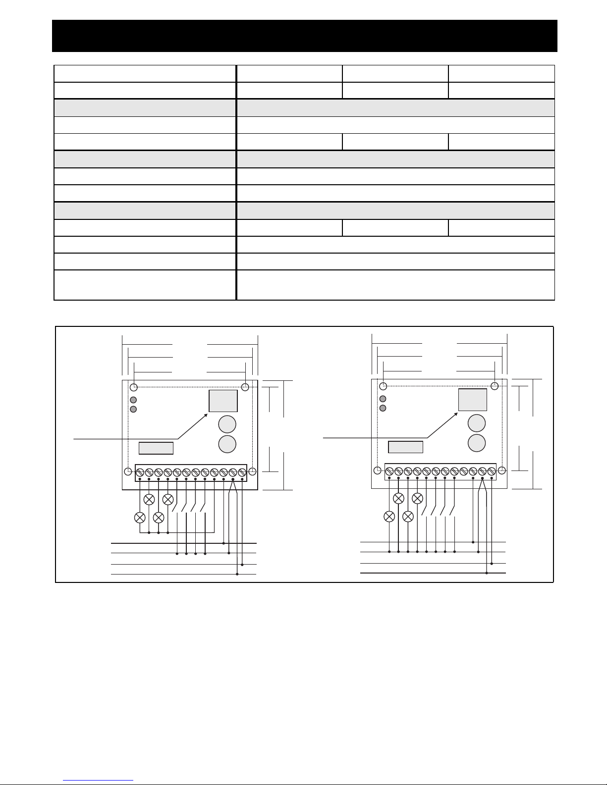
6. Anschlussschema
7. Garantie
Für fachgerecht montierte, unveränderte Geräte gewähren wir ab Kauf durch den Endverbraucher die gesetzliche Gewährleistungsfrist. Die Garantie bezieht sich nicht auf
Transportschäden sowie Schäden, die durch Kurzschluss oder Überlastung entstanden
sind. Bei Fertigungs- und Materialfehlern, die innerhalb der Gewährleistungsfrist erkannt
werden, leistet unser Werk kostenlosen Ersatz.
Betriebsspannung
Nennbetriebsspannung 10 VDC 24 VDC 30 VDC
Stromaufnahme 45 mA
Einschaltstrom 1 A
Anschlüsse
Art Schraubklemmen
Klemmbereich 0,4 mm ∅ 2,5 mm²
Gehäuse
Art Offene Leiterplatte
Maße 73 x 59 (B x H in mm)
Allg. technische Daten
Betriebstemperatur -20°C +50°C
Luftfeuchtigkeit 20%..80% (Betauung nicht zulässig)
Schutzart / Normen keine
Bestellnummer, -bezeichnung 09 501 131, 4-fach Ein-/Ausgabeplatine DNP 4
09 501 132, 4-fach Ein-/Ausgabeplatine DPN 4
Min. Typ. Max.
Dupline
Dupline -
Dupline +
0V DC
+24V DC
Betriebsspannung
Dupline-Bussignal
Buchse für
Kanalprogrammierung
DPN 4
60,0 mm
45,6 mm
59,0 mm
67,0 mm
73,0 mm
G2140 5520
3931179C
O4
O3 O2 O1 I4 I3 I2 I1
DC+
POW
BUS-
BUS+
Dupline
O4 O3 O2 O1
I4I3I2 I1
Dupline -
Dupline +
0V DC
+24V DC
Betriebsspannung
Dupline-Bussignal
Buchse für
Kanalprogrammierung
DNP 4
60,0 mm
45,6 mm
59,0 mm
67,0 mm
73,0 mm
G2140 5510
3931178C
DC+
POW
BUS-
BUS+

6 3931178/02/05/D
Doepke
Operating Instructions
Dupline Input/Output Boards DNP 4 and DPN 4
8. General Information
The DNP 4 and DPN 4 input and output boards are components of the Dupline installation system and permit four switch signals to be input and four loads to be switched via
the Dupline bus. Loads with a voltage of 24 VDC and a maximum current of 50 mA can
be connected to the outputs. Those loads have to be supplied with a DC voltage of 24 V
at the DNP 4 and with the ground potential at the DPN 4.
The output circuitry of the board is equipped with NPN-transistors (DNP 4) or PNP-transistors (DPN 4) whose open collectors are routed to screw terminals.
9. Coding
With the DHK 1 hand encoder each channel can be assigned any address between A1
and P8 via the Western modular socket on the circuit board. The allocation of the channels is as follows:
Channels which are not required should remain uncoded. Encoding the boards requires
neither a supply voltage nor the Dupline signal. Although the coding is permanently retained, it may always be overwritten.
As a safeguard in the event of a bus fault, the status of the outputs can be preset in advance with the DHK 1 hand encoder. The standard setting is "Off".
10. Putting into Service
Installation may only be carried out by an authorized technician. As the circuit boards are
not enclosed, particular care should be taken when mounting and installing them. They
must be installed so that neither moisture nor any other environmental conditions can affect their function. Attention should be paid that sufficient insulation is provided, as well
as enough distance from other live leads and parts. The enclosed spacers should be
used.
The circuit boards have to be operated with 24 VDC at terminals POW (24 VDC) and
BUS- (0 V). In order to avoid differences in potential, the common (O V) wire of the
voltage supply must be directly
connected together with the Dupline signal con-
ductor (Dupline-) to the „BUS-“ terminal. At no other point is a connection between
the two leads permissible. The input signals (contacts or switches) at terminals I1..I4
should be operated against the OV potential of the supply voltage; they may not be connected directly to the Dupline signal conductor (Dupline-). At the DNP 4, the loads at terminals O1..O4 can be supplied by the internal 24 V voltage by being jointly routed to the
DC+ terminal.
The Dupline signal must be routed to terminals BUS+ (Dupline+) and BUS- (Dupline-). At
Channel Description Channel Description
1 Input 1 5 Output 1
2 Input 2 6 Output 2
3 Input 3 7 Output 3
4 Input 4 8 Output 4

3931178/02/05/D 7
Doepke
no point within the system may the Dupline signal have a connection to earth potential.
The following table illustrates the connection configuration:
11. Indicators
12. Technical Data
Terminal Description Termina l Description
I1 Input 1 O1 Output 1
I2 Input 2 O2 Output 2
I3 Input 3 O3 Output 3
I4 Input 4 O4 Output 4
BUS+ Dupline signal conductor +
(Dupline+)
BUS- Dupline signal conductor -
(Dupline-) and 0 VDC operating
voltage
POW +24 VDC operating voltage DC+ Voltage for output load (DNP 4
only)
Indicator Description
Yellow LED Dupline bus: Off: bus fault / On: bus OK
Green LED Operating voltage: Off: no supply / On: operating voltage OK
Min. Typ. Max.
Dupline
Current input 100 µA
Input channels 4 (channels 1..4)
Output channels 4 (channels 5..8)
Inputs
Type 4 contacts (via NPN-transistors)
No-load voltage 8.0 VDC
Contact load 180 µA
Peak current at make 7 mA
Transisition resistance 100 Ohm
Length of line 3 m
Outputs DNP 4 / DPN 4
Type NPN-/PNP-transistors, not short-circuit-proof
Voltage drop - / -2.0 V 1.2 V / -2.8 V
Breaking capacity 200 mA
Rated current (per channel) 50 mA
Leakage current in Off-status 100 µA / 200 µA
Operating voltage
Rated operating voltage 10 VDC 24 VDC 30 VDC
Current input 45 mA
8 3931178/02/05/D
Doepke
13. Connection Diagram
14. Guarantee
All professionally installed, unaltered devices are covered by warranty during the statutory guarantee period from the day of purchase by the end user. The guarantee is not applicable to damage incurred during transport or caused by short-circuit or overloading. In
the event of defects in workmanship or material, which are discovered within the guarantee period, the company will provide a replacement free of charge.
Current at make 1 A
Termi nals
Type Screw terminal
Contact area 0.4 mm ∅ 2.5 mm²
Housing
Type Open printed circuit board
Dimensions 73 x 59 (W x H in mm)
General Technical Data
Operating temperature -20°C +50°C
Atm. humidity 20%..80% (exposure to dew not permissible)
Encl. prot. type / standards none
Order number, description 09 501 131, 4-way input/output DNP 4
09 501 132, 4-way input/output DPN 4
Min. Typ. Max.
Dupline
O4
O3 O2 O1 I4 I3 I2 I1
Dupline -
Dupline +
0V DC
+24V DC
DNP 4
60.0 mm
45.6 mm
59.0 mm
67.0 mm
73.0 mm
G2140 5510
Power supply
Dupline bus signal
Connector for
channel encoder
3931178EC
DC+
POW
BUS-
BUS+
Dupline
Dupline -
Dupline +
0V DC
+24V DC
DPN 4
45.6 mm
59.0 mm
G2140 5520
Power supply
Dupline bus signal
Connector for
channel encoder
3931179EC
O4
O3 O2 O1 I4 I3 I2 I1
DC+
POW
BUS-
BUS+
60.0 mm
67.0 mm
73.0 mm
 Loading...