

Page 1

doepfer
Leve l
Leve l
A-199
SPRV
System A - 100
1. Introduction
Module A-199 is a spring reverb module that simulates the reverb effect by means of 3 spiral springs. The
3-spring system
reverb because of the different properties of the three
springs. The A-199 implies some special features that
are not self-evident for spring reverb units:
Spring Reverb
used in the A-199 ensures a "dense"
A-199
Feedback
Pay attention to the power supply recommendation at
the end of this manual (page 6) if you are about to
plan an A-100 system that includes an A-199.
ext .
Feedb.
In
Rev e rb
Out
Mix
Out
Emphasis
Mix
The reverb signal can be fed back to the input using
the Feedback
springs similiar to the self-oscillation of filters is available. The feedback loop can lead even via external
modules like VCA, VCF, phaser, frequency shifter, vocoder, distortion/waveshaper, ring modulator and
others.
Another feature is the Emphasis
the adjustment of the accentuation of middle frequencies (around ~ 2kHz).
With the Mix
reverb signal appearing at the mix output is adjusted.
Using all these features very extreme and unusual effects can be generated with the A-199.
control. Even self-oscillation of the
control. This enables
control the relation between original and
1
Page 2
A-199
Spring Reverb
System A - 100
doepfer
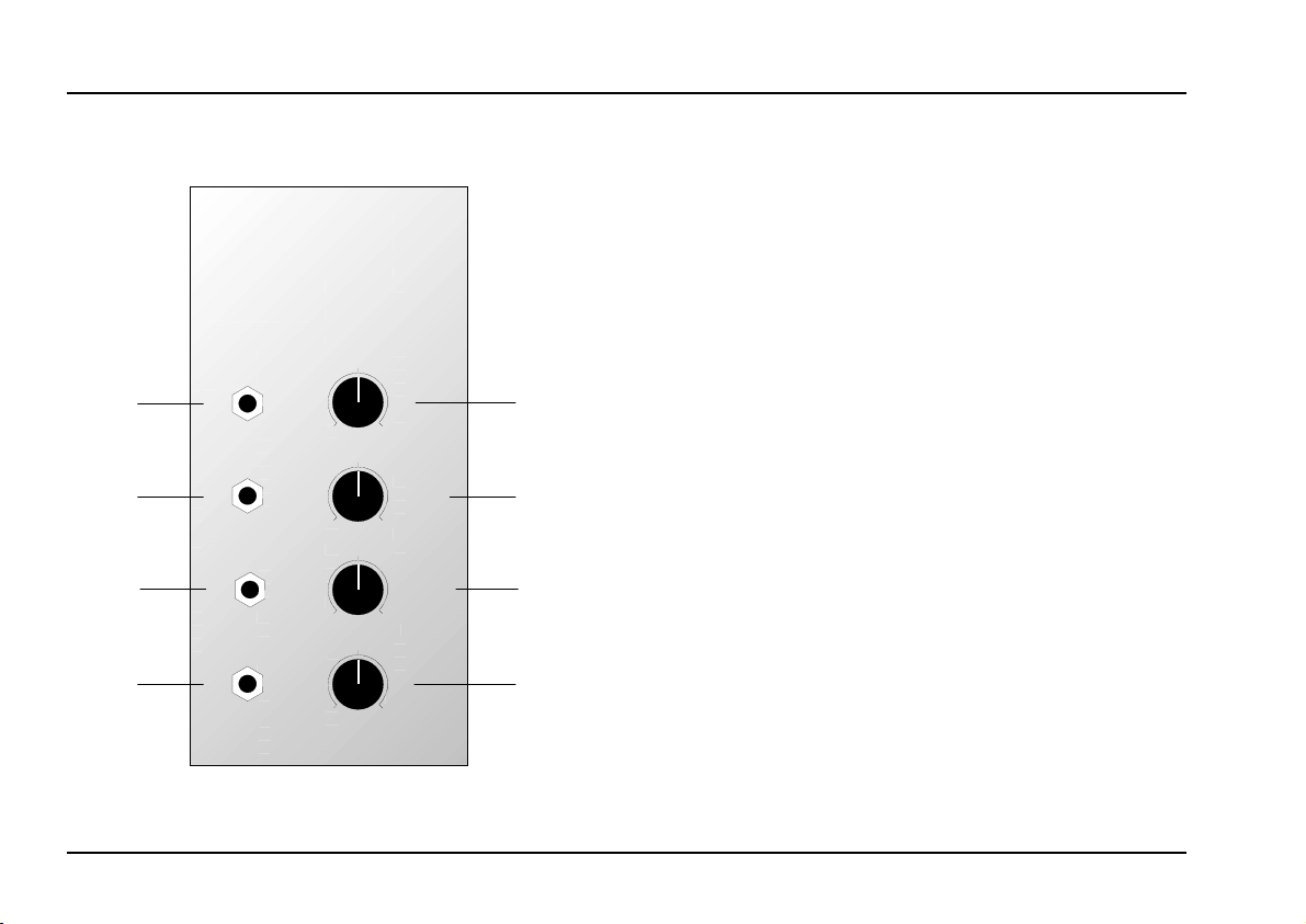
2. Overview
ext. Feedb.
Rev e rb
A-199
Spring Reverb
Audio
In
In
Out
Mix
Out
SPRV
10
0
10
0
10
0
10
0
Lev e l
Fee d back
Emphasis
Mix
➀
➁
➂
➃
Controls:
Level : Attenuator for the the audio
1
input signal at input !
Feedback
2
: Manual feedback control, resp.
attenuator for external feedback
signal at socket "
Emphasis : Control for accentuation of
3
middle frequencies ~ 2kHz
: Control for setting the relation
Mix
4
between original and reverb signal at mix output $
In- / Outputs:
Audio In : Audio input
!
ext. Feedback In
"
Reverb Out
§
Mix Out : Mix output containing both
$
: Input for external feedback
: Audio output pure reverb signal
original and reverb signal
(relation is adjusted with control
4)
2
Page 3

doepfer
System A - 100
3. Controls
1 Level
Attenuator 1 controls the level of the input signal fed
into socket !.
2 Feedback
Knob 2 controls the share of the reverb signal that
is fed back to the input. Feedback can be adjusted as
far as
A-100, e.g. A-120/121/122/123). The self-oscillation
behaviour depends upon the properties of the springsystem.
self-oscillation
H If external feedback is used this control acts as
an attenuator for the external feedback signal. In
this case the reverb output § is passed through
one or more A-100 modules and then fed back
to socket " (refer to chapter 5: user examples).
3 Emphasis
(as for some filter modules of
Spring Reverb
300 Hz 1.0 kHz 10 kHz
Fig. 1: Effect of emphasis function
A-199
4 Mix
This control adjusts the
and reverb signal appearing at output $.
Pay attention to the notes concerning the position and assembly of the reverb system at the
end of this manual.
relation between original
This control enables the adjustment of the accentuation of middle frequencies
1). This gives more “pressure” or “presence” to the
reverb effect.
(around ~
2kHz, see fig.
To minimize hum noise we recommend the
usage of the special A-100 power supply with
ring core transformer (A-100PSU2) instead of
the standard power supply.
3
Page 4

A-199
Spring Reverb
System A - 100
doepfer
4. In- / Outputs
! Audio In
The audio signal to be provided with the reverb effect
is fed into audio input
" ext. Feedback In
If you want to make use of the external feedback
feature socket " is used as input for the feedback
signal (refer to chapter 5: user examples).
H The feedback input
This means that the reverb output § is used as
feedback signal unless a signal is patched into
socket ". As soon as a plug is inserted into
socket " the internal feedback path is interrupted. Control 2 is the attenuator for the internal
or external feedback signal.
Reverb Out
§
At this output the pure reverb signal is available.
$ Mix Out
.
!
is a normalled socket.
"
5. User examples
Apart from the evident application - i.e. reverb simulation - the module can be used for timbre modification
as spring reverb systems show a very characteristic
sound.
The reasons for this behaviour are (insufficient) mechanical properties of the springs like signal delays,
audio resonances, limited frequency range, acoustic
feedback behaviour, sensitivity to mechanical shocks
and others. But just these features make the spring
reverb unmistakable.
Already the controls Feedback and Emphasis allow a
lot of very interesting sound modifications and unusual
reverb effects.
Fig. 2 shows the realization of a frequency-selective
reverb
frequencies of the original signal are emphasized or
suppressed before the signal is fed into the spring
reverb module A-199. Mixing the original signal with
the frequency-selective reverb signal generates very
interesting sound effects.
. By means of a filter bank (A-128) certain
At this output the
reverb signal is available (relation is adjusted with 4).
4
mix signal
containing original and
Page 5

doepfer
System A - 100
Spring Reverb
A-199
50 Hz
75 Hz
A-128
11 kHz
Audio
In
Audio
Audio
Out
In
SPRV
Mix Out
Mix
: Frequency-selective reverb
Fig. 2
Another field of activity results from the external feed-
feature (see fig. 3). Any sound-processing mo-
back
dule or combination of such modules can be inserted
into the feedback path of the spring reverb module
(represented by “XYZ” in fig. 3). Examples are VCA,
any filter, phaser, frequency shifter, distortion/waveshaper, ringmodulator, vocoder, audio divider and so
on.
A VCA in the feedback path e.g. leads to a voltage
controlled (normal) feedback. Filters or filterbanks in
the feedback path modify the spectral behaviour of the
reverb effect (different to the frequency-selective reverb described shortly). Very unusual sounds result
from ringmodulators, frequency shifters or vocoders
inserted into the feedback path of the spring reverb
module.
A-199
Audio
XYZ
Level
In
Audio
Out
Feedback
Level
ext.
Feedb.
In
Reverb
Out
Mix
Out
SPRV
Emphasis
Mix
Fig. 3: External feedback
5
Page 6

A-199
Spring Reverb
System A - 100
doepfer
7. Position and assembly of the reverb
system / Power supply recommendation
The reverb system used in the A-199 consists in
principle of a transmitter (“loudspeaker”) and a receiver (“microphone”) that are connected via a 3-spring
system. The movement of the “loudspeaker” is transmitted to the “microphone” by the springs and generate in this way the reverb effect.
The receiver (“microphone”) is very sensitive to magnetic fields and has to be mounted therefore in a
position with minimal interferences caused mainly by
the transformer of the A-100 power supply mounted at
the rear panel of the frame.
For this reason the black reverb system is connected
with 2 RCA phono cables to the A-199 module. Pay
attention to the colors if you disconnect the reverb
system: red jack plug into red socket (labelled INPUT).
The fixed mechanical connection between pc board
and reverb system used in the first A-199 modules did
not stand the test.
Therefore one has to find out the best position for the
reverb system creating a minimum of hum noise. As a
clue the reverb system should be placed as far as
possible from the transformer of the A-100 power
supply (normally mounted at the lower right side on the
rear panel). Normally the top left position in the frame
is a good one but the rotation of the reverb system
affects the hum noise too. The best position depends
upon many factors and has to be found out by trial and
error. It is also possible to mount the reverb system
outside the A-100 frame. But we recommend this only
for fixed installations of the A-100 frame.
As soon as the best position is discovered the reverb
system is fixed with double-face self-adhesive tape or
screws and nuts at this position. One may use the left,
top, or rear panel of the A-100 frame to mount the
reverb system. If screws are used 2 of them are
sufficient. If necessary 2 holes have to be drilled into
one of the panels. If the top or bottom cover is used
the holes in the covers fit to the holes of the reverb
system.
Additonally the springs of the reverb system are protected during transport with foamed plastic material.
One has to remove this transportation protection before installing the module. In case that the springs stick
together one has to separate them very carefully.
Otherwise the module will not work correct.
As the hum noise is mainly caused by the magnetic
field of the power supply transformer we recommend
the usage of the special A-100 power supply with ring
core transformer (A-100PSU2) instead of the standard
power supply (A-100NT12) for all A-100 systems that
include an A-199 module.
6
 Loading...