

Page 1
doepfer
A-198
Trautonium / Ribbon Ctr.
Gate
Pos ition
Hold
System A - 100
1. Introduction
Module A-198 is a so-called Trautonium resp. Ribbon Controller. It provides variable Control Voltages
and Gate signals generated by combined
Off
On
pressure sensor. The controlling element of the A198 is a linear position sensor (length about 50 cm)
that has available a pressure sensor too.
Trautonium / Ribbon Controller
A-198
position /
CV
Gate
CV
Control
Board
Scale
Pressure
Thres
Scale
Touching the sensor with a finger generates a Control Voltage
the finger. The Scale - i.e. the relation between
position difference and voltage difference - is adjustable
Hold switch is used to determine if the CV voltage is
held after removing the finger or if the voltage jumps to
0V. In the last case (Hold = off) a
derived from the CV voltage whenever a finger touches the sensor (e.g. for triggering an Envelope Generator / ADSR).
A pressure sensor made of conductive rubber arranged below the position sensor generates a
Control Voltage that increases with higher pressure
of the finger. Even for this CV the Scale is adjustable.
A
second Gate
pressure exceeds a certain value. The Gate Threshold is adjustable at the front panel.
that is
with a potentiometer at the front panel. A
proportional to the position of
signal is
Gate
second
signal is triggered as soon as the
1
Page 2
A-198
Trautonium / Ribbon Controller
System A - 100
doepfer
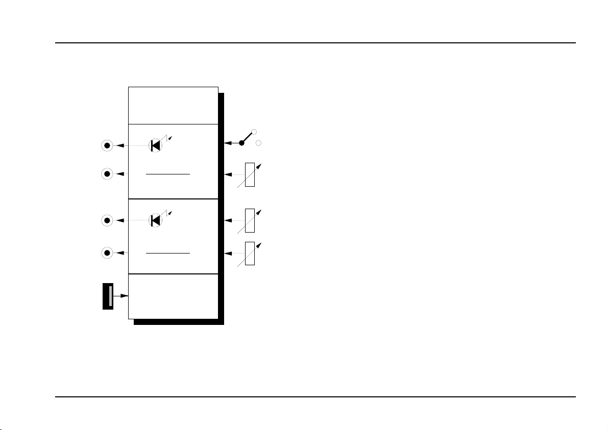
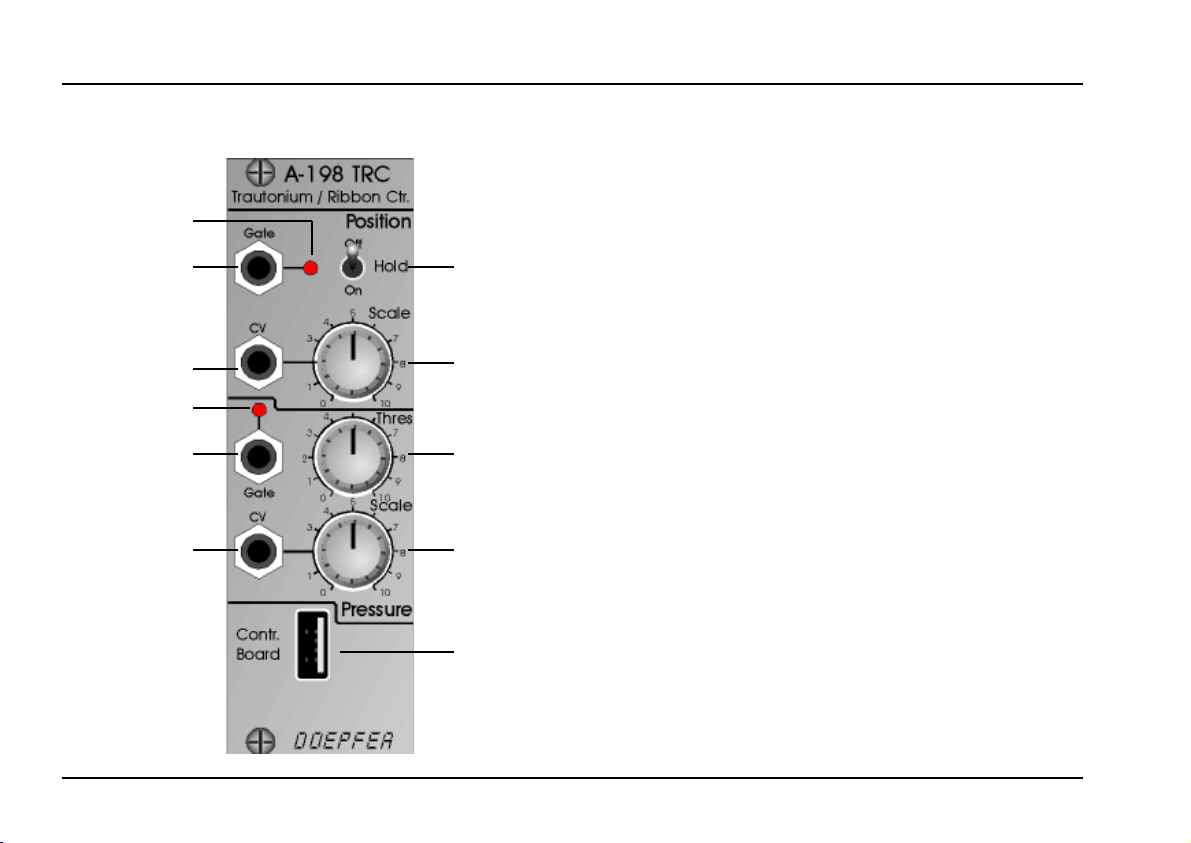
2. Overview
3
"
!
5
$
§
2
1
4
6
%
Controls:
1 Scale : Scale / spread control for Position Con-
trol Voltage output
Hold : Hold function switch
2
3 LED : Gate signal indicator for Position Gate at
output " (active only if Hold = off)
Thres : Threshold control for Pressure Gate si-
4
gnal at output
LED : Gate signal indicator for Pressure Gate at
5
output $
6
: Scale / spread control for Pressure Con-
Scale
trol Voltage output
!
$
§
In / Outputs:
: Position Control Voltage output
CV
!
Gate : Position Gate output (active only if Hold =
"
off)
: Pressure Control Voltage output
CV
§
Gate : Pressure Gate output
$
Contr. Board
%
: Connector for manual (USB type)
Do not connect USB devices to this socket!
A
2
Page 3
doepfer
System A - 100
Trautonium / Ribbon Controller
A-198
3. Controls
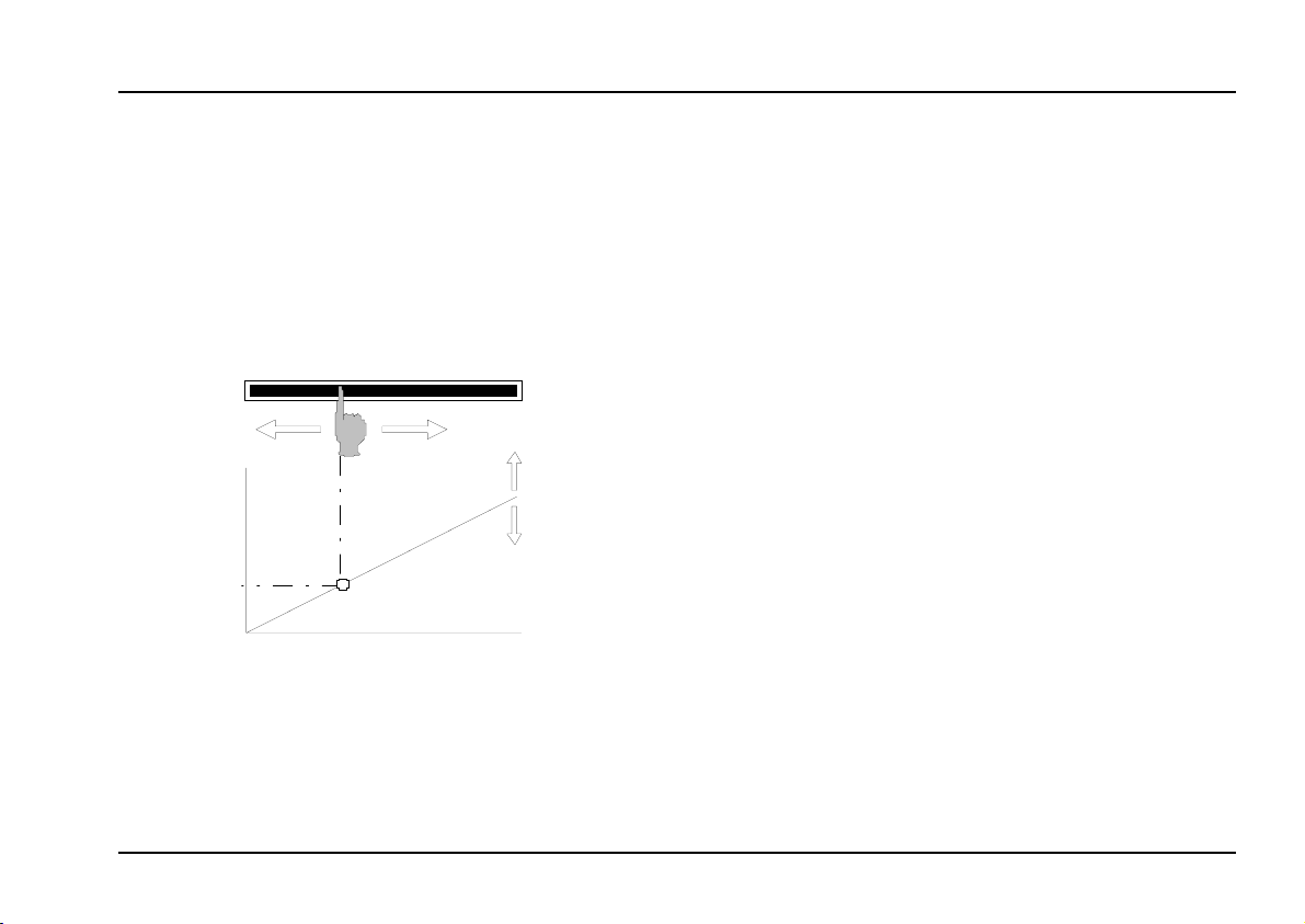
1 Scale
The position sensor of the A-198 is in principle a
linear potentiometer that is activated whenever a
finger touches the sensor. Consequently the relation
between the position of the finger and the Control
Voltage CV
CV
is linear
POS
Ribbon Sensor
PO S
Fig. 1: Connection between position, Control Vol-
tage CV
The
, i.e. the connection between position diffe-
Scale
rence and voltage difference, is adjusted with control
1 (see fig. 1).
too (see fig. 1).
and Scale
POS
Scale
Pos it ion
P
If CV
is used to control the VCO pitch
POS
the scale is adjusted with control 1 so that
the position difference corresponds to the
desired spread, e.g. 25 cm for one octave.
2 Hold
This switch determines the behaviour of the position
control voltage CV
the sensor:
Off :CV
drops to 0V and the Gate output "
POS
turns from high to low. This is the same mode
that was available in the Trautonium.
The last control voltage before the finger was
On :
removed is held with an internal S&H circuit.
In this mode the Gate function at output " is
not active (Gate is permanently high). This
mode was not available in the Trautonium.
In the Off position of the Hold switch the control
voltage CV
drops to 0V as soon as the finger is
POS
removed. If the Gate output " is used to trigger an
Envelope Generator (e.g. A-140, A-141), that controls
the loudness of a VCA or the timbre of a VCF, the
Release time of the Envelope Generator should be
set to zero so that the dropping tone is muted. This is
identical to the behaviour of the Trautonium. Even for
if the finger is removed from
POS
3
Page 4

A-198
Trautonium / Ribbon Controller
System A - 100
the Trautonium the sound disappears immediately if
the finger is removed (no release).
Gate
doepfer
POS
3 LED
The LED 3 monitors the
is triggered by touching the position sensor (active
only in the Off position of the Hold switch).
Thres
4
Control 4 is used to set the Trigger Threshold above
which a Gate signal is generated (see fig. 2). Whenever the pressure control voltage exceeds the threshold
the Gate output $ turns to high.
signal at output " that
Gate
5 LED
The LED 5 monitors the Gate signal at output $ that
is generated whenever the pressure control voltage
exceeds the threshold adjusted with control 5.
6 Scale
The pressure Scale, i.e. the connection between pressure and the voltage CV
adjusted with control 6.
generated at output §, is
PRES
t
Gate
PRES
t
Pressure
Threshold
Touch Release
: Connection between the Gate signals and the
Fig. 2
finger pressure (Gate
is shown for Hold = Off)
POS
t
The pressure sensor is made with conductive rubber
and does not work as accurate as the position sensor.
The resistance of the conductive rubber changes with
varying pressure and causes a variable voltage. But
the coherence between pressure and resistance/voltage is not very accurate - except that an increasing
pressure will cause an increasing voltage. Even some
difference of the pressure sensor behaviour over the
length of the manual may be possible as the conductive rubber has tolerances over this length.
4
Page 5

doepfer
System A - 100
Trautonium / Ribbon Controller
A-198
4. In- / Outputs
! CV
The position dependent Control Voltage CV
available at this output.
" Gate
The position dependent Gate signal Gate
lable at this output (active only in the Off position of the
Hold switch).
POS
§ CV
The pressure dependent Control Voltage CV
available at this output.
$ Gate
The pressure dependent Gate signal Gate
available at this output. Whenever the pressure control voltage exceeds the threshold adjusted with control 4 the Gate output $ turns to high.
PRES
is
POS
is avai-
is
PRES
is
% Contr. Board
The position and pressure sensors are located in a
separate metal frame. The connection between the
module and the sensor frame is made by a 4 pin cable
(same connectors and cable as used for USB connections). Socket % is used for the junction cable to the
sensors. The junction cable and the metal frame that
contains the sensors is included with A-198 manual.
A It is not allowed to connect any USB
device to socket
%%%%
! The USB device
connected to the socket and the A198 module will be destroyed and the
warranty for both devices is void !
5
Page 6

A-198
Trautonium / Ribbon Controller
System A - 100
doepfer
5. User Examples
In the first place module A-198 and the accessory
position/pressure sensor is used to emulate the manual of the Trautonium. For details concerning the
principles of the Trautonium please look at our web
site www.doepfer.com or other web sites that deal with
the Trautonium subject. In combination with the Subharmonic Oscillator A-113, the Trautonium Formant
Filter A-104 and some other modules a complete
reproduction of Oskar Sala’s Mixtur Trautonium is
possible.
Another evident application is the usage as a manu-
ally controlled voltage source
continuously variable analog voltages and two gate
signals that are derived from these voltages. Here are
some typical examples:
as Pitch CV for one or more VCOs
CV
•
POS
Unlike a normal keyboard - that has only certain
voltages (normally 1/12 V grid) and consequently
only certain frequencies (semitones) available - the
A-198 manual outputs a infinitely variable voltage
CV
that allows any VCO frequency, especially
POS
finger-controlled glide effects and vibratos. By
means of the Quantizer A-156 it is possible to
generate semitone, scale or other intervals if
desired. Moving the finger up and down the position
sensor arpeggio-like effects are possible.
that generates two
The gate signal Gate
that is generated whenever
POS
the position sensor is touched (hold switch in the Off
position) an envelope generator (ADSR) can be
triggered. The Release control of the ADSR should
be set to zero (see remark on pages 3/4).
• CV
CV
as “After Touch“
PRES
can be used to control the loudness of a
PRES
VCA or the filter frequency of a VCF with the pressure applied to the pressure sensor while CV
drives the pitch of the VCO(s).
and
• CV
POS
CV
Both control voltages CV
PRES
as
any controller
POS
and CV
can be used
PRES
to control any parameter in the A-100 that is voltage
controlled, e.g. phase or frequency shifting (A125/A-126), panning (A-134), morphing (A-144 +
A-135), pulsewidth (any VCO), LFO speed (A-147).
The modulation intensity (e.g. the amplitude modulation of a VCA, frequency modulation of a VCF or
VCO, pulse width modulation of a VCO) can be
controlled by CV
POS
and CV
. For this the signal
PRES
level of a LFO or VCO is controlled by a VCA whose
control voltage is CV
POS
or CV
. Another applica-
PRES
tion is to add another sound (e.g. noise or sampler
or second VCO) dependent on CV
• Gate
POS
and
Gate
PRES
as
"Event Controller"
PRES
.
The Gate signals can be used to trigger events, e.g.
starting or stopping the Analog/Trigger Sequencer
A-155 or switching between sound sources by
means of the Voltage Controlled Switch A-150.
POS
6
Page 7

doepfer
System A - 100
Ribbon Sensor
Trautonium / Ribbon Controller
A-198
Po s it io n
Gate 1
A-198
Contr.
Boar d
Pressure
Pit ch
CV
CV
VCO
Ring
Mod.
VCO
LFO
Fig. 3: “Sound of a hand passing over a wineglass”
P By means of the CV-to-MIDI Interface A-192
the output voltages of the A-198 can be
converted into any MIDI Controller (for details see A-192 user's manual).
The patch in fig. 3 simulates the sound of a hand
passing over a wineglass. The position control voltage
defines the pitch of a the VCOs. The position gate
signal triggers the ADSR that controls the loudness
progress of the sound.
Audio
Out
Mixer
VCF
VCA
ADSR
With the ring modulator and suitable settings of the
mixer, LFO frequency, filter frequency and resonance
the typical bell-like sound is generated. The LFO provides the vibrato. Optionally the filter frequency can be
controlled by the pressure voltage.
With different settings of the mixer and the filter metallic sounds are generated. In combination with fast
envelopes one obtains percussive sounds that remind
of hitting or plucking a string.
7
Page 8

A-198
Trautonium / Ribbon Controller
Ribbon Sensor
CV
POS
A-198
Gate
A-150
POS
System A - 100
CV In
CV Out
Trig. In
A-162
Trig. Out
Transpose CV 1+2
A-156
QNT
Options
doepfer
Minor
Chord
+7
A-150A-177
Foot Sw it c h
Fig. 4: A-198 as a "keyboard"
The patch of fig. 4 shows the application of the A-198
as a "keyboard". A foot switch in combination with the
8
VCO VCF
ADSR
A-177 is used to select between quantized and non
quantized operation. The first of the two voltage controlled switches of the A-150 defines if the position
voltage CV
quantized with the A-156. The setting of the quantizer
VCA
ADSR
is fed directly to the VCO or if CV
POS
POS
is
Page 9

doepfer
System A - 100
Trautonium / Ribbon Controller
A-198
determines if all semitones or only tones of the minor/
major scale or notes of a chord are allowed. For details
please refer to the A-156 manual.
The second of the two voltage controlled switches of
the A-150 module defines if the position gate Gate
POS
or the trigger output of the quantizer is fed to the gate
input of the ADSR. Additionally a Trigger Delay A-162
is used to lengten the short trigger signal coming out of
the A-156.
Summary:
Without quantizer each touch of the position sensor
•
generates a gate signal Gate
that triggers the
POS
ADSR for filter and loudness.
In the quantized mode the A-156 generates short
•
trigger signals (~ 10 ms) at each new quantization.
These short pulses are expanded to the desired
length by means of the Trigger Delay A-162. The
output of the Trigger Delay triggers the ADSR for
filter and loudness.
The patch can be extendend in manifold ways:
• Feeding a keyboard or sequencer pitch control
voltage to the transpose input of the quantizer (see
fig. 4) transposes the sounds played on the A-198.
• Use the pressure voltage CV
gate Gate
for additional modulations (e.g. filter
PRES
and the pressure
PRES
frequency, pulse width modulation, frequency modulation of VCO or VCF, VCF-ADSR or third ADSR
triggered by Gate
, third ADSR may be used to
PRES,
control modulation depth or frequency of a VCLFO
for modulations).
You may add even additional controllers, e.g.
• Pitch: Position sensor (A-198)
or Theremin (A-178)
Frequency modulation
•
(VCO): Pressure sensor (A-198)
• Filter frequency: Light controller (A-179)
or Position sensor (A-198)
or Pressure sensor (A-198)
• Glide on/off: Foot switch (A-177)
• Loudness: Theremin (A-178)
or Foot controller (A-177)
9
Page 10

A-198
Trautonium / Ribbon Controller
6. Patch-Sheet
System A - 100
doepfer
The following diagrams of the module can help you
recall your own Patches. They’re designed so that
a complete 19” rack of modules will fit onto an A4
sheet of paper.
Photocopy this page, and cut out the pictures of
this and your other modules. You can then stick
them onto another piece of paper, and create a
diagram of your own system.
Make multiple copies of your composite diagram,
and use them for remembering good patches and
set-ups.
P • Draw in patchleads with colored
pens.
• Draw or write control settings in the
little white circles.
A-198 TRC
Trautonium / Ribbon Ctr.
Gate
CV
Gate
CV
Contr.
Board
Pos ition
Off
On
0
0
0
Pressure
Hol d
Scale
10
Thres
10
Scale
10
A-198 TRC
Trautonium / Ribbon Ctr.
Gate
CV
Gate
CV
Contr.
Board
Pos ition
Off
On
0
0
0
Pressure
Hol d
Scale
10
Thres
10
Scale
10
10
 Loading...