

Page 1

doepfer
A-196
CV In
Out
In 1
In 2
(Signal)
Out
Out
PLL
VCO
Off s et
Range
PC
locked (2)
Type
LPF
Frequ.
System A - 100
1. Introduction
Module A-196 contains a so-called Phase Locked
Loop circuit (PLL). A PLL consists of three parts:
VCO (linear voltage-controlled oscillator with rectangle
output), phase comparator (PC), and low-pass filter
(LPF). The three parts are connected in the A-196 with
normalled sockets to form the standard closed-loop
PLL frequency-feedback system. The normalled sockets allow individual access to each part of the PLL
and enable other patches than the standard PLL (e.g.
insertion of external modules).
The VCO is equipped with the controls Range and
Offset. The range switch is used to select one of three
frequency ranges. The Offset control defines the maximum frequency of the VCO.
The module contains three different types of phase
comparators that are selected with a 3-position
switch.
The LED indicates if the PLL is locked for PC2 , i.e. if
the frequency of the internal VCO is the same as the
frequency of the external input signal.
PLL
A-196
The frequency of the built-in low pass filter is manually adjusted with the frequency control.
1
Page 2

A-196
PLL
System A - 100
doepfer
2. Basic principles
The three units VCO, phase comparator (PC) and low
pass filter (LP) form a standard closed-loop frequencyfeedback system: The VCO output (linear response,
rectangle output) is compared with an external signal
(e.g. A-110 VCO) in the PC. The PC output is a digital
high/low signal that indicates if the frequency resp.
phase difference of the two input signals is negative,
zero or positive. This signal is processed by the LP to
generate a smooth control voltage that controls the
frequency of the VCO. The units VCO, PC and LPF
form a frequency feedback loop that works like this:
The CV (LP output) increases (decreases) as long as
the external frequency is higher (lower) than the frequency of the internal VCO and stops increasing as
soon as both frequencies become identical.
But there are some stumbling blocks: Different types
of phase comparators with advantages and disadvantages can be made. Some phase comparators e.g.
even lock at harmonics, i.e. if the two frequencies to be
compared are integer multiples. For some applications
this "fault" may be used to create interesting effects.
The A-196 contains 3 different types of phase comparators: PC1 is a simple exclusive OR, that even locks
at harmonics. PC2 is a so-called RS flipflop and PC3 a
more complex digital memory network. The user can
select one of the three phase comparators with a
3-position switch. When PC2 is used a LED displays
the "locked" state, i.e. when the frequency of the
internal VCO is identical to the external frequency.
Special attention has also to be directed to the fre-
quency of the LP. To obtain a smooth control voltage
for the VCO the frequency of the LP has to be much
smaller than the lowest frequency of the internal or
external audio signal. Otherwise the frequency of the
internal VCO will jitter or wobble around the correct
frequency. But for special effects this frequency jitter
can be used intentionally.
Example: frequencies in the range 50Hz...1kHz have
to be processed with the PLL. Therefore the frequency
of the LP has to be about 10Hz or even less. Such a
low frequency of the LPF causes a noticeable slew of
the internal VCO. When the frequency of the external
signal jumps e.g. between 50Hz and 1kHz it takes
about 0.1 second until the internal VCO reaches the
new frequency (like portamento). Consequently one
has to find a compromise between the frequency jitter
and portamento. But these remarks are valid only for
the "ideal" working PLL. As the A-196 is used in a
musical enviroment these "problems" and "disadvantages" with jitter and slew time lead to additional
musical applications like portamento effects, wobbling
frequencies or harmonic locking according to the type
of frequency comparator and time constant of the PLL
low pass filter.
2
Page 3
doepfer
System A - 100
PLL
A-196
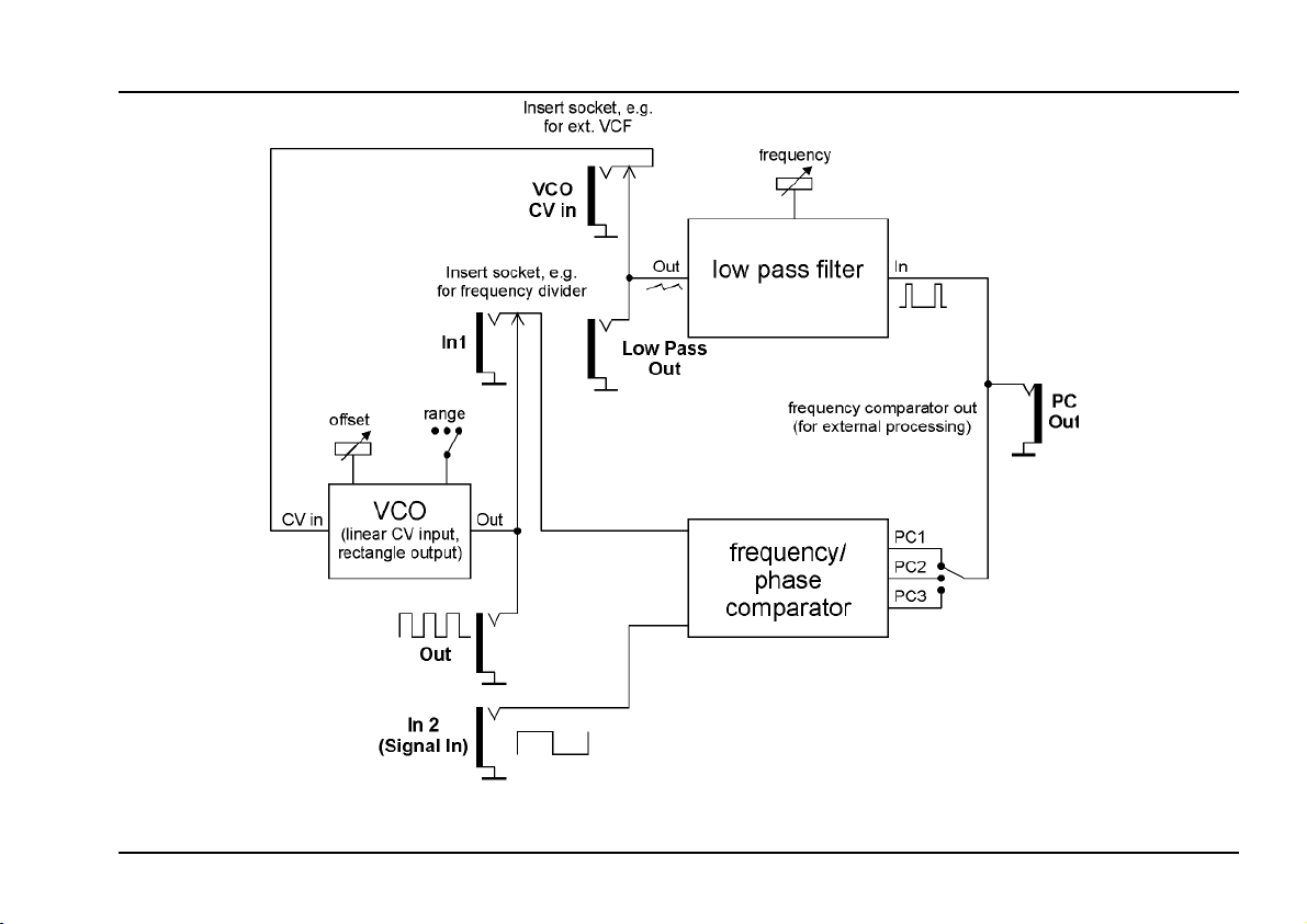
Fig. 1: Internal construction of the A-196
3
Page 4

A-196
PLL
System A - 100
doepfer
3. Overview
!
"
§
$
&
2
1
4
3
%
5
Controls:
1 Range : Three-position frequency range switch
for the VCO
2 Offs. : Frequency offset control
3 Type : Three-position switch to select one of
the three phase comparators
4 LED : lock display for PC2
5 Frequ.: Frequency control of the low pass
filter
In- / Outputs:
! VCO CV In : Control voltage input of the VCO,
internally normalled to socket %
" VCO Out : VCO output (rectangle), internally
normalled to socket §
§ PC In 1 : Signal input 1 of the PC, internally
normalled to socket "
$ PC In 2 : Signal input 2 of the PC for external
signal
% Out : PC output, internally connected to the
low pass filter input
& Out : Low pass filter output
4
Page 5

doepfer
System A - 100
PLL
A-196
4. Controls
1 Range • 2 Offs.
The frequency range of the internal VCO is selected
with the switch 1.
Control 2 is used to adjust the frequency offset, i.e.
the maximum frequency within the range selected
with the switch 1. The table shows the VCO frequencies obtainable with different settings of range and
offset (with a control voltage ~ 0...+5V at input !).
Range Offset = 0 Offset = 5 Offset = 10
low
mid
high
3 Type
The type of Phase Comparator (PC) is selected with
this switch. Three PC types are available:
• PC 1 Exclusive or gate (Exor)
• PC 2 RS Flipflop
• PC 3 more complex digital network
2 Hz - 50 Hz 2 Hz - 200 Hz 2 Hz - 1 kHz
20 Hz - 500 Hz 20 Hz - 2 kHz 20 Hz - 10 kHz
200 Hz - 5 kHz 200 Hz - 20 kHz 100 Hz - 100 KHz
Each phase comparator has its special advantages
and disadvantages. E.g. PC1 locks even at harmonics,
i.e. integer frequency multiples of the external signal
and the internal VCO. This is a disadvantage for the
standard PLL idea but may be useful for certain musical effects. One has to find the most suitable PC for
each application.
4 LED
This LED lights up if the PLL is locked for PC2, i.e. if
the frequency of the external signal is identical to the
frequency of the internal VCO.
5 Frequ.
This control is used to adjust the frequency of the
internal low pass filter.
The internal LP can be replaced by an external LP. The
external LP has to be DC coupled and work even at
very low frequencies (some Hz range)! Consequenctly
normal audio VCFs are not suitable. The VC slew
limiter A-171 can be used instead. The "raw" PC output
& or the pre-filtered output % can be used as input for
the external filter/slew limiter. In this case the output of
the external filter/slew limiter is used as control input !
for the VCO.
5
Page 6

A-196
PLL
System A - 100
doepfer
5. In- / Outputs
! CV In
This socket is the control voltage input of the internal
VCO. The socket is normalled to the internal filter
output, i.e. the CV for the VCO comes from the filter
output provided that no plug is inserted into socket !.
P
" Out
Socket " is the VCO output signal (rectangle waveform). Internally this signal is connected to input 1 of
the phase comparator.
§ In 1
This socket is input 1 of the phase comparator. The
socket is normalled to the internal VCO output ", i.e.
input 1 of the PC comes from the internal VCO provided that no plug is inserted into socket §.
The VCO of the A-196 can be used as a
simple rectangle VCO with linear control
response. To control the VCO frequency a
suitable voltage has to be fed into socket !. To
obtain scale and offset control an A-129-3 or
A-167 can be used.
$ In 2 (Signal In)
This socket is the second signal input of the PC. The
external PLL signal input (e.g. VCO A-110 or frequency divider A-163) is connected to this socket.
% Out
This socket is the output of the currently selected
phase comparator (selected with switch 4). It is a
digital signal (high/low/tri state) that is internally
connected to the low pass filter input. This output can
be used to process the PC signal with external modules (e.g. VC slew limiter A-171). The processing modules have to be DC coupled as sub-audio frequencies
have to be processed ! Only for special effects even
AC-coupled modules (e.g. normal audio filter) may be
used.
& Out
This socket is the low pass filter output. The socket
is internally connected to the control input of the the
VCO via the normalling socket !. The same notes as
in the preceeding paragraph are valid. But the PC
output is already pre-filtered with the internal low pass.
A combination of the internal low pass and an external
processing module (e.g. A-171) can be used to generate the desired VCO control voltage.
6
Page 7

doepfer
6. User examples
System A - 100
PLL
A-196
Frequency Multiplication
A very important application of the A-196 is frequency
multiplication. For this the output of the internal VCO
is connected to the input of an external frequency
divider (e.g. the VC frequency divider A-163 or the
A-160). The output of the divider is connected to input
§ of the phase comparator (see fig. 2). By this the
internal VCO oscillates at a multiple of the frequency of
the external signal. The multiple is defined by the
setting of the frequency divider. For this application
PC2 is recommended as it does not lock at harmonics.
Example: Setting the A-163 to a dividing factor 5
causes the fivefold frequency at the VCO output of the
A-196 compared to the frequency of the external signal
fed into input 2 of the PC (multiple A-180 at the VCO
out of A-196 required, not shown in fig.2).
Using the A-163 consequently leads to a voltage controlled frequency multiplication. Modulating the A-163
dividing factor passes through several pseudo-
harmonics, "pseudo" as the waveform of the A-196
VCO is rectangle in contrast to real sine shaped harmonics.
Out
In 1
In 2
VCO
Out
A-196
PLL
PC
CV
CV In
In
Out
A-163
VDIV
Man ual
Fig. 2: Frequency multiplication with A-163
Grafic VCO
Frequency multiplication can be used to generate the
clock signal for a graphic VCO. For this e.g. the
A-155 can be used even though it is equipped with
rotary controls instead of faders as usual for graphic
VCOs.
For this the Clock input of the A-155 is connected to
the A-196 VCO output. The frequency of an external
VCO (e.g. A-110) is multiplied with the A-196 by 8 - as
the A-155 has 8 steps. The waveforms of the audio
signals that appear at the two Pre-Outputs of the A-155
can be adjusted with the analog controls of the A-155
like a graphic VCO. The audio frequency is identical to
the controlling "master" VCO (e.g. A-110).
7
Page 8

A-196
PLL
System A - 100
doepfer
A very interesting variant of this patch is the usage of
the 8 external inputs of the lower A-155 row. Connect
these inputs to 8 different automatically changing control voltages (e.g. LFO A-145/146/147, ADSR A140/141/142, Random voltages A-118/A-149-1, morphing controller A-144) or even audio signals. Automatically varying waveforms will appear.
Another application is the generation of clock signals
for switched capacitor filters (SCF). For these types
of filters the filter frequency is defined by the frequency
of an external clock signal. So far no filters of this type
are available as A-100 modules but we are about to
experiment with SCFs.
The A-196 is a very experimental module and some
of its functions cannot be described straight forward as
for other modules. Rather the user should try out the
possibilities by trial and error.
E.g. the frequency jitter (i.e. actually too high LP frequency for optimal PLL operation) or frequency slew
(i.e. actually too low LP frequency) can be used intentionally to obtain certain effects.
Even the upper frequency limits of the VCOs can be
used on purpose ("frequency clipping").
Usually the three phase comparators behave completely different within the same patch so that this peculiarity leads to additional sound experiments.
More patches and audio examples can be found on
our web site www.doepfer.com on the A-196 info page.
8
 Loading...