

Page 1
doepfer
System A - 100
1. Introduction
MCV 16
A-191
H
S0/
LFO
T0/
LFO
S90/
LFO
T315/
C16
MIDI
In
Frequ. +
Frequ. –
Mode
MIDI /
SG
MCV16
Reset/
Store
Connecting the A-191 to the system bus
requires an additional special power sup-
ply (+5 V / 50 mA).
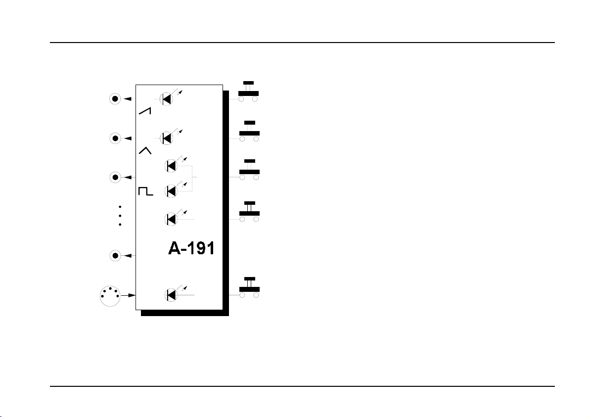
Module A-191 is a combination of a MIDI-CV inter-
face
and a
Shepard Generator
. Most of the controls,
indicators and in/outputs have a double function; there
is a switch which toggles between the two sets of
functions.
In use as a MIDI-CV interface, 13 of the 16 control
voltage outputs are dedicated to sending voltages
converted
from a particular MIDI controller
(such as
Mod Wheel, Volume, Pitch Wheel, Aftertouch, etc.).
Controller messages on your
chosen MIDI channel
are converted into voltages in a range from 0 to 5 V.
The other three sockets output an internal LFO gene-
rated in sync with MIDI clock, in three waveforms:
sawtooth, triangle and rectangle.
In use as a Shepard Generator, the sockets output
eight different phases each of a triangle and sawtooth
wave. Using a variety of modules, the Shepard
Generator can create some interesting psychoacoustic effects.
All A-191 settings can be saved into non-volatile
memory
.
1
Page 2
A-191
MCV 16
System A - 100
doepfer
2. MCV16 - Overview
MCV16
MIDI-CV / SHEPARD
S0 /LFO
T0 /LFO
S90 /LFO
T90 /AT
S180 /Pit
T180 /C1
S270 /C2
T270 /C4
S45 /C5
T45 /C6
S135 /C7
T135 / C8
S225 / C10
T225 / C11
S315 /C12
T315 / C16
Control
Control
Freq. +
Freq. –
Reset/
Store
Learn
Mode
Fast
Slow
–
MCV
Shepard
MIDI
In
➀
➁
➂
➄
➅
➇
➆
➈
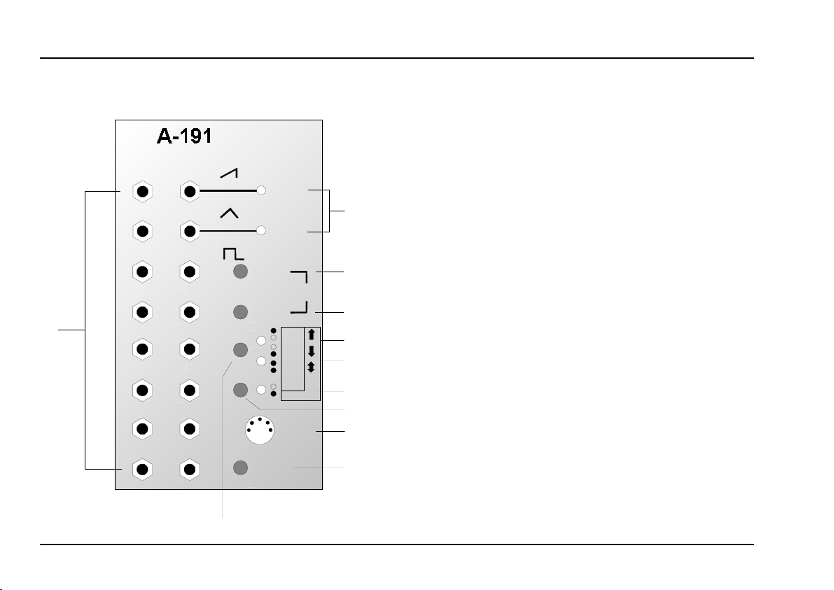
Controls and indicators
LEDs : Indicators for triangle and/or sawtooth
1
waveform frequency
Freq. + : Button to increase LFO frequency
2
3 Freq. – : Button to decrease LFO frequency
4
5, 6
: Shepard function switch
Mode
LEDs : Shepard function indicators
7 Mode : Switch to select either Shepard Gene-
rator or MIDI interface
LED : Indicator to show which out of the
8
Shepard Generator or MIDI interface
is selected
Reset/Store
9
: Button for saving set-ups or resetting
Shepard Function Generator
In- / Outputs
! sockets : CV outputs from the Shepard Genera-
tor and MIDI-CV interface (see text)
" MIDI In : MIDI input socket
➃
2
Page 3

doepfer
System A - 100
MCV 16
A-191
3. Switching between the functions
Because the A-191 has two separate functions in it,
which share some of the controls and outputs, at any
one time it can be used
or as a Shepard Generator. To switch between the two
you simply press a button (see below).
H
The A-191’s controls and in / outputs for
each function are explained in their
respective sections of this manual.
7 Mode button
To switch between functions, press the lowest mode
button 7777
.
8 LED
LED 8 lights when the Shepard Generator is active;
otherwise it’s the MIDI-CV interface which is active.
H If the A-191 receives MIDI clock, LED
flashes (see chapter. 4.2, " MIDI In).
as a MIDI-CV interface
either
4. MIDI-CV interface
4.1 Basics
In its MIDI-CV mode, the A-191 provides a MIDI-CV
converter, and a MIDI-synchronized LFO.
Whenever the A-191 receives
ler messages on the channel you’ve selected, it converts them into control voltages (in a 0 V to +5 V
range), and sends these out on the corresponding CV
outputs. Table 1 on page 4 lists the MIDI controllers,
their corresponding CV output sockets, and their default values.
H After switching your A-100 system on, pres-
sing the Store/Reset button 9 sets the
voltages at the
values (see table 1).
If you’re running your A-100 from a MIDI
8
sequencer, you’ll need to save the appropriate MIDI controller messages at the beginning of a Song, to initialise the A-191’s CV
outputs correctly.
relevant MIDI control-
CV outputs
to the
default
3
Page 4
A-191
MCV 16
System A - 100
doepfer
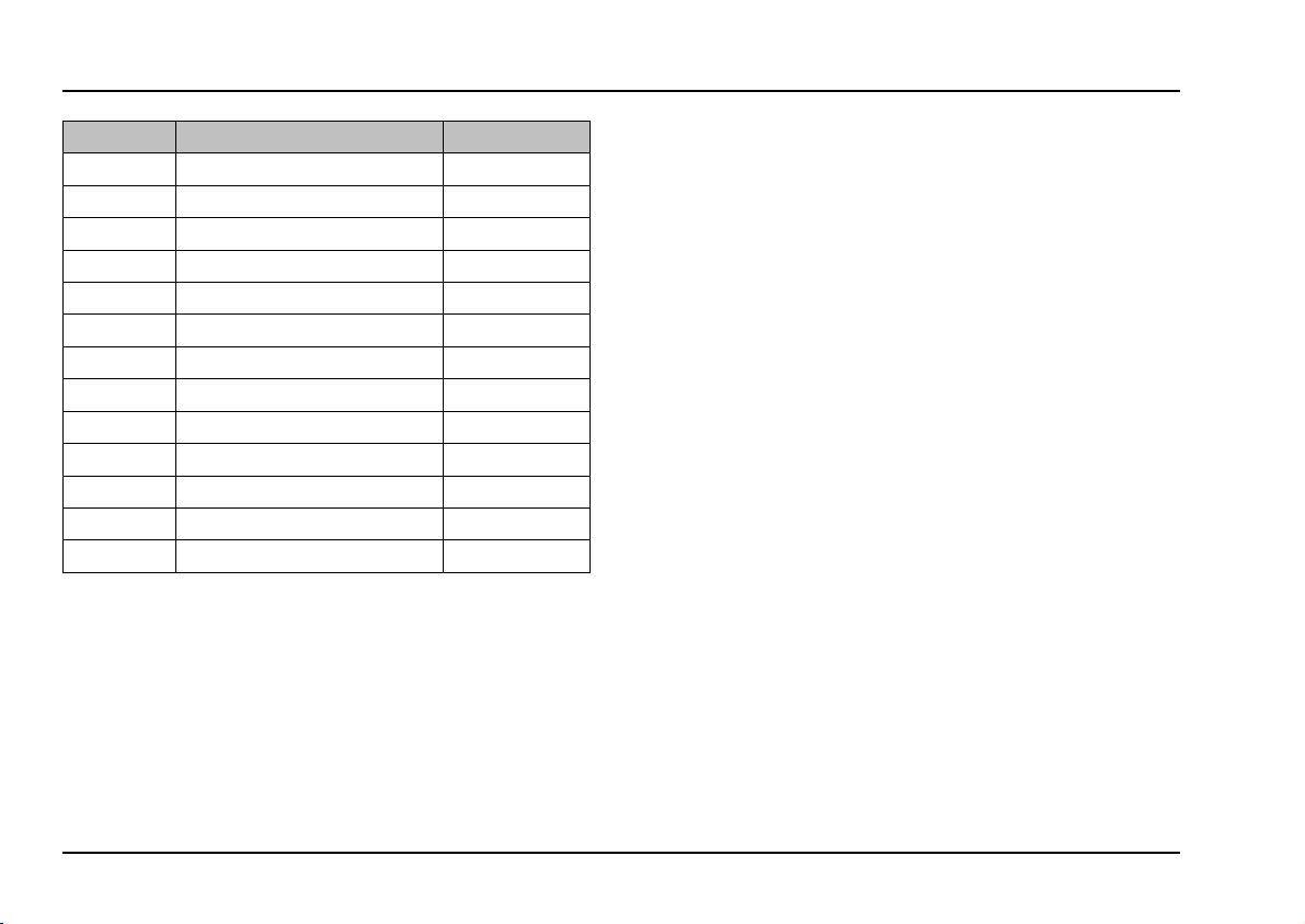
Output corresponding MIDI controller default [V]
AT After Touch 0
Pit Pitch Wheel 2.5
C1 CTRL. #01 - Modulation Wheel 0
C2 CTRL. #02 - Breath Controller 0
C4 CTRL. #04 - Foot Controller 0
C5 CTRL. #05 - Portamento 0
C6 CTRL. #06 - Data Slider 0
C7 CTRL. #07 - Volume 5
C8 CTRL. #08 - Balance 2.5
C10 CTRL. #10 - Pan 2.5
C11 CTRL. #11 - Expression 0
C12 CTRL. #12 0
C16 CTRL. #16 0
Table 1: Valid MIDI controllers, their corresponding CV
outputs, and default values.
The A-191’s internal MIDI-synchronised LFO has three
waveforms - sawtooth, triangle, and rectangle.
This LFO is only active when a MIDI clock is being
sent to the MIDI IN, from a START or CONTINUE
message until a STOP message. LED 8 indicates
that it’s active.
At a STOP message, the voltage at the CV output is
held; at a CONTINUE message, the LFO starts from
this value; and at a START message, the waveform
begins again, starting from 0 V.
The LFO rate can be slowed down by dividing the
clock rate. You set the
divisor
either with
MIDI
controller #92 (Tremolo Depth) or manually, with
buttons 2 and/or 3.
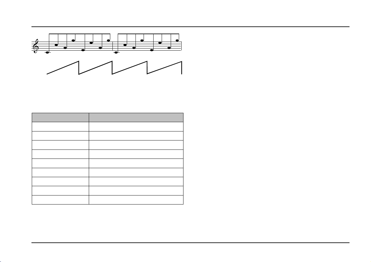
The note length N of a full cycle of the waveform
generated by the LFO follows this formula :
Nth Note = 1/16 x controller value (see Table 2)
So, for instance, in 4/4 time, with a controller value of
8, the note length of a full LFO cycle would be half of a
whole note: that is, the LFO would cycle twice for each
beat in the bar (see Fig. 1).
4
Page 5
doepfer
4
4
System A - 100
Fig. 1: The sawtooth (1/2 note cycle) generated by
a MIDI controller value of 8.
Controller value LFO cycle
0LFO off
11/16
2 2/16 = 1/8
33/16
4 4/16 = 1/4
8 8/16 = 1/2
16 16/16 = 1 whole note
32 32/16 = 2 whole notes
64 64/16 = 4 whole notes
Table 2: Typical values for controller #92 and the
resultant length of the LFO cycle.
MCV 16
H Because the A-191’s LFO is purely a
A-191
soft-
ware device, the following considerations
apply, which it’s well worth remembering.
The A-191 uses an 8-bit D/A converter, whose maximum resolution is 256 steps per 0.02 V. Consequently, the
sawtooth
and
triangle
waves can’t be as
smooth as, for instance, those of the A-145 LFO. The
waveforms on the A-191 LFO are
digital
("stepped").
If you use it to control, eg, a VCO, the result is less of
a smooth continuous pitch sweep, and much more
akin to a glissando. How audible these steps are
depends on the MIDI-Clock tempo, and the divisor
you’ve chosen.
P If the steps are audible (and unwanted), you
can use a Slew Limiter (A-171) to smooth
out the waveforms.
Erratic or sudden changes of tempo or the divisor
will take a whole note to register, before the LFO
changes to this new frequency.
5
Page 6

A-191
MCV 16
System A - 100
doepfer
4.2 Indicators and controls
1 LEDs
The LEDs 1 indicate the frequency of the internal
LFOs. They indicate the state of the sawtooth signal
at output S0 and/or the triangle wave at output T0 .
2 Freq. + • 3 Freq. –
Buttons 2 and 3 have a double function in the MIDICV interface:
Setting LFO frequency
•
Pressing buttons 2 or 3 increases and/or de-
creases the frequency of the internal LFOs.
While buttons 2 or 3 are pressed, LEDs 5 and 6
blink to show the increase or decrease in the LFO
frequency. If you reach the upper or lower limit of
the frequency, the LED stops blinking.
It’s easier and definitely more precise to
H
alter the LFO frequency
#92.
Setting the MIDI input channel
If you simultaneously hold down buttons 2 and 3,
"
learning mode
LEDs 5, 6 and 8 all flashing at once.
" is activated. This is signalled by
by MIDI controller
You can now set the MIDI channel you want the
MCV16 to respond to. To do this, send a valid
controller (see table 1) to the A-191. This automatically ends learning mode, the LEDs go out, and the
MIDI channel of whatever controller was used becomes the input channel for all the MIDI data sent after
this.
LFO frequency and MIDI- input channel are only temporarily stored, unless you save them by pressing
button 9 (see below).
H The labels on LEDs
"--") don’t have a function yet in MIDI-CV
mode, but are hoped to have in a future
update.
and 6 ("Fast", "Slow",
5
MIDI
9 Reset / Store
To
frequency press button 9.
LEDs 5, 6 and 8 light for about a second to confirm
the save procedure has succeeded. At the same time,
all CV outputs are set to their default settings (see
table 1).
the settings for
save
MIDI input channel
and
LFO
6
Page 7

doepfer
System A - 100
MCV 16
A-191
4.3 In- / Outputs
! CV outputs
Sockets ! are the MIDI-CV interface’s CV outputs:
LFO • LFO • LFO
These sockets are the outputs for the sawtooth,
triangle and rectangle waves produced by the inter-
nal LFO.
voltages at the sawtooth and triangle wave outputs.
LEDs 1 and 2 give an indication of the
H Don’t forget that the LFO will only work if a
MIDI clock is being received on the selected
MIDI channel (see chapter 4.1, Basics).
AT • ... • C16
These 13 sockets output the control voltages converted from their respective
1). Their voltage range is from 0 V to +5 V.
MIDI controllers
(see table
" MIDI In
This MIDI input socket should be connected to the
MIDI keyboard or sequencer, etc., that you want to
control the System A-100, with a standard MIDI lead.
As well as converting MIDI controllers After Touch,
Pitch Wheel, #01, #02, #04 to #08, #10, #11, #12 and
#16, and turning them into voltages available at the
corresponding CV outputs (see table 1), the A-191
also responds to MIDI clock - and to MIDI controller
#92 ("Tremolo Depth") for controlling the internal
LFOs.
7
Page 8

A-191
MCV 16
System A - 100
doepfer
4.4 User examples
Modulation-rich synthesizer patch
The example in Fig. 2 shows a ‘classic’ synthesizer
patch: 2 VCOs, VCF (A-122) and VCA (A-130). Modules A-190 and A-191 act as the link to a MIDI key-
board,
THRU from the A-190 is connected to the MIDI IN of
the A-191.
This patch gives a
bilities accessible from velocity, mod wheel, pedals,
and aftertouch:
• VCO 2 level
• Modulation of VCF resonance
and are set to the same MIDI channel. The
vast range of modulation possi-
VCO 2’s amplitude level (ie. volume) can be controlled with a pedal. In this example, the A-190’s
second CV output (CV 2) has been previously
programmed to respond to MIDI controller #04, but
CV output C4 on the A-191 could have equally
well been used.
Filter resonance is modulated by a random vol-
tage source
intensity of this modulation is controlled by the
modulation wheel (output C1 on the A-191).
(the
’s random output). The
A-118
• Amplitude modulation
The intensity of the amplitude modulation created
by the LFO patched into the VCA (A-130) is controlled by aftertouch (output AT on the A-191).
• Overall volume
The overall volume of the output signal sent to the
monitoring system is controlled by MIDI controller #7
(Volume)
be assigned to a pedal, pitch ribbon, etc. on your
master keyboard.
(output C7 on the A-191). This controller can
H If you want to use a MIDI controller which the
A-191 doesn’t support - for instance a
sustain pedal - then you can always set the
A-190 to respond to it, and output it from its
CV2 socket.
MIDI-synchronised LFO
The internal LFO on the A-191 is synchronised to MIDI
clock. This is particularly useful when you’re using a
MIDI sequencer or arpeggiator with the A-100.
An example is shown in Fig. 3. In this patch, the
internal LFO modulates the VCF’s cut-off frequency.
8
Page 9

doepfer
MIDI
Out
System A - 100
MCV 16
A-191
CV 1
MIDI In
A-190
MIDI Thru
CV 2
Gate
C 1
MIDI In
AT
C 7
VCO 1
VCO 2
A-132
Foot
A-118
A-191
Fig. 2: Classic synthesizer patch with multiple modula-
tion possibilities.
A-138a
Mod. Wheel
A-132
A-122
QCV
ADSR 1
LFO
FCV
A-130
ADSR 2
A-132
After Toucn
A-131
Volume
9
Page 10

A-191
MCV 16
System A - 100
doepfer
MIDI -
Sequencer
MIDI
Out
MIDI In
A-190
MIDI Thru
CV 1
MIDI In
LFO
A-191
Gate
: VCF cutoff control with a MIDI-synced LFO.
Fig. 3
Set the LFO frequency so that it completes one cycle
every whole note.
During the first four 1/8th notes of the sequence, the
filter is opening; and in the last four 1/8th notes, it’s
closing.
10
VCO
VCF
VCA
ADSR
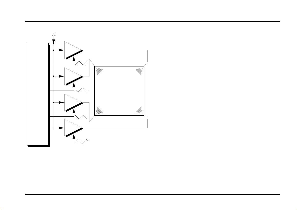
Another example of MIDI-synchronised use of the
internal LFO is shown in Fig. 5. Two A-125 phasers
set to opposite phase are sent to two audio outputs
and OutR) to produce MIDI-synchronised spa-
(Out
L
tial effects
.
Page 11

doepfer
R
System A - 100
MCV 16
A-191
VCO
MIDI -
Sequencer
MIDI
Out
CV 1
MIDI In
A-190
MIDI Thru
Gate
MIDI In
LFO
A-191
Fig. 4: MIDI-synchronised "stereo" phasing.
VCF
A-175
VCA
ADSR
VCP 1
VCP 2
CV
Out
CV
L
Out
11
Page 12

A-191
MCV 16
System A - 100
doepfer
5. Shepard generator
5.1 Basics
A Shepard generator is a modulation oscillator,
which produces various phase inversions of triangle
and sawtooth waveforms at its outputs.
The way the Shepard generator is set up produces
various psycho-acoustic phenomena, such as the
‘barber-pole’ effect - seemingly never-ending upward
or downward spirals of pitch, filter settings, phasing,
and stereo or quadraphonic sound-stage panning (see
chapter 5.3, User examples).
The triangle wave signal is sent via outputs T 0 to T
315, and the sawtooth wave signal is sent via out-
puts
phase displacement for each output in degrees).
Fig. 5 shows this, but with only every other output
included, for the sake of clarity. T
internal LFOs take to complete one cycle.
The Shepard mode - the direction of the sawtooth
waveform generated - is
mode with a sawtooth waveform.
S 0
to
, (where the numbers refer to the
S 315
is the time the
LFO
selectable
. Fig. 5 shows the
S 0
S 90
S 180
S 270
T
LFO
T 0
T 90
T 180
T 270
T
LFO
Fig. 5: Shepard generator output signals (half shown)
12
Page 13

doepfer
System A - 100
MCV 16
A-191
5.2 Indicators and controls
1 LEDs
The LEDs 1 give you a read-out of the frequency of
the Shepard generators. They show the state of the
sawtooth wave at output S0 and/or triangle wave at
output T0.
2 Freq. + • 3 Freq. –
Pressing buttons 2 or 3 raises and/or lowers the
frequency of the Shepard generator. These settings
are only temporary: if you want to save them, press
button 9 (see below).
4 Upper mode button
Button 4 selects the Shepard mode, which determines the direction of the sawtooth signal generated by
the Shepard generator (see table 3). The mode chosen is indicated by LEDs 5 and 6.
These settings are only temporary: if you want to save
them, press button 9 (see below).
5 LED • 6 LED
Mode Effect
8 rising sawtooth waves on off
8 falling sawtooth waves off on
4 rising sawtooth waves at outputs
S0, S90, S180, S270;
4 falling sawtooth waves at outputs S45, S135, S225, S315
Table 3: Shepard modes and LED indicators.
5
LED
on on
LED
6
9 Reset / Store
Pressing button 9 saves the settings for frequency
and
Shepard mode
dure is given by LEDs 5, 6 and 8 lighting up for about
a second.
The instant the Shepard generator is reset, the sawtooth and triangle waves at outputs S0 and/or T0
start at their
zero point
. Confirmation of the save proce-
.
LEDs 5 and 6 show the Shepard mode selected
(see table 3).
13
Page 14

A-191
MCV 16
System A - 100
doepfer
5.2 In- / Outputs
! CV outputs
The CV output sockets ! send out sawtooth and
triangle waveforms. The number on each output
refers to the amount of phase displacement, in degrees:
S0 • S45 • S90 • S135 • S180 • S225 • S270 • S315
Sockets S0 to S315 output the sawtooth waveforms.
T0 • T45 • T90 • T135 • T180 • T225 • T270 • T315
Sockets T0 to T315 output triangle waveforms.
5.3 User examples
Generating "Shepard Tones"
The Shepard Tone is a
non, that gives the impression of a continuously rising
or falling tone.
Fig. 6 shows the sort of patch needed. The Shepard
generator’s sawtooth waveform controls the pitch of
eight VCOs, all with identical settings, while the triangle outputs control 8 VCAs - one for each VCO. To
hear the effect properly, the outputs from the VCAs
must be patched to two mixers (2 x A-138).
The Shepard effect is pretty mind-blowing, because it
seems to be producing the impossible - a neverending upward (or downward) sweep of the note.
Although it seems almost miraculous, there’s nothing
mysterious about how it works. The Shepard tone
contains a large amount of octave-related harmonics
across the whole audio spectrum, all of which rise (or
fall) together. The harmonics towards the low and high
ends of the spectrum are gradually attenuated the
closer they get to the ends, while those in the middle
have maximum amplification.
psycho-acoustic phenome-
14
Page 15

doepfer
System A - 100
MCV 16
A-191
S 0
T 0
S 45
T 45
VCO 1 VCA 1
VCO 2 VCA 2
Out
1
Out
2
A-191
S 315
T 315
VCO 8 VCA 8
Fig. 7: Shepard tone patch
To help understand this weird science, just picture the
lowest harmonic of the tone (with the Shepard generator in its "Up" mode).
It starts inaudible, but as its pitch goes up, so does its
volume. By the time it gets to the middle of the audio
spectrum it is at its maximum amplitude, and will then
Out
8
gradually get quieter again, until the highest frequency
is reached, and it’s inaudible again.
Meanwhile, other harmonics have been replacing it,
starting very quietly at the lowest frequency.
All eight of the VCOs in the Shepard tone produce
these ‘layered’ harmonics, re-starting at the bottom
once they’ve reached the highest frequency. The
result is, to our ears, a tone which is rising all the time,
but never gets any higher! The same applies in the
“down” mode, with the tone this time seeming to fall
continuously.
Shepard control of signal processing modules
The Shepard generator is useful not just for these
constantly rising or falling tones, but also to
modules which are signal modifiers.
Fig. 8 shows the standard patch - this time, instead of
VCOs, using signal processing units, like phasers or
filters, and patching an audio signal into them to be
processed. Phasers, in particular, produce a wonderfully unique effect, far richer and more animated than a
standard phaser.
control
15
Page 16

A-191
MCV 16
System A - 100
doepfer
Alright, we have to admit that to use the Shepard generator to maximum effect does take a huge number
of modules. There aren’t going to be that many System A-100 owners (are there?) who have eight VCOs
or VCFs or VCPs and eight VCAs to use to produce a
perfect Shepard tone.
What’s much more important is to use the modules
you do have creatively
.
Try all sorts of unlikely combinations of modules and
control voltages. For instance, two VCAs can produce
a very nice stereo panning effect, if you use two triangle wave outputs which are 180° out of phase with
each other.
With four triangle waves which are 90° out of phase
with each other, and four VCAs, whose outputs are
fed to a quadraphonic sound system, you can produce
an interesting rotating effect (see Fig. 9).
It’s worth repeating: this is one of the modules where
experimentation is even more crucial than on some
others.
For instance: in the patch shown in Fig. 9, try using
triangle waves with different, unbalanced phase relationships, for strange spatial lurches; or phasers for 3D
phasing ...... anything is worth trying.
Audio In
Out
1
Out
1
S 0
T 0
S 45
T 45
SPU 1
VCA 1
VCA 2SPU 2
A-191
S 315
T 315
VCA 8SPU 8
Fig. 8: Patch for Shepard control of signal processing
Out
1
16
Page 17
doepfer
Audio In
System A - 100
MCV 16
A-191
A-191
T 0
T 90
T 180
T 270
Fig. 9: Patch for quadraphonic spatial effects
VCA 1
VCA 2
Quad Space
VCA 3
VCA 4
17
Page 18

A-191
MCV 16
System A - 100
6. Patch-Sheet
The following diagrams of the module can help
you recall your own Patches. They’re designed so
that a complete 19” rack of modules will fit onto an
A4 sheet of paper.
Photocopy this page, and cut out the pictures of
this and your other modules. You can then stick
them onto another piece of paper, and create a
diagram of your own system.
Make multiple copies of your composite diagram,
and use them for remembering good patches and
set-ups.
P
• Draw in patchleads with colored
pens.
MIDI-CV / SHEPARD
S135 /C7
S0 /LFO
T0 /LFO
S90 /LFO
T90 /AT
S180 /Pit
T180 /C1
S270 /C2
T270 /C4
S45 /C5
T45 /C6
T135 / C8
S225 / C10
T225 / C11
S315 /C12
T315 /C16
MCV16
Freq. +
Freq. –
Reset/
Store
Control
Control
Learn
Mode
Fast
Slow
MCV
Shepard
–
MIDI
doepfer
S0 /LFO
T0 /LFO
S90 /LFO
T90 /AT
S180 /Pit
T180 /C1
S270 /C2
T270 /C4
MCV16
Freq. +
Freq. –
Reset/
Store
Control
Control
Learn
Mode
Fast
Slow
MCV
Shepard
–
MIDI
In
MIDI-CV / SHEPARD
S45 /C5
T45 /C6
S135 /C7
T135 / C8
S225 / C10
T225 / C11
S315 /C12
In
T315 /C16
18
 Loading...