

Page 1

DOEPFER
DOEPFER System A-100 BBD Module A-188-1
DOEPFERDOEPFER
1. Introduction
Module A-188-1 is a so-called Bucket Brigade Device
module (abbr. BBD). BBDs have been used to delay
audio signals before digital delays dethroned the BBD
based effect units. But BBDs have some very unique
advantages (or disadvantages dependent on the point of
view) over the digital counterpart which result from the
special properties of the BBDs. BBD circuits can be
treated as a chain of Sample&Hold units (S&H) which
pass on their voltages to the next S&H in the chain at
each clock pulse. A more detailed explanation – including
the different types of BBDs – can be found in the
following chapter.
In any case the sounds generated by module A-188-1 are
very special. Typical applications are: Flanger, Chorus,
Analog Delay or Karplus/Strong synthesis. But as the A188-1 has a lot of very unique features (voltage controlled
clock rate / delay time with extreme range, polarity
switches for the CV inputs, feedback and BBD out/mix,
clock and CV output of the high speed VCO, BBD clock
input, feedback insert, feedback up to self-oscillation) a
lot of unusual applications can be realized with the
module (e.g. delay controlled by ADSR, random,
envelope follower or sequencer with positive or negative
effect). The A-188-1 also has no built-in anti-aliasing filter
in order not to limit the possibilities of the module. For this
the CV out is intended.
Fig. 1: A-188-1 Controls and In/Outputs
1
Page 2

DOEPFER
DOEPFER System A-100 BBD Module A-188-1
DOEPFERDOEPFER
2. Basic Principles
As mentioned in the introduction a BBD circuit can be
regarded as a chain of Sample&Hold units (S&H) which
pass on their voltages to the next S&H in the chain at
each clock pulse. From this also the name Bucket
Brigade Device is derived as each stage of the BBD can
be treated as a bucket. At each clock pulse the content of
each bucket is forwarded to the next bucket in the chain
and the current bucket is filled with the contents of the
preceeding bucket.
Fig.2: Bucket Brigade
Remark: In reality two "buckets" are required for each
stage as the content of a bucket has to be stored
temporarily in a "slave bucket" before it can be filled with
the contents of the preceeding bucket, in contrast to a
"real" bucket brigade not the buckets are passed on but
only the contents.
In the BBD the water is replaced by analog voltages
which again represent audio signals. The first bucket (1)
is the audio input, the last bucket (n) is the output of the
BBD. As in reality there are losses while the water (resp.
voltage) is passed on, because some drops of water go
wrong and at the end of the chain not the same amount of
water (resp. not exactly the same voltage) appears. In a
BBD the buckets are replaced by capacitors and analog
switches. As the capacitors of a BBD are very small
(some pF only) even the time required to pass on the
input to the output is crucial as the capacitors loose their
charges if it takes too long. This is why a minimum clock
frequency is specified for each BBC circuit. Below this
frequency the flawless operation of a BBD is not
guaranteed. In the A-188-1 intentionally frequencies can
be used that go below this value to obtain special "dirty"
and "crunchy" effects.
BBD circuits are available (or rather have been available)
with different number of stages. Usual numbers are 128,
256, 512, 1024, 2048 or 4096 stages. Currently (as of
spring 2006) only devices with 1024 and 2048 are still in
production. Other BBDs are obsolete, hard to find and
very expensive. Therefore only the versions of the A-1881 with 1024 and 2048 stages are standard products. All
other versions of the A-188-1 are available only while
stocks of the corresponding BBD circuits last.
The number of stages defines the delay time that
corresponds to a certain clock frequency. The higher the
number of stages, the longer is the delay. The higher the
clock frequency, the shorter is the delay.
Example: At 100kHz clock frequency the delay time is
10.24 ms for a BBD with 1024 stages and 20.48 ms for a
BBD with 2048 stages.
2
Page 3
DOEPFER
DOEPFER System A-100 BBD Module A-188-1
DOEPFERDOEPFER
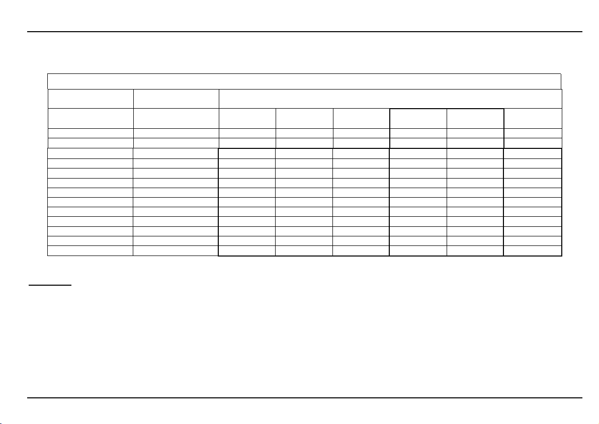
The following table shows the relation between clock frequency, delay time and number of stages for some typical BBD
circuits.
Relation between clock frequency [kHz] and delay time [ms]
BBD circuit
number of stages
clock frequency
(clock input socket)
[kHz] [kHz] 128 256 512
1 0,5 128,00 256,00 512,00 1024,00 2048,00 4096,00
2 1 64,00 128,00 256,00 512,00 1024,00 2048,00
5 2,5 25,60 51,20 102,40 204,80 409,60 819,20
10 5 12,80 25,60 51,20 102,40 204,80 409,60
20 10 6,40 12,80 25,60
50 25 2,56 5,12 10,24
100 50 1,28 2,56 5,12
200 100 0,64 1,28 2,56
300 150 0,43 0,85 1,71 (*)
400 200 0,32 0,64 1,28 (*)
500 250 0,26 0,51 1,02 2,05 4,10 8,19
(*) The max. clock frequency is 100 kHz only for MN3004 and MN3007 (in contrast to 200kHz for MN3204 and MN3207)
BBD clock frequency
(= 1/2 clock input)
MN3006
MN3206
MN3009
MN3209
MN3004 (*)
MN3204
MN3007 (*)
MN/BL3207
1024 2048
51,20 102,40
20,48 40,96
10,24 20,48
5,12 10,24
3,41 (*)
2,56 (*)
MN/BL3208
MN3008
6,83 13,65
5,12 10,24
MN3005
MN3205
204,80
4096
81,92
40,96
20,48
Remarks:
The standard versions of the A-188-1 with 1024 and 2048 stages are marked with bold characters.
The grey italic characters indicate parameters out of the data sheet specifications (e.g. clock frequencies below 10kHz for
all BBD devices, and clock frequencies beyond 100kHz or 200kHz for certain BBD devices). But parameters out of spec
may be available with the A-188-1. As the BBD devices cannot be damaged if they are operated with frequencies out of
spec we decided to allow such frequencies with the A-188-1 to obtain special audio effects – especially for clock
frequencies below 10kHz. But the regular behaviour is no longer guaranteed (especially increasing voltage losses at lower
frequencies). As the clock frequency falls below ~ 20 khz the clock signal itself will become audible. This clock noise can be
used as unusual audio source or it can be filtered out with an external low pass filter.
3
Page 4
DOEPFER
DOEPFER System A-100 BBD Module A-188-1
DOEPFERDOEPFER
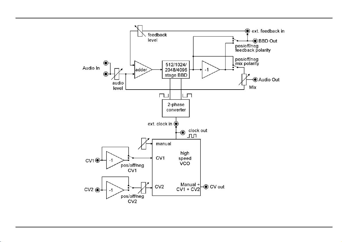
Fig. 3: A-188-1 module scheme
4
Page 5

DOEPFER
DOEPFER System A-100 BBD Module A-188-1
DOEPFERDOEPFER
Fig. 3 shows the internal details of the module A-188-1: the
upper part is the actual BBD section, the lower part the high
speed VCO (HSVCO).
The HSVCO generates the clock signal that is required to
drive the BBD. It has available a manual control and two CV
inputs (CV1 without attenuator, CV2 with attenuator). For
both CV inputs three-position polarity switches (negative /
off / positive) are available. The position of these switches
defines if a positive going CV has positive, none or negative
effect on the clock frequency. CV1 has a sensitivity of
approximately 1V/octave. The HSVCO has a CV out
available that corresponds to the sum of all CVs (manual,
CV1 and CV2). It's main purpose is to control the CV input
of one or two external low pass filters that can be used as
anti-aliasing filter and clock filter. If desired one low pass
filter can be used behind the audio output to suppress the
clock noise when the clock frequency falls below ~20 khz.
Another filter can be used at the audio input to reduce the
max. frequency of the incoming audio signal, consequently
reducing aliasing artefacts. As the CV output reflects the
clock frequency (affected by the manual control, CV1 and
CV2) the external filters automatically follow the clock
frequency of the BBD module. The higher the slope of the
external filter (e.g. 12/24/48 dB/octave) the better is the
clock suppression. The HSVCO features a clock output that
can be used e.g. to synchronize two A-188-1 (i.e. both A188-1 use the same clock source) or as high speed clock for
other applications (e.g. graphic VCO, switched capacitor
filter).
The clock output of the HSVCO is normalled to the clock
input of the BBD section. The clock input makes it possible
to control the BBD by an external clock source (e.g. another
A-188-1 or any other clock signal in the required frequency
range). For all clock signals from and to the A-188-1 only
short patch cables should be used, as long cables function
as low pass filters for signals above 20kHz.
A two-phase converter generates the two opposite clock
signals that are required to drive the BBD circuits.
The audio input of the BBD module is equipped with an
attenuator that enables to reduce the input level to avoid
distortion. The audio input signal behind the attenuator is
mixed with the feedback signal (details below) and fed to the
audio input of the BBD circuit. The audio output of the BBD
is processed by an inverter to have both the normal and the
inverted BBD output available. The reason for this feature is
that the polarity is crucial for both the output mixing (BBD +
original) and the feedback behaviour of the module. The
normal output of the BBD and the inverted output are fed to
the terminals of two three-position polarity switches
(negative / off / positive) for mixing polarity and feedback
polarity.
The output mixer is used to mix the original signal with the
normal or inverted BBD signal. The position of the mix
polarity switch defines if the normal, none or the inverted
BBD output is mixed with the original audio signal.
5
Page 6

DOEPFER
DOEPFER System A-100 BBD Module A-188-1
DOEPFERDOEPFER
The following sketch shows the effect of normal/inverted
mixing by means of a simple sawtooth signal as audio input.
Fig. 4: positive/negative mixing of original and BBD signal
The center terminal of the feedback polarity switch is
connected to the BBD output socket. Pay attention that the
polarity of this output is affected by the position of the
feedback polarity switch (especially there is no signal at the
output socket if the switch is in the center position) ! The
feedback input is normalled to the output socket. The
combination of these two sockets allows to process the
feedback loop with external modules (e.g. a VCA or a VC
polarizer for voltage controlled feedback, or other modules
like filter, phaser, frequency shifter, waveshaper, wave
multiplier, ring modulator or another BBD module for special
voltage controlled feedback effects)
The polarity of the feedback signal leads to clearly audible
different sounds as different frequencies are emphasized or
attenuated for positive or negative feedback.
The feedback can be increased up to self-oscillation. In
contrast to other feedbacks (e.g. filters, phasers) the result
in the self-oscillation state depends upon the "audio history"
(i.e. the contents of the BBD when the self-oscillation is
triggered). The reason is that there is not only one possible
stable self-resonant state for the BBD. Any cyclic waveform
"stored" in the BBD is able to resonate provided that the
feedback maintains the waveform. One can try this out e.g.
with different audio signals (e.g. digital noise and VCO
sawtooth) as audio input before self-oscillation is triggered
(e.g. by switching the feedback polarity switch from center
position to positive or negative position).
Different BBD circuits (128/256/512 ... 4096 stages)
influence a lot of sound parameters. Of course the delay
time range and consequently the basic sound, but even the
feedback behaviour (both the self-oscillation and the
"smoothness" of the feedback), the distortion behaviour and
the output level. It is hard to say which is the "best" solution.
It depends upon the desired sound "bending". For typical
analog delay sound BBDs with more stages are the better
solution. But for "oppressive" flanging sounds caused by
short delays or for Karplus-Strong synthesis shorter BBDs
are recommended.
6
Page 7
DOEPFER
DOEPFER System A-100 BBD Module A-188-1
DOEPFERDOEPFER
3. Overview
%
6
&
7
/
(
8
)
9
1
!
2
"
3
§a
4
§b
5
$
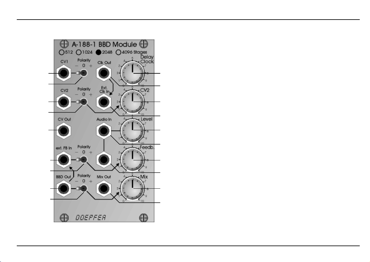
Controls:
1 Delay Clock : manual delay control
2 CV2: attenuator for CV2
3 Level: audio input attenuator
4 Feedback: feedback level control
5 Mix: mix control (original/BBD)
6 Polarity: CV1 polarity
7 Polarity: CV2 polarity
Polarity: feedback/BBD Out polarity
8
Polarity: mix polarity
9
In- / Outputs:
Clk Out: clock output HSVCO
!
Ext. Clk In: BBD clock input
"
(normalled to Clock Out
§a Audio In: audio input (connected to §b)
b Audio In: audio input (connected to §a)
§
$ Mix Out: mixed output
% CV1: CV1 input HSVCO
& CV2: CV2 input HSVCO
/ CV Out: CV output HSVCO
( Ext.FB In: external feedback input
(normalled to BBD Out
BBD Out: BBD output
)
(affected by polarity switch
)
!
)
)
8)
Fig.5: A-188-1 front panel
Attention: the front panel markings are wrong concerning
the BBD Output and the feedback polarity switch. Please
refer to the scheme on page 4.
7
Page 8

DOEPFER
DOEPFER System A-100 BBD Module A-188-1
DOEPFERDOEPFER
4. Controls and In- / Outputs
4.1. High Speed VCO Section
1 Delay Clock : manual delay control
CV1: CV1 input HSVCO
%
6 Polarity: CV1 polarity
& CV2: CV2 input HSVCO
7 Polarity: CV2 polarity
CV: attenuator for CV2
2
This group of elements is responsible for the clock
frequency generated by the high speed VCO (HSVCO).
knob 1 Delay Clock is used to adjust the clock manually.
Two CV inputs (% CV1, & CV2) are available to control the
clock by external control voltages (e.g. LFO, envelope
follower, random, ADSR, keyboard CV, sequencer,
theremin, ribbon controller, foot controller, Midi-to-CV,
shepard generator ...). The sensitivity of CV1 is
approximately +/– 1V/oct according to the position of the
CV1 polarity switch 6. The diagram on the right side shows
the connection between CV1 and clock frequency. The
straight line represents the perfect 1V/oct graph. The slightly
bended curve is the real behaviour of the HSVCO. If an
absolutely "perfect" 1V/oct control is required an external
precision HSVCO or a VCO with PLL has to be used.
Fig 6: relation between CV1 and Clock Frequency
Both CV inputs are equipped with polarity switches (6, 7).
According to the position of these switches the effect of the
corresponding CV is positive (i.e. increasing CV increases
the clock frequency), off, or negative (i.e. increasing CV
decreases the clock frequency).
Clk Out: clock output HSVCO
!
This is the clock output of the HSVCO. It is internally
connected to the clock input of the BBD section. The
waveform is rectangle with about ± 3V level. The rectangle
slopes flatten with increasing frequency and the waveform
turns more and more into triangle. Even the load on the
output has influence to the waveform and level.
8
Page 9

DOEPFER
DOEPFER System A-100 BBD Module A-188-1
DOEPFERDOEPFER
Consequently for all clock patches from and to the A-188-1
only short patch cables (~ 30 cm) should be used as long
cables function as low pass filters for signals above 20kHz.
The max. frequency at this output depends upon the BBD
used in the module and is related to the max. clock
frequency of the BBD in question (pls. refer to the table on
page 3). It is about 250 kHz for BBDs with 2048 and 4096
stages and about 450kHz for BBDs with 1024 stages and
less (i.e. a bit more than the max. clock frequency of the
specs in the data sheet). If the BBD circuit is changed the
max. frequency has to be re-adjusted with a trimming
potentiometer on the pc board of the module (frequency
offset). For details please refer to the appendix of this
manual.
/ CV Out: CV output HSVCO
This CV output indicates the clock frequency at output
and is nothing but the sum of all CV inputs (manual, CV1
and CV2). The main purpose of this output is to control the
CV input of one or two external low pass filters that can be
used as anti-aliasing filter and clock filter. If desired one low
pass filter can be used behind the audio output to suppress
the clock noise when the clock frequency falls below ~20
khz. Another filter can be used at the audio input to reduce
the max. frequency of the incoming audio signal,
consequently reducing aliasing artefacts. As the CV output
reflects the clock frequency (affected by the manual control,
CV1 and CV2) the external filters automatically follow the
clock frequency of the BBD module. The higher the slope of
the external filter (e.g. 12/24/48 dB/octave) the better is the
!
clock suppression. But the CV output can be used for other
applications as well, e.g. controlling parameters of the
feedback loop like feedback amount/polarity (CV of a VCA
or VC polarizer used in the feedback loop), filter frequency
(CV of a VCF used in the feedback loop), phase shift (CV of
a VC phaser used in the feedback loop).
9
Page 10

DOEPFER
DOEPFER System A-100 BBD Module A-188-1
DOEPFERDOEPFER
4.2. BBD Section
Ext. Clk In: BBD clock input
"
This is the clock input of the BBD section and is internally
connected to the clock output ! of the HSVCO section (i.e.
it is normalled to the Clock Out socket !). If an external
clock source is used the clock output of this source is
patched to socket ". In this case the internal connection to
the HSVCO is interrupted. The suitable clock frequencies
depend upon the BBD used in the module (pls. refer to the
table on page 3). The required level for the clock signal is
0/+5V (levels up to +12V cause no problems). This socket
can be used e.g. to synchronize two A-188-1 modules (i.e.
using one HSVCO for both modules).
a/b Audio In: audio input
§
3 Level: audio input attenuator
Sockets §a and §b are the audio input with the assigned
attenuator 3. The two sockets are internally connected
(miniature multiple). The second socket can be used to
forward the audio input signal to other modules (e.g. to a
VCA or VC polarizer or VC mixer for voltage controlled
mixing functions). Feed the audio signal that has to be
processed with the BBD effect into socket §a or §b.
Adjust the Level control 3 so that the output signal does not
distort - unless you want to obtain distortion. For normal A100 levels (e.g. VCO A-110) distortion appears at about
three o'clock position of control 3 but the distortion
behaviour depends also upon the BBD circuit used in the
module.
) BBD Out: BBD output
Socket ) is the "raw" BBD output (i.e. not mixed, not
filtered). Pay attention that it is affected by polarity switch
).
8
Remark: The front panel markings of the first two
productions series are wrong concerning the BBD Output
and the feedback polarity switch. Please refer to the scheme
on page 4.
The BBD output can be used e.g. for voltage controlled
mixing functions (i.e. if the original signal and the BBD
signal are mixed externally with VCAs or VC polarizers or a
VC mixer).
$ Mix Out: mixed output
Mix: mix control (original/BBD)
5
9 Polarity: mix polarity
This group of elements is responsible for the mixed output
appearing at socket $ Mix Out. In the left/ccw position of
knob 5 Mix the original signal appears at socket $. In the
right/cw position of knob 5 the pure BBD signal appears at
socket $. In the intermediate positions of knob 5 a mix of
these two signals appear at the output socket. For a
standard flanger effect e.g. the center position is used.
10
Page 11

DOEPFER
DOEPFER System A-100 BBD Module A-188-1
DOEPFERDOEPFER
The position of the polarity switch 9 defines if the normal or
the inverted BBD signal is mixed to the original signal
(please refer to page 6 concerning this function). Especially
for short delay times the position of this switch leads to
clearly audible different sounds. In the middle position of the
switch the BBD share of the mixed signal is off and only the
original signal is heard. Consequently the switch can be
used to turn on/off the BBD effect at the mix output $.
Ext.FB In: external feedback input
(
4 Feedback: feedback level control
Polarity: feedback/BBD Out polarity
8
This group of elements is responsible for the feedback
functions of the module. Socket ( Ext.FB In is the input of
the feedback loop and is normalled to socket ) BBD Out. If
an external module is used to control the feedback loop
(e.g. a VCA or VC polarizer) the module has to be inserted
between socket ) BBD Out and socket ( Ext.FB In. The
polarity switch 8 controls the polarity of the signal appearing
at the socket ) BBD Out and consequently the polarity of
the feedback signal. In the center position of switch 8 the
signal at socket ) BBD Out is off and no feedback is active.
Consequently the switch can be used to turn on/off the
feedback effect. The polarity of the feedback signal leads to
clearly audible different sounds at short delay times. For
longer delay times ("analog delay" application) the sound
differences are much smaller (for details please refer to
page 6).
Knob 4 Feedback adjusts the feedback level. In the left/ccw
position of the knob no feedback (or resonance/emphasis) is
added. As the knob is turned right/clockwise feedback
occurs. In the fully right/cw position the module goes into
self-oscillation. As already mentioned in chapter 2 the result
in the self-oscillation state depends upon the "audio history"
(for details please refer to page 6). Both the self-oscillation
behaviour and the "smoothness" of the feedback also
depend upon the BBD circuit used in the module (128/256
... 4096 stages).
11
Page 12

DOEPFER
DOEPFER System A-100 BBD Module A-188-1
DOEPFERDOEPFER
5. User Examples
Standard Flanger Patch
Suitable control voltage sources are LFO (A-145 as shown
in the example, A-146, A-147, A-143-3), random voltage (A118, A-149-1), envelope (A-140, A-141, A-142, A-143-1, A143-2), S&H (A-148, A-152), sequencer (A-155), theremin
(A-178), ribbon controller (A-198).
Voltage Controlled Feedback
Feedback is processed by an external voltage controlled
polarizer (A-133) to obtain voltage controlled feedback.
Instead of the polarizer even a VCA can be used. But with a
VCA only positive or negative feedback is possible.
12
Page 13

DOEPFER
DOEPFER System A-100 BBD Module A-188-1
DOEPFERDOEPFER
"Enveloped" BBD
Control voltage for the A-188-1 is generated by the
envelope of the processed audio signal. Try positive and
negative setting of the CV2 polarity switch and different CV2
levels !
Filtered Feedback
The feedback loop is processed by an external filter. The
example shows an A-124 Wasp filter in the feedback loop.
But any low pass, high pass, band pass or notch filter (even
multiple filters like A-104 or A-127), phasers (A-101-3, A-
125) or frequency shifter (A-126) can be used.
Especially for the Karplus/Strong Synthesis (see below) a
low pass filter is useful in the feedback loop to simulate the
natural behaviour of a plugged string by damping higher
frequencies in the decay phase.
13
Page 14
DOEPFER
DOEPFER System A-100 BBD Module A-188-1
DOEPFERDOEPFER
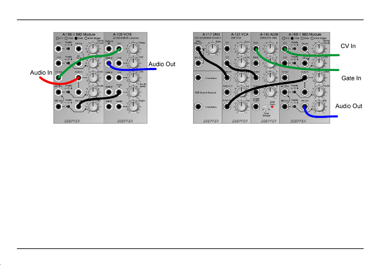
Clock Filter
The BBD audio output is filtered with a low pass (e.g. A-
108). The frequency of the low pass filter follows the BBD
clock frequency as the CV output of the module A-188-1 is
used to control the frequency of the low pass filter. A second
filter can be used at the audio input of the A-188-1 to limit
the frequency range of the processed audio input signal.
Basic Karplus/Strong Synthesis Patch
CV and gate are delivered e.g. by a sequencer, ribbon
controller, Midi-to-CV interface or Theremin. The time
parameters of the envelope generator (ADSR A-140) and
the feedback settings of the A-188-1 define the sound –
especially the decay time. If voltage controlled envelope
generator (e.g. A-141) and a VCA or VC polarizer are used
to process the feedback loop all parameters are voltage
controlled. Even other sound sources (6 oscillators or 2
oscillators of the A-117, noise signal of an A-118, or VCO,
or only short "click" of the ADSR) can be used. For more
realistic Karplus/Strong applications a filter in the feedback
loop can be used (see previous page).
14
Page 15

DOEPFER
DOEPFER System A-100 BBD Module A-188-1
DOEPFERDOEPFER
Karplus/Strong Random melody patch (A149/1)
This patch shows another example for the Karplus/Strong
synthesis. The LFO A-145 is used as clock oscillator but any
other clock source could be used as well. The rectangle
output is connected to the clock input of the Quantized /
Stored Random Voltages module A-149-1 (upper or lower
section may be used) and to the gate input of the envelope
generator A-140. One of the quantized or stored CV outputs
of the A-149-1 is patched to the CV1 input of the A-188-1.
The rest of the patch is the same as the basic
Karplus/Strong Synthesis Patch (only the "6 oscillators"
output of the A-117 is used instead of the digital noise
output in the basic patch).
The patch generates a random melody. The tempo is
defined by the LFO rate, the tone range by the "N" settings
of the A-149-1 (Manual "N" and possibly CV "N"). Additional
modules can be used e.g. to modulate "N" of the A-149-1 or
the decay time of a voltage controlled envelope generator
(e.g. A-141 or A-142 instead of the A-140) by another
random voltage of the A-149-1.
15
 Loading...