

Page 1
doepfer
A-185
Bus Access
Gate
In
Gate
Out
CV
In
System A - 100
1. Introduction
Module A-185 (Bus Access) enables the user to have
access
A-100. This is an active connection, with booster
amplification (see fig. 1), to maintain correct levels for
CV and gate signals, and to avoid the signal losses
and consequent problems that a simple passive linkup might cause.
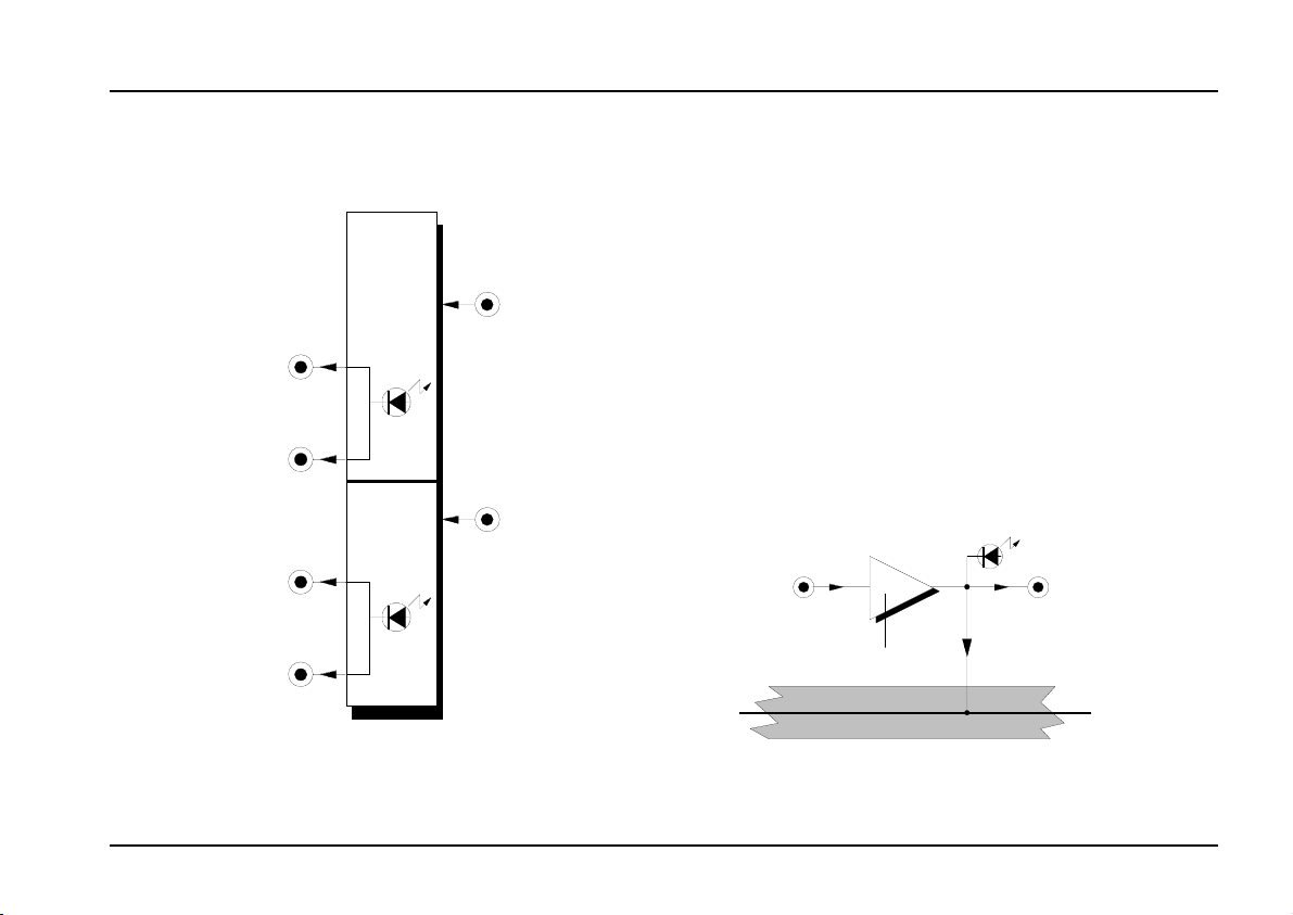
The gate and CV inputs on the A-185 are used to
patch external gate and/or CV signals into the
A-100 system bus; while the internal system bus CV
and gate signals are available at the gate and CV
outputs of the A-185. Two LEDs provide a visual
indication of the signals.
to the
Bus Access A-185
internal system bus
of the System
CV
Out
CV In
(Frontplatt e)
Aufholverstärker
Systembus
CV Out
(Frontplatt e)
CV- Leitung
fig. 1: patching an external CV into the system bus
1
Page 2
A-185
Bus Access
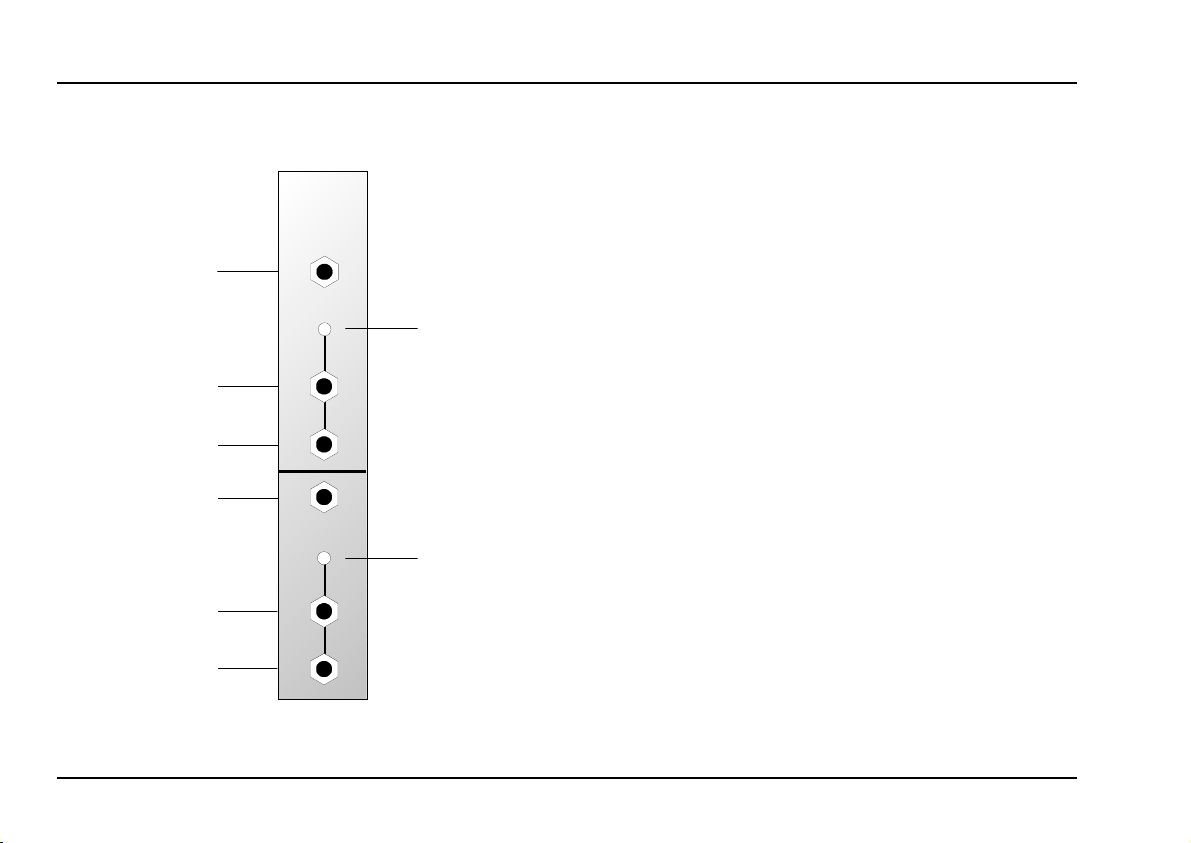
2. Overview
A-185
BUS ACCESS
Gate
In
Contr.
System A - 100
➀
doepfer
Controls:
Contr. : system bus gate indicator LED
1
2
In / Outputs:
: system bus CV indicator LED
Contr.
Gate
Out
Gate
Out
CV
In
Contr.
➁
CV
2
Out
CV
Out
Gate In : input for external gate signal
!
Gate Out
", §
§ CV In : input for external CV signal
CV Out
$, %
:outputs (internally linked) for whatever
gate signal is present on the internal
system bus
: outputs (internally linked) for whatever
CV signal is present on the internal
system bus
Page 3

doepfer
System A - 100
Bus Access A-185
3. Controls
1 Contr.
LED indicator 1 shows the state of the gate signal on
the system bus.
2 Contr.
LED indicator 2 gives a visual indication of the CV
present on the system bus.
4. In / Outputs
! Gate In
Use
gate input
gnals.
" Gate Out • § Gate Out
The two internally linked gate outputs " and § provide access to any gate signal present in the internal
system bus.
$ CV In
Use
CV input $
% CV Out • & CV Out
The two internally linked CV outputs % and & provide
access to any CV signal present in the internal system
bus.
! for patching in
for patching in
external CV signals
external gate si-
.
3
Page 4

A-185
Bus Access
System A - 100
doepfer
5. User examples
Creating a common system bus for an
A-100 with more than one 6U rack system
If your System A-100 fits into just one 6U rack, and you
want to connect up the upper and lower system busses so that their CV and gate signals are linked, you
can usually just connect them internally with the optional A-100BC cable (see the A-100 main system manual, chapter 3, page 10).
But if you want to connect the CV and gate signals on
two or more 6U racks, then module A-185 comes
into its own.
Fig. 2 (see next page) shows the basic connection
plan.
A Important note concerning the A-190:
If, as in fig.1, you connect up the signals from an
A-190 MIDI interface to the system bus via an
A-185, you must disconnect the A-190’s
internal connection from the system bus
(see the A-190 manual, p. 4).
Compensation for signal losses
There are also times when an A-185 is useful even
with just one 6U rack. Particularly if you’re running
more than two VCOs from the same common system bus
for the keyboard scaling to go slightly out, causing high
notes to be annoyingly out of tune. The booster amplifier if the A-185 will avoid any such problems.
Losses of the gate voltage normally cause no problems as low threshold values (~2...3 V) are required
to trigger gate inputs (e.g. ADSR A-140). However for
pitch control voltages even a few millivolts will cause
an audible detuning.
When feeding external pitch CVs to the A-100 (e.g.
from an external MIDI-to-CV interface or from one our
sequencers MAQ16/3, Schaltwerk or Regelwerk) the
usage of an A-185 is recommended - especially if
more than one VCO is driven by the external CV.
Even for voltage losses of other pitch processing
modules (e.g. the slew limiters A-170 or A-171) the
A-185 may help in case of detuning problems.
, the internal CV voltage can drop sufficiently
4
Page 5

doepfer
A-190
MCVS
MIDI-CV/SYNC INTERF.
Group
Menu
Inc./+
Dec./-
Group
Perform. Config.
Ø
×
Channel
CV 1
LFO Frq.
Clock
Glide
Offset
Assign
Scale
Arpeg.
Retrig.
Bend W.
CV 2
MIDI
Thru
MIDI
In
Clock
Reset
Gate
CV 1
CV 2
A-185
BUS ACCESS
Gate
In
Contr.
Gate
Out
Gate
Out
CV
In
Contr.
CV
Out
CV
Out
System A - 100
A-185
BUS ACCESS
Gate
In
Contr.
Gate
Out
Gate
Out
CV
In
Contr.
CV
Out
CV
Out
Bus Access A-185
A-185
BUS ACCESS
Gate
In
Contr.
Gate
Out
Gate
Out
CV
In
Contr.
CV
Out
CV
Out
Frame 1 Frame 2 Frame 3
Rahmen 1 Rahmen 2 Rahmen 3
: Connecting the system busses on a multiple-rack A-100 system
fig. 2
5
Page 6

A-185
Bus Access
System A - 100
doepfer
6. Appendix
Module A-185 has two internal jumpers on its circuit
board, which are factory-set to send external CV and
gate signals to the system bus (see fig. 1).
By re-aligning these jumpers, you can convert the
A-185 so that it doesn’t take gate and CV signals from
the input sockets, but simply ‘reads’ them from the
system bus, and sends them out to the front panel CV
and gate output sockets. In this “read-only” mode, the
input sockets are disconnected from the system bus
(see fig. 3).
CV In
(front panel)
refresh amplifier
A-100 bus
CV Out
(front panel)
CV
In practice, there aren’t admittedly going to be a lot of
occasions when this is required, so we won’t go into
any more detail here.
H
As delivered from the factory, the jumpers
are set so that the module sends CV and
gate signals to the system bus.
fig. 3: example of “read-only” mode with CVs
6
Page 7

doepfer
7. Patch-Sheet
System A - 100
Bus Access A-185
The following diagrams of the module can help
you recall your own Patches. They’re designed so
that a complete 19” rack of modules will fit onto an
A4 sheet of paper.
Photocopy this page, and cut out the pictures of
this and your other modules. You can then stick
them onto another piece of paper, and create a
diagram of your own system.
Make multiple copies of your composite diagram,
and use them for remembering good patches and
set-ups.
P Draw in patchleads with colored pens.
A-185
BUS ACCESS
Gate
In
Contr.
Gate
Out
Gate
Out
CV
In
Contr.
CV
Out
CV
Out
A-185
BUS ACCESS
Gate
In
Contr.
Gate
Out
Gate
Out
CV
In
Contr.
CV
Out
CV
Out
A-185
BUS ACCESS
Gate
In
Contr.
Gate
Out
Gate
Out
CV
In
Contr.
CV
Out
CV
Out
7
Page 8

A-185
Bus Access
System A - 100
doepfer
8
 Loading...