

Page 1

doepfer
A-179
Light Ctr. Volt. Source
ext.
Sensor
Inv. CV
Out
CV
Out
Gate Out
Light
Sensor
+
Offset
-
+
-
Threshold
System A - 100
1. Introduction
Module A-179 (Light-Controlled Voltage Source)
produces a
upon the illumination intensity of a light sensor
(photo resistor). One can use ”active” illumination (e.g.
flashlight, mini laser) or ”passive” illumination
(darkening by making a shadow, e.g. with your hand).
The resulting control voltage is available in
and inverted form. You can use these control voltages
in any modulation or control process, and thus have
access to an extra system of real-time synthesis control.
You use the Offset control to set the
of the control voltage output. Two LEDs give a visual
indication of the voltages produced.
The module also produces a gate signal at the
output: the signal goes "high" as soon as a voltage is
sensed which is above the threshold set with the
Threshold control
of the presence of a gate signal.
Light Ctr. Volt. Source
variable control voltage
. An LED gives a visual indication
A-179
which depends
normal
null point
(zero)
gate
Instead of the internal sensor an external remote
light sensor
may be used.
1
Page 2
A-179
Light Ctr. Volt. Source
System A - 100
doepfer
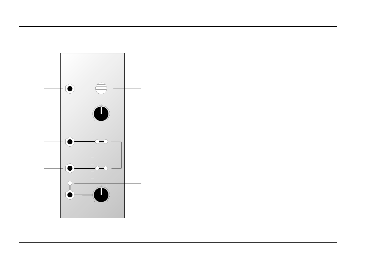
2. LCV - Overview
A-179
Light Ctr. Volt. Source
ext. Sensor
Inv. CV
Out
CV
Out
Gate Out
Light Sensor
Threshold
LCV
0
Offset
0
Controls:
Light Sensor: Light sensitive element (photo
1
resistor)
Offset
2
➀
3 LEDs : LEDs to give a visual indication of the
LED : LED to give a visual indication of the
4
➁
Threshold : Control for setting the gate threshold
10
5
: Control for setting the null (zero)
point
voltages present at outputs " and
presence of a gate signal at output $
§
In- / Outputs:
+-
➂
+-
➃
ext. Sensor
!
CV Out : CV output (normal)
"
Inv. CV Out
§
$ Gate Out : Gate output
: Input for external sensor (normalled
jack socket)
: CV output (inverted)
➄
10
2
Page 3
doepfer
System A - 100
Light Ctr. Volt. Source
A-179
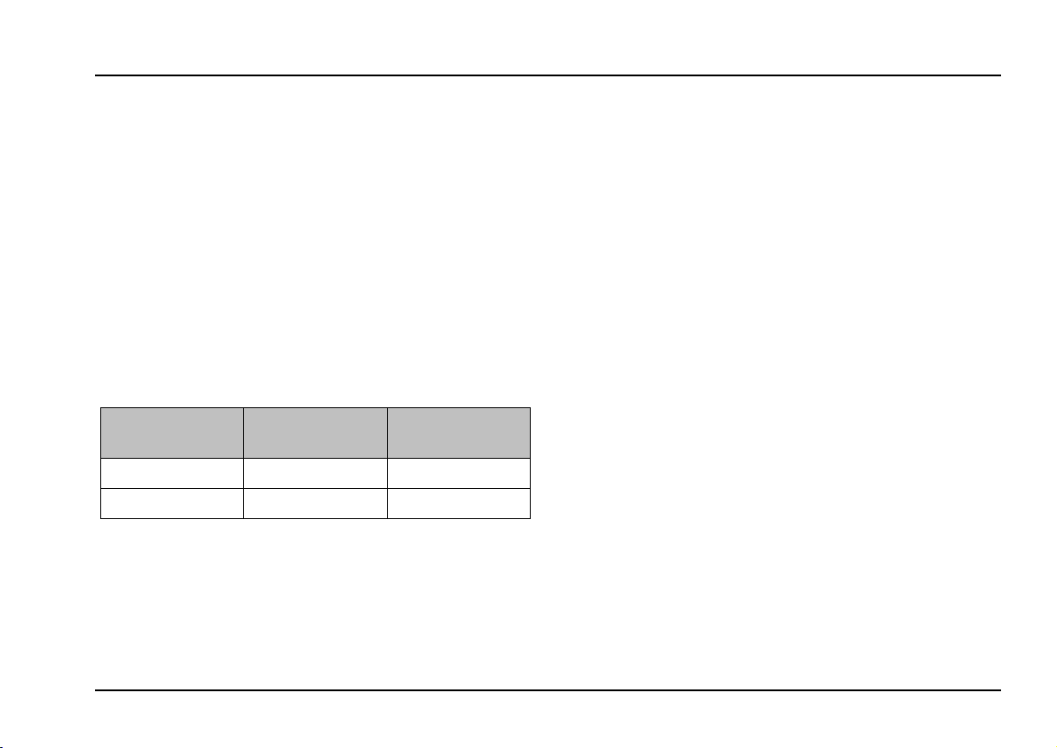
3. Controls
1 Light Sensor
Different illumination intensities hitting the built-in
sensor 1 (photo resistor) result in varying control
voltages at CV outputs " and § .
One can use ”active” illumination (e.g. flashlight, laser
pointer, spotlight) or ”passive” illumination (covering/
shading the sensor from ambient light with hand or
body).
The connection between illumination and control
voltage is as follows:
Illumination
intensity
low (dark) low high
high (bright) high low
Instead of the built-in sensor an external photo resistor
may be connected to the normalled jack socket !. In
this case the internal sensor is turned off and the
external sensor is used to control the output voltages.
Any photo resistor (e.g. LDR07) may be used as the
external sensor. If a shielded cable is used the cable
Voltage at
CV output
§
Voltage at
CV output
light
"
length is largely irrelevant - we tried up to 20m without
problems.
2 Offset
Control 2 is used to adjust the
control voltage at the outputs " and § is about 0 V in
the neutral state. The neutral state depends upon how
the A-179 is being used (e.g. in the ”passive” mode the
neutral state corresponds to having the sensor fully
illuminated and uncovered).
null point
, so that the
3 LEDs
The LEDs 3 indicate the state of the voltages at CV
outputs " and §.
4 LED
LED 4 shows the presence of a gate signal at gate
output $.
5 Threshold
Using control 5 you set a
output § , above which a gate signal will be produced
at output $.
threshold
voltage for the CV
3
Page 4

A-179
Light Ctr. Volt. Source
System A - 100
doepfer
4. In / Outputs
! ext. Sensor
If one connects an
resistor LDR07) to the normalled jack socket ! the
internal sensor is turned off and the illumination of the
external sensor controls the output voltages.
external sensor
" Inv. CV Out • § CV Out
CV output " puts out the inverted control voltage, and
output § the normal control voltage.
CV output § generates a decreasing voltage, and
output " an increasing voltage when the illumination
decreases (i.e. by covering the sensor).
$ Gate Out
Socket $ puts out a gate signal whenever the control
voltage at output § is greater than the threshold set
with control 5. This gate signal can be used e.g. as a
noise-gate or as a source of manually-triggered gates
for other modules (see user examples).
1 (e.g. photo
5. User examples
Module A-179 is another controller that enables
changing sound parameters in
Theremin A-178 or Foot Controller A-177.
Varying the illumination can be used for all sorts of
control or modulation. Here are some examples:
• VCO pitch control
• VCA gain
• VCF cut-off frequency
• VCF resonance (with the A-121, 122 or 123)
• VC-LFO frequency
LFO modulation depth
•
Panning (A-134)
•
Morphing (A-144 + A-135)
•
Time parameters of a VC-ADSR or VC-Decay
•
Start/Stop
•
• Clock speed
real time
like the
4
Page 5
doepfer
System A - 100
Light Ctr. Volt. Source
A-179
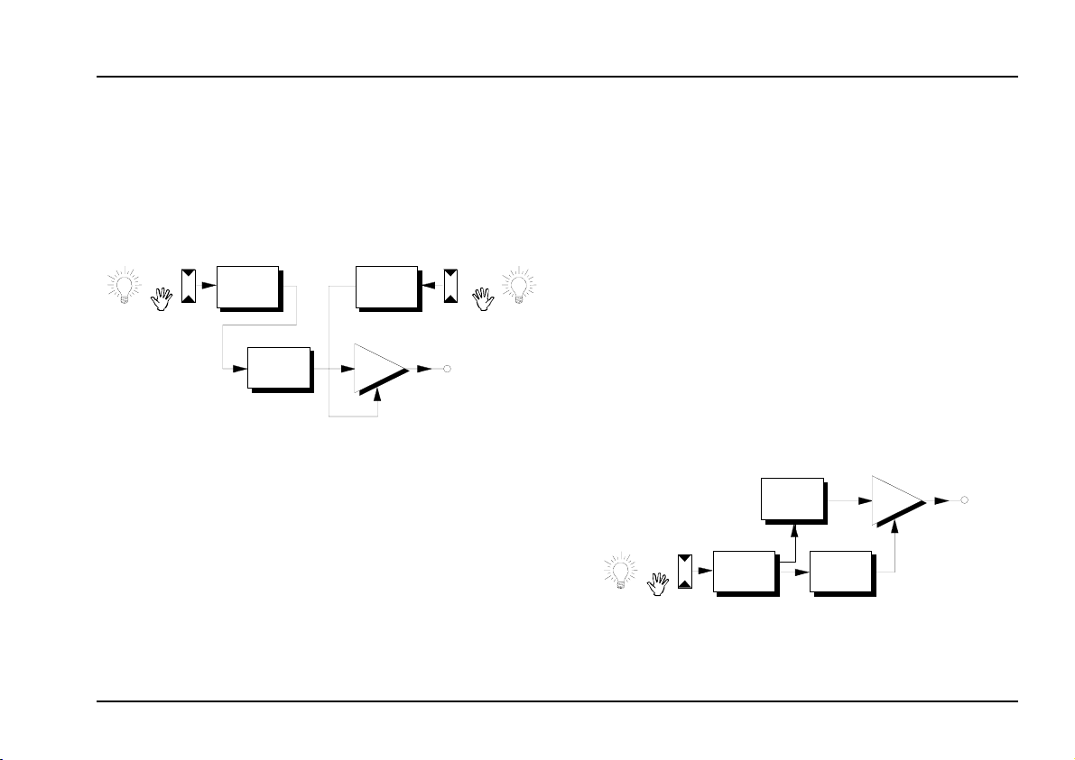
Light controlled "Theremin"
Fig. 1 shows a ”light controlled Theremin”. In contrast
to the Theremin the pitch (VCO) and loudness (VCA)
parameters are not controlled by the distance to the
antennas but by the illumination of the light sensors of
two A-179s. For details concerning the Theremin
please look at the A-178 user’s guide.
A-179
cv
VCO
Fig. 1: “light controlled Theremin"
If the light source is located a few meters away from
the sensors it's possible to control them with whole
body movements (e.g. controlling A-179s by dancing).
Module A-179 allows the creation of "environment-
controlled sounds
” for special performances, i.e.
sound generation (pitch, timbre, loudness, panning,
clock speed ...) responding to illumination changes
caused by the movement of people or objects.
cv
A-179
VCA
Using the gate function
The gate function in the A-179 gives you the facility to
have remote switching of events in real time, simply
by changing the illumination in one of the ways
described on the previous pages:
Start/Stop (e.g. of a sequencer)
•
• "One-Shot" (ADSR-triggered sound event)
• Switching filter types or VCO waveforms
• Advancing Sequential Switch A-151 to next step
Another example is an audio gate, using the gate
signal to switch a VCA on and off, either directly or via
an ADSR or slew limiter (Fig. 2). Whenever the signal
is below a certain voltage, the VCA simply shuts down.
VCO
CV
A-179
Gate
ADSR
Fig. 2: User example for the audio gate function
VCA
5
Page 6
A-179
Light Ctr. Volt. Source
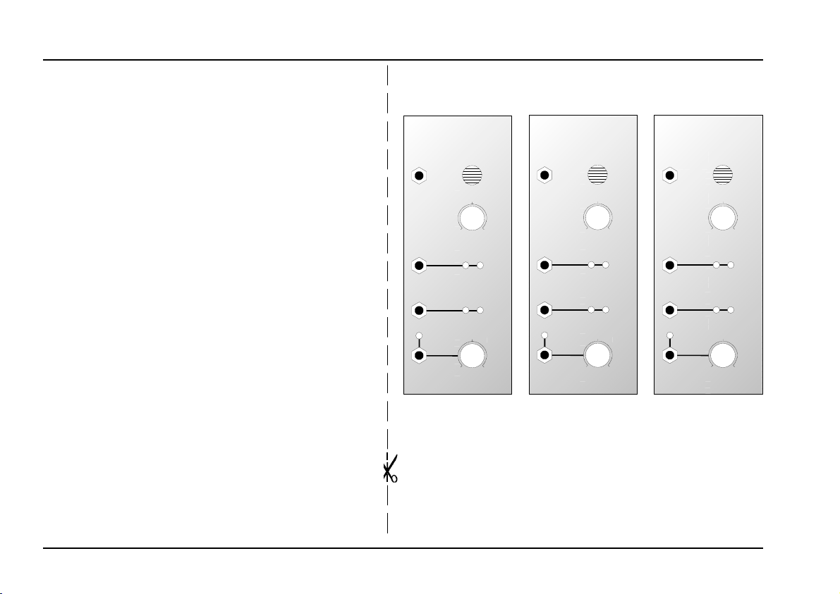
6. Patch-Sheet
System A - 100
doepfer
The following diagrams of the module can help you
recall your own Patches. They’re designed so that
a complete 19” rack of modules will fit onto an A4
sheet of paper.
Photocopy this page, and cut out the pictures of this
and your other modules. You can then stick them
onto another piece of paper, and create a diagram
of your own system.
Make multiple copies of your composite diagram,
and use them for remembering good patches and
set-ups.
P • Draw in patchleads with colored pens.
• Draw or write control settings in the
little white circles.
A-179
Light Ctr. Volt. Source
ext. Sensor
Inv. CV
Out
CV
Out
Gate Out
LCV
Light Sensor
0
Offset
+-
+-
0
Threshold
A-179
Light Ctr. Volt. Source
ext. Sensor
10
10
Inv. CV
Out
CV
Out
Gate Out
LCV
Light Sensor
0
Offset
+-
+-
0
Threshold
10
10
A-179
Light Ctr. Volt. Source
ext. S ensor
Inv. CV
Out
CV
Out
Gate Out
LCV
Light Sensor
0
Offset
+-
+-
0
Threshold
10
10
6
 Loading...