

Page 1
doepfer
Contr. Volt. Source
CV 1
CV 1
Fine
CV 2
System A - 100
1. Introduction
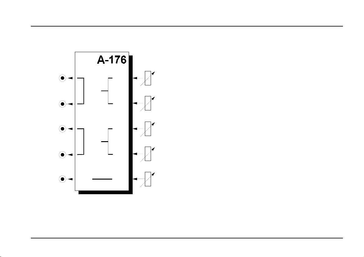
Module A-176 (Control Voltage Source) provides
three
voltage sources
is required.
The top two voltage sources (CV 1 and CV 2) have
controls for
output; the third source (CV 3) just has the one control.
The range of the voltages output can be preset, either
to
0 to +5 V
likely requirements. There is a jumper on the circuit
board for each of the three voltage sources.
Control Voltage Source A-176
, to use wherever an extra CV
coarse
or to
and
-2.5 V to +2.5 V
control of the voltage
fine
depending on your
CV 3
CV 2
Fine
CV 3
A typical use for the module would be to provide fine
as well as coarse tuning for an A-110 standard VCO,
(which, unlike the A-111, only has one tune control),
See chapter 5, user examples.
In general, this module will be useful whenever you
need a manually controllable CV on a module which
doesn’t itself have a built-in control.
1
Page 2
A-176
Control Voltage Source
System A - 100
doepfer
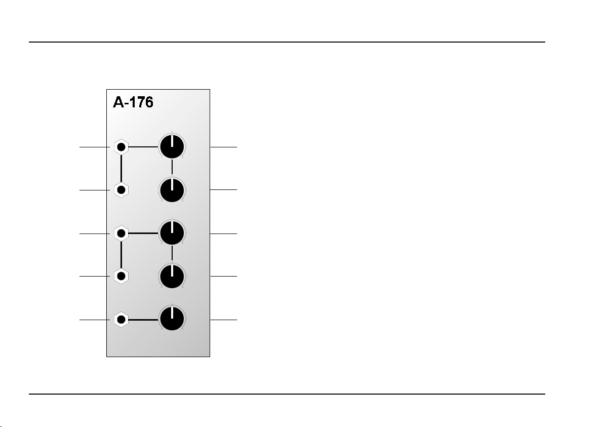
2. Overview
CVS
Contr. Volt. Source
CV 1
CV 1
10
0
Fine
10
0
CV 2
CV 2
10
0
Fine
10
0
CV 3
CV 3
10
0
➀
➁
➂
➃
➄
Controls:
1
2
3 CV 2 : Coarse control for the voltage at
Fine : Fine control for the voltage at linked
4
CV 3 : Control for the voltage at output
5
: Coarse control for the voltage at
CV 1
linked outputs ! and "
: Fine control for the voltage at linked
Fine
outputs ! and
linked outputs § and
outputs § and
"
$
$
%
Outputs:
!, " CV 1 : Parallel outputs for CV source one
: Parallel outputs for CV source two
CV 2
§, $
CV 3 : Output for CV source three
%
2
Page 3

doepfer
System A - 100
Control Voltage Source A-176
3. Controls
1 CV 1 • 3 CV 2
Controls 1 and 3 provide coarse adjustment of the
voltages at outputs ! and ", and § and $ respectively.
The range of controls 1 and 3 is approximately 5 V.
2 Fine • 4 Fine
Controls 2 and 4 provide precision adjustment of
control voltages CV 1 (at outputs ! and ") and CV 2
(at outputs § and $) respectively.
The range of controls 2 and 4 is approximately 0.1 V.
5 CV 3
This knob sets the
The range of this control is approximately
control voltage CV 3
, at output %.
.
5 V
4. Outputs
! CV 1 • " CV 1
These are the internally connected
for the first CV source, whose level is set by controls
and 2.
1
§ CV 2 • $ CV 2
These are the internally connected parallel outputs
for the second CV source, whose level is set by
controls 3 and 4.
% CV 3
This is the output for the third CV source, whose
level is set by control 5.
H The voltage range for each of the sources
is individually adjustable with jumpers on the
circuit board, either to 0 V - 5 V or symmetri-
cal around zero
(-2.5 V to +2.5 V).
parallel outputs
3
Page 4

A-176
Control Voltage Source
System A - 100
doepfer
5. User examples
Expanding other modules’ facilities
Module A-176 is always going to be useful when you
need a manually controlled voltage which is not available on a particular module itself.
For instance, you can give the A-132 low cost VCA
manual control of its gain voltage, by patching in an
A-176, and using the coarse and fine controls of one of
its CV sources to set the gain (see Fig. 1).
A-176
Contr. Volt. Source
CV 1
CV 1
Fine
In Out
}
Gain
A-132
CV 2
CV 1
CV
Improving tuning on the A-110 VCO
In contrast with the A-111 High End VCO, the A-110
standard VCO only has one control (Tune) for tuning.
The range of this control has to be a compromise - it
has a maximum range of only about an octave, but its
fine tuning ability still isn’t very precise.
With the A-176, it’s possible to overcome these limitations, by patching the output from either the first or
second voltage source into the CV2 input on the A-110
(see Fig. 2).
The VCO's frequency is then determined by a combination of the Range and Tune settings on the A-110,
and the sum of the voltages going into the pitch CV
input CV 1 and the external control voltage input CV 2.
Using the voltage source’s coarse controller 1 or 3
you then have far wider manual control of the range of
the A-110 at the selected footage; and with the voltage
source’s fine controller 2 or 4 you can fine tune the
A-110 with great precision.
: Providing gain control for an A-132 VCA.
Fig. 1
4
Page 5

doepfer
System A - 100
Control Voltage Source A-176
SYNC
A-110
CV
CV 2
CV 1
CV 2
VCO
Range
Tune
A-176
Contr. Volt. Source
CV 1
CV 1
Fine
Tune
}
Fig. 2: Coarse and fine tuning an A-110 VCO.
Recalling pre-set CV values
Combined with an A-150 (or A-151) voltage-controlled
switch, the A-176 can be used as a source of preprogrammed voltages.
A control voltage CV
depending on its voltage, sends CV1 or CV2 from the
A-176 to the A-150’s output. This original control
voltage CV
can come from a MIDI controller via an
S
A-190 or A-191 MIDI interface. That can give you, for
example, velocity or aftertouch switching of filter
modulation intensity (see Fig. 3).
is patched into the A-150, and,
S
Control voltage CV
can also come from a
S
sequencer
(for instance the A-160 / A-161 or MAQ 16/3), to
change volume levels each time a pattern repeats.
CV
S
A-150
CV 1
A-176
CV 2
LFO
: Using a voltage-controlled switch to alternate
Fig. 3
CV
I/O 1
I/O 2
O/I
A-132
VCO
VCF
between two pre-programmed modulation levels.
5
Page 6

A-176
Control Voltage Source
6. Patch-Sheet
System A - 100
doepfer
The following diagrams of the module can help
you recall your own Patches. They’re designed so
that a complete 19” rack of modules will fit onto an
A4 sheet of paper.
Photocopy this page, and cut out the pictures of
this and your other modules. You can then stick
them onto another piece of paper, and create a
diagram of your own system.
Make multiple copies of your composite diagram,
and use them for remembering good patches and
set-ups.
P • Draw in patchleads with colored
pens.
• Draw or write control settings in the
little white circles.
CVS
Contr. Volt. Source
CV 1
CV 1
10
0
Fine
10
0
CV 2
CV 2
10
0
Fine
10
0
CV 3
CV 3
10
0
CVS
Contr. Volt. Source
CV 1
CV 1
10
0
10
0
CV 2
CV 2
10
0
10
0
CV 3
CV 3
10
0
Fine
Fine
CVS
Contr. Volt. Source
CV 1
CV 1
10
0
Fine
10
0
CV 2
CV 2
10
0
Fine
10
0
CV 3
CV 3
10
0
6
 Loading...