

Page 1

doepfer
A-174
Joy Stick controlled CV
Y
X
CV
CV
Y
+
Offset
-
X
+
Offset
-
System A - 100
1. Introduction
Module A-174 (Joy Stick) outputs 2 control voltages
generated by a spring-loaded X/Y cross potentiometer
(so-called joy stick). If the spring is removed for one
direction the joy stick is no longer spring-loaded for this
direction (as the spring is destroyed when removed
this cannot be re-established !).
For each output the voltage offset (zero setting) can
be adjusted. Each output is equipped with
positive/negative display of the output voltages.
Module A-174 is an universal two-dimensional control
voltage source to control the parameters of other
A-100 modules by hand, e.g. filter frequency or resonance (VCF), loudness or modulation depth (VCA),
stereo-panning (A-134), quad-panning (2xA-134), phasing (A-125), frequency shift (A-126), morphing (A-135
+ A-144), pitch bend (VCO), modulation speed (A-
147), decay (A-142) or other envelope parameters
(A-141) and many more.
Joy Stick
A-174
s for
2 LED
A high quality joy stick manufactured by ALPS is used
in the A-174.
1
Page 2
A-174
Joy Stick
System A - 100
doepfer
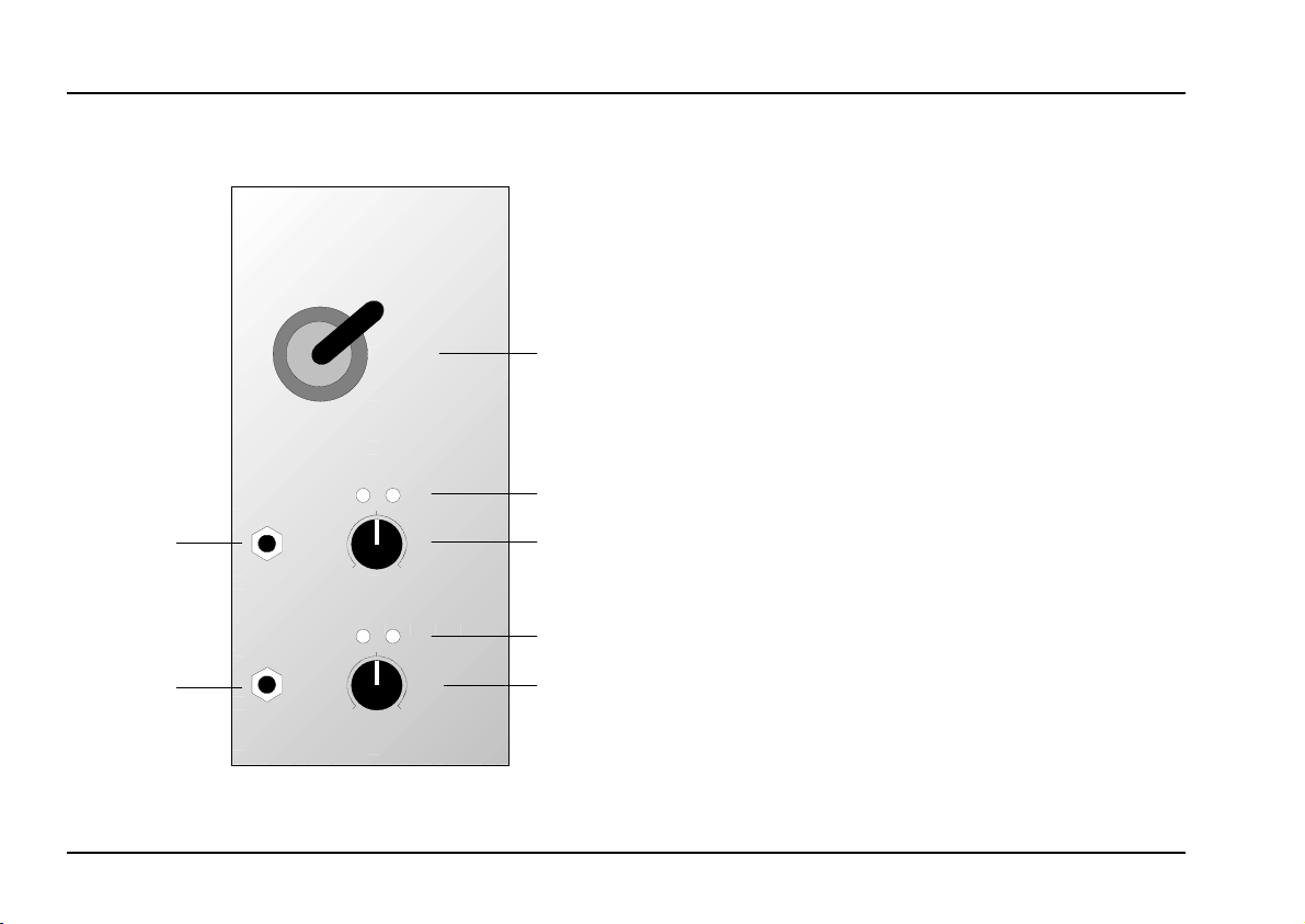
2. Overview
X
Y
X
Joy Stick
+
-
10
0
+
-
10
0
A-174
Joy Stick controlled CV
Y
CV
CV
Offs.
Offs.
➀
➂
➁
➄
➃
Controls:
1 X Y : Joy Stick (cross potentiometer)
2 Offs. : Offset control for Y control voltage
3 LED’s : Display of Y control voltage
4 Offs. : Offset control for X control voltage
5 LED’s : Display of X control voltage
In- / Outputs:
!
"
(X = controlled by horizontal movement
Y = controlled by vertical movement)
: Control voltage output Y
CV Y
X: Control voltage output X
CV
2
Page 3

doepfer
3. Controls
System A - 100
Joy Stick
A-174
1 X Y Joy Stick
With the Joy Stick 1 the
control voltages
at the CV outputs ! resp. " are adjusted. The output
voltage range is about 7 V, i.e. about -3.5 V ... +3.5 V
with symmetrical offset adjustment (i.e. 0V in the neutral position).
The control voltage CV X is controlled by horizontal,
CV Y by vertical movement of the joy stick lever. The
following assignment applies:
X: -3.5
Y: +3.5
X: -3.5
Y: 0
X: -3.5
Y: -3.5
X: 0
Y: +3.5
X: 0
Y: 0
X: 0
Y: -3.5
X: +3.5
Y: +3.5
X: +3.5
Y: 0
X: +3.5
Y: -3.5
The actual voltages appearing at the CV outputs depend also on the settings of the offset controls 2 resp.
.
4
appearing
P The joy stick used in the A-174 module is
spring-loaded, i.e. the lever returns back to
the neutral position as soon as it is released.
If the spring is removed for one direction the
joy stick is no longer spring-loaded for this
direction. But as the spring is destroyed
when removed this cannot be re-established
! The joy stick is available as spare part
(about US$35.00).
2 Offs. Y • 4 Offs. X
With the offset control 2 resp. 5 the zero point (offset)
is adjusted. If 0V CV output is required in the neutral
position the offset control is adjusted until both LEDs
3
resp. 5 of the direction in question are off. For some
applications a positive offset may be useful (e.g. for
A-132 VCA control).
3 LEDs Y • 5 LEDs X
The LEDs 3 resp. 5
appearing at the outputs ! resp. ". For both positive
(+) and negative (-) voltages a separate LED is available.
display the present voltages
3
Page 4

A-174
Joy Stick
System A - 100
doepfer
4. In- / Outputs
! CV Y
This socket outputs the Y control voltage controlled
by vertical movement of the joy stick lever.
" CV X
This socket outputs the X control voltage controlled
by horizontal movement of the joy stick lever.
5. User examples
Module A-174 generates 2 manually adjusted control
voltages that can be used to control any parameter in
the A-100 system that is voltage controlled. Thus there
are manifold applications depending upon the modules
available in the existing A100 system.
Here is a list of some typical examples:
• Filter control
e.g. CV X : frequency, CV Y : resonance
• Mixing of audio or CV signals
e.g. CV X: CV for VCA 1 controlling level 1, CV Y:
CV for VCA 2 controlling level 2, both VCA outputs
are mixed together in an A-138
• Panning / Loudness
CV X : panorama position (CV for A-134),
CV Y : overall loudness (CV for 2 final VCAs)
4
Page 5
doepfer
A-174
JP
Audio In
A-130
System A - 100
A-130
A-130
Joy Stick
A-174
VP
YX
A-175
A-175
A-130
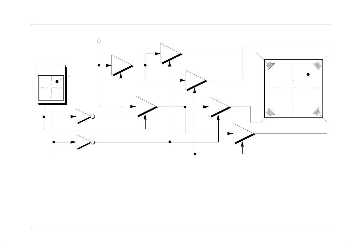
The patch in fig. 1 shows how a A-174 can be used to
move the position of an audio signal in the quadrophonic hearing space. The mechanical position “JP” of the
joy stick lever corresponds to the virtual position “VP”
of the audio signal.
A-130
A-130
Fig. 1: Controlling the virtual position of an audio
signals in the quadrophonic hearing space
(each combination of one A-175 and two A130 can be replaced by a A-134 VC Panning
module).
5
Page 6

A-174
Joy Stick
System A - 100
6. Patch-Sheet
The following diagrams of the module can help you
recall your own Patches. They’re designed so that a
complete 19” rack of modules will fit onto an A4 sheet
of paper.
A-174
Joy Stick cont rolled CV
Y
Joy Stick
doepfer
A-174
Joy Stick cont rolled CV
Y
Joy Stick
Photocopy this page, and cut out the pictures of this
and your other modules. You can then stick them
onto another piece of paper, and create a diagram of
your own system.
Make multiple copies of your composite diagram, and
use them for remembering good patches and set-ups.
P
• Draw in patchleads with colored pens.
• Draw or write control settings in the little
white circles.
6
CV
CV
X
+
-
Y
X
Offs .
10
0
+
-
Offs .
0
10
CV
CV
X
+
-
Y
X
Offs .
10
0
+
-
Offs .
0
10
Remark:
The joy sticks are equipped with a M3 thread. In the
factory a black plastic lever (about 4 cm in length) is
srewed to this thread. You may unscrew this lever and
replace it by any other lever equipped with a M3
thread (e.g. telescope antennas with M3 thread are
available).
 Loading...