

Page 1
doepfer
CV 2
CV 1
CV 2
In
In
Out
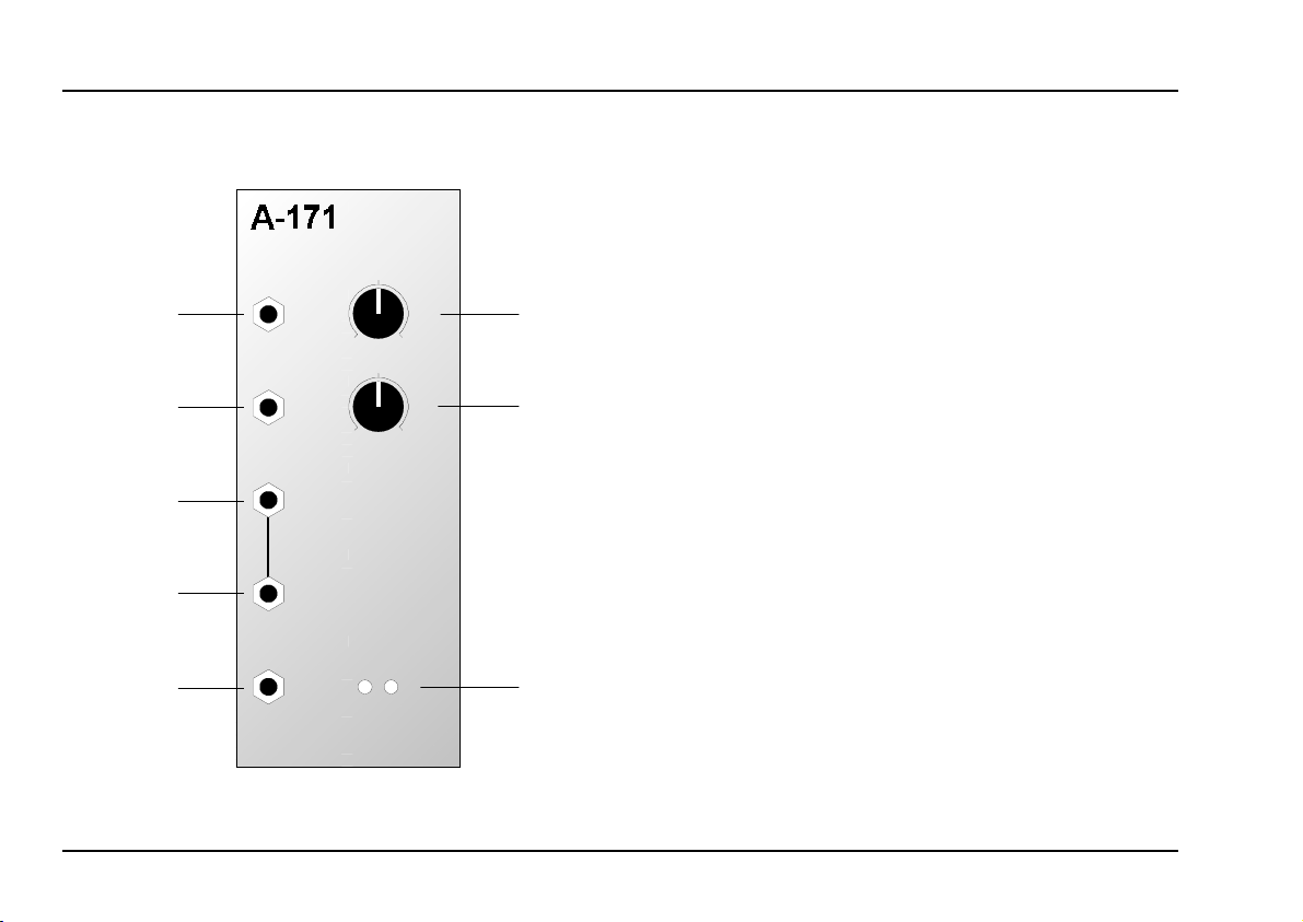
A-171
VC SL
Rate
-
Control
+
System A - 100
1. Introduction
Module A-171 is a voltage controlled slew limiter,
otherwise known as a
grator.
Whenever there is an abrupt transition in the voltage
present at the input, the Slew Limiter works as an
integrator
signal - so that abrupt transitions are sloped. The
speed of the transition is governed by the rate control.
As well as manual setting of this slope, the A-171 also
gives you the possibility of voltage control of the
slope’s gradient by patching in an appropriate voltage to two CV inputs, one of which has an attenuator
for level adjustment.
Two LEDs serve as status indicators to show the
relative amounts of positive and negative signals at the
output.
VC Slew Limiter
portamento controller
, slowing down the transitions in the output
A-171
or
inte-
1
Page 2
A-171
VC Slew Limiter
System A - 100
doepfer
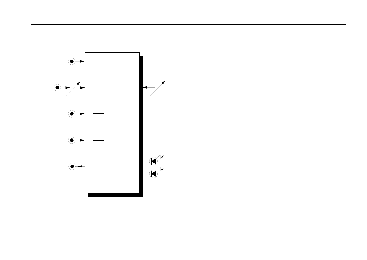
2. Overview
CV 1
CV 2
Sign. In
Out
VCSL
VC SLEW LIMITER
Rate
10
0
CV 2
10
0
-
+
Control
➀
➁
➂
Controls and indicators:
Rate : control governing the transition speed
1
of the modified signal
: attenuator for control voltages at
CV 2
2
LEDs : status indicators for voltages at
3
output %
In / Outputs:
CV 1 : input for voltages to control transition
!
speed
"
§ Sign. In : signal input
$
%
: ditto, but with level controlled by
CV 2
Sign. In
Out
: ditto, interconnected with § (and so a
: output
attenuator
"mini multiple")
2
"
2
Page 3
doepfer
System A - 100
VC Slew Limiter
A-171
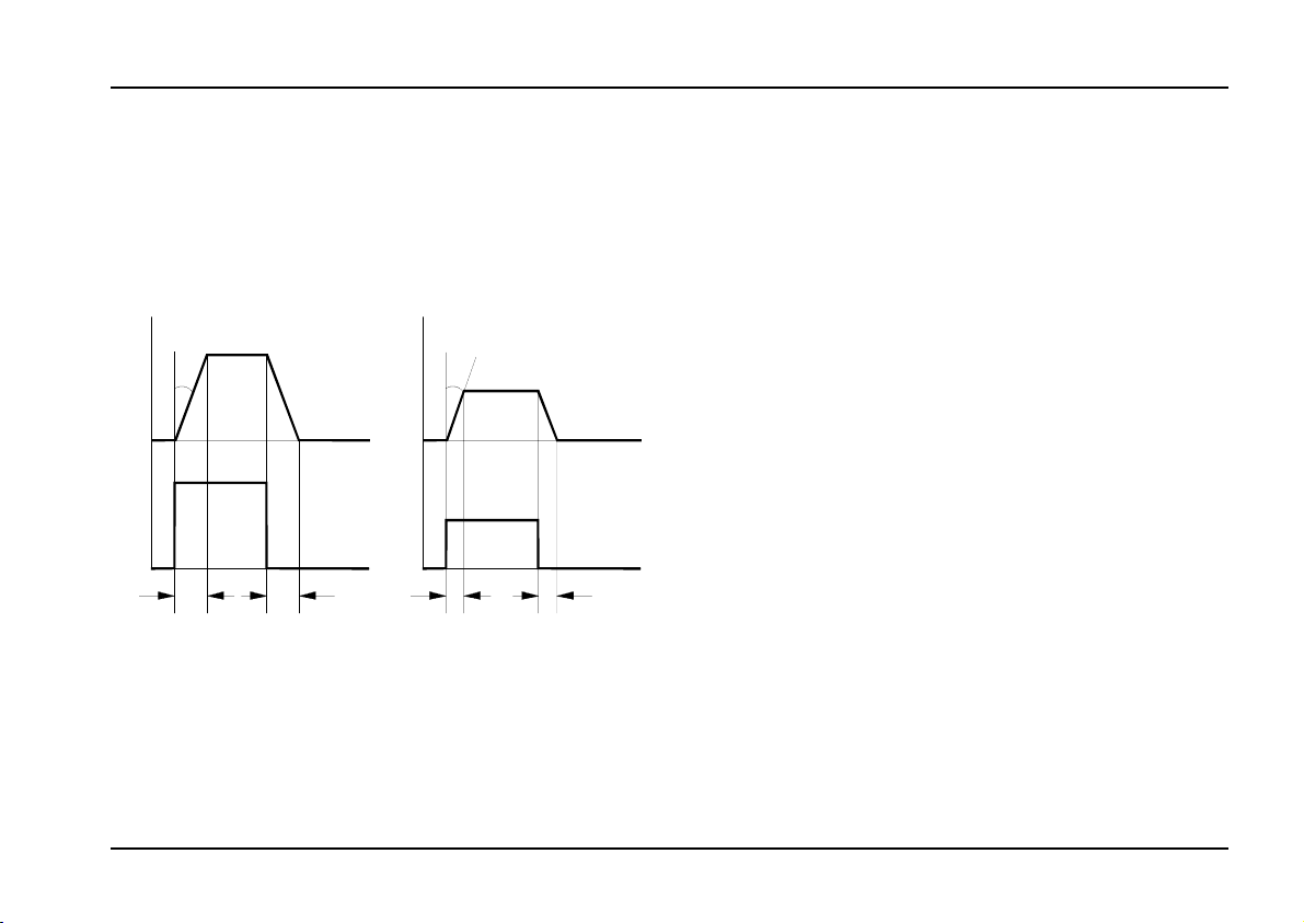
3. Controls and indicators
1 Rate
With this control you adjust the transition speed of the
slope created by the slew limiter (see Fig. 1). The
speed can be adjusted to produce transitions from
about 10 down to nearly 0 seconds.
Out
αααα αααα
In
t
S
t
S
Fig. 1: How the A-171 transforms a signal.
When Rate = 10, the output signal is nearly identical
to the input, i.e. the max. slew speed or min. slew time
is selected. When Rate = 0 one obtains the minimum
slew speed (= maximum slew time, i.e. ~ 10 seconds).
Out
In
t
S
t
S
Pay attention that the control behaviour of the
H
A-171 is reverse that of the "normal" slew limiter A-170. The control of A-171 is controls the
speed (rate), the controls of the A-170 control
the time.
2 CV 2
Use Attenuator 2 to control the amount of CV input
to affect the transient speed.
"
3 LEDs
The LEDs 3 are status indicators of the relative mix
of positive ("+") and negative ("-") signals at the output.
The brighter they are, the higher the voltage.
3
Page 4

A-171
VC Slew Limiter
System A - 100
doepfer
4. In / Outputs
! CV 1 • " CV 2
The transition speed produced by the A-171 depends
on a combination of the setting on the Rate control,
and any voltages patched into the CV inputs ! and ".
The level of the voltage at CV input " can be controlled by attenuator 2.
Sign. In • $ Sign. In
§
These interconnected sockets are the signal input to
the VC Slew Limiter. Whatever signal is patched in to
these inputs will have any sudden voltage jumps
smoothed into more gradual rises and falls, at a rate
depending on the manual control and the CV inputs.
% Out
The modified signal is available at output %.
5. User examples
Voltage controlled slew limiting in a MIDI
system
Unlike the A-170 Slew Limiter, the A-171 can have the
rate of rise and fall voltage controlled.
In particular, there’s the possibility of controlling the
Rate parameter via a MIDI-CV interface (eg. A-190,
A-191) as you
makes use of this feature.
play in real time
Adjustable portamento
The example in Fig. 2 uses the A-171 as a portamento generator
and with this patch can be controlled from a MIDI
keyboard. Simply set the A-191’s CV2 output to your
chosen MIDI controller (eg. Portamento Time). Pay
attention that an increasing control voltage causes a
shorter transition time. To obtain the opposite behaviour a voltage inverter A-175 can be used (A-191 CV
output -> A-175 input, A-175 output -> A-171 control
input).
. The portamento time is adjustable,
. The next example
4
Page 5

doepfer
System A - 100
Slew Limiter as VC AR generator
You can also use the A-171 as a simple AR generator, for instance with the percussive sound in the
example in Fig. 3. The attack/release parameters can
be controlled by MIDI, for instance by the voltage at
the CV2 output on the A-190.
MIDI
MIDI In
A-190
CV 1
VC Slew Limiter
A-171
CV 1/2
A-171
MIDI
MIDI In
A-190
CV 1
CV 2
Gate
VCO VCF
A-171
CV 1/2
ADSR
CV 2
Fig. 2: A-171 as real-time
controlled portamento generator.
VCA
Fig. 3:A-171 as
VC AR Generator.
VCO
gliss. gliss.
5
Page 6

A-171
VC Slew Limiter
System A - 100
doepfer
Producing complex controllable modulations
With a combination of a Clock Divider / Sequencer
(A-160 / A-161) and a series of A-171 VC Slew
Limiters, complex modulation systems are possible
(see Fig. 4).
The Clock Sequencer is patched into a series of Slew
Limiters, each set to produce a different envelope.
These envelopes are patched into an A-138 Mixer (the
version with linear response) .
The level of each of the envelopes is adjusted with the
mixer.
With the help of an A-191 MIDI-CV converter and a
suitable MIDI Controller, you can control the rise and
fall rates of the envelopes in real time.
In the patch in Fig. 4, the clock sequencer is triggered
by the internal MIDI-synced LFO in the A-191 converter. Alternatively, you can use a free-running LFO to
trigger the sequencer.
P
Try expanding this patch by adding another
control voltage ingredient into the inputs at
the A-138 mixer, as well as the envelopes
from the slew limiters - for instance:
• ADSR with a slowish envelope, triggered
from the first of the A-161’s outputs,
• the output from an LFO (with or without
Reset),
• Random output from an A-118,
• Audio signals in connection with the A119 Envelope Follower.
A-171 as DC coupled low pass filter
The A-171 can be used as a simple DC coupled filter
("DC coupled" means, that even very slow sub-audio
frequencies can be filtered). An example is the usage
of the A-171 as external low pass filter for the PLL
module A-196. For details refer to the A-196 manual.
6
Page 7

doepfer
System A - 100
VC Slew Limiter
A-171
A-161
Clock
Sequencer
1
2
3
4
5
6
7
8
MIDI
A-191
MIDI In
S90 /LFO
C 1
C 2
A-160
Clock
Divider
Trig.
In
Fig. 5: Producing complex controllable modulations.
A-171
A-171
A-138 a
In 1
In 2
In 3
In 4
Input 1
Input 2
Input 3
Input 4
MIXER
Output
Out
7
Page 8

A-171
VC Slew Limiter
6. Patch-Sheet
System A - 100
doepfer
The following diagrams of the module can help
you recall your own Patches. They’re designed so
that a complete 19” rack of modules will fit onto an
A4 sheet of paper.
Photocopy this page, and cut out the pictures of
this and your other modules. You can then stick
them onto another piece of paper, and create a
diagram of your own system.
Make multiple copies of your composite diagram,
and use them for remembering good patches and
set-ups.
P • Draw in patchleads with colored
pens.
• Draw or write control settings in the
little white circles.
CV 1
CV 2
Sign. In
Out
VCSL
VC SLEW LIMITER
Rate
10
0
CV 2
10
0
-
+
Control
CV 1
CV 2
Sign. In
Out
VCSL
VC SLEW LIMITER
Rate
10
0
CV 2
10
0
-
+
Control
CV 1
CV 2
Sign. In
Out
VCSL
VC SLEW LIMITER
Rate
10
0
CV 2
10
0
-
+
Control
8
 Loading...