

Page 1
doepfer
A-165
TRIG. MODIF.
In
In
Inv.
Out
+/-
Out
System A - 100
1. Introduction
Module A-165 (Dual Trigger Modifier) contains two
separate trigger modifiers, to use with logical / digital
levels (Gate, Clock, Trigger). Each half of the module
enables signals generated by the A-100 to communicate with other instruments (such as an external sequencer), or is simply used where you want to reverse
a trigger polarity.
Whatever signal is patched into the input is inverted by
the module, and fed out of the Inv. Out (inverted
output
) socket.
Dual Trigger Modifier
A-165
+/-
Out
In
In
Inv.
Out
At the same time, a trigger signal of roughly 50 ms is
generated every time an edge of the trigger pulse is
sensed (negative as well as positive). This trigger
signal is available at the +/- output.
Two LEDs act as indicators showing the level of signal
available at the two outputs.
1
Page 2
A-165
Dual Trigger Modifier
System A - 100
doepfer
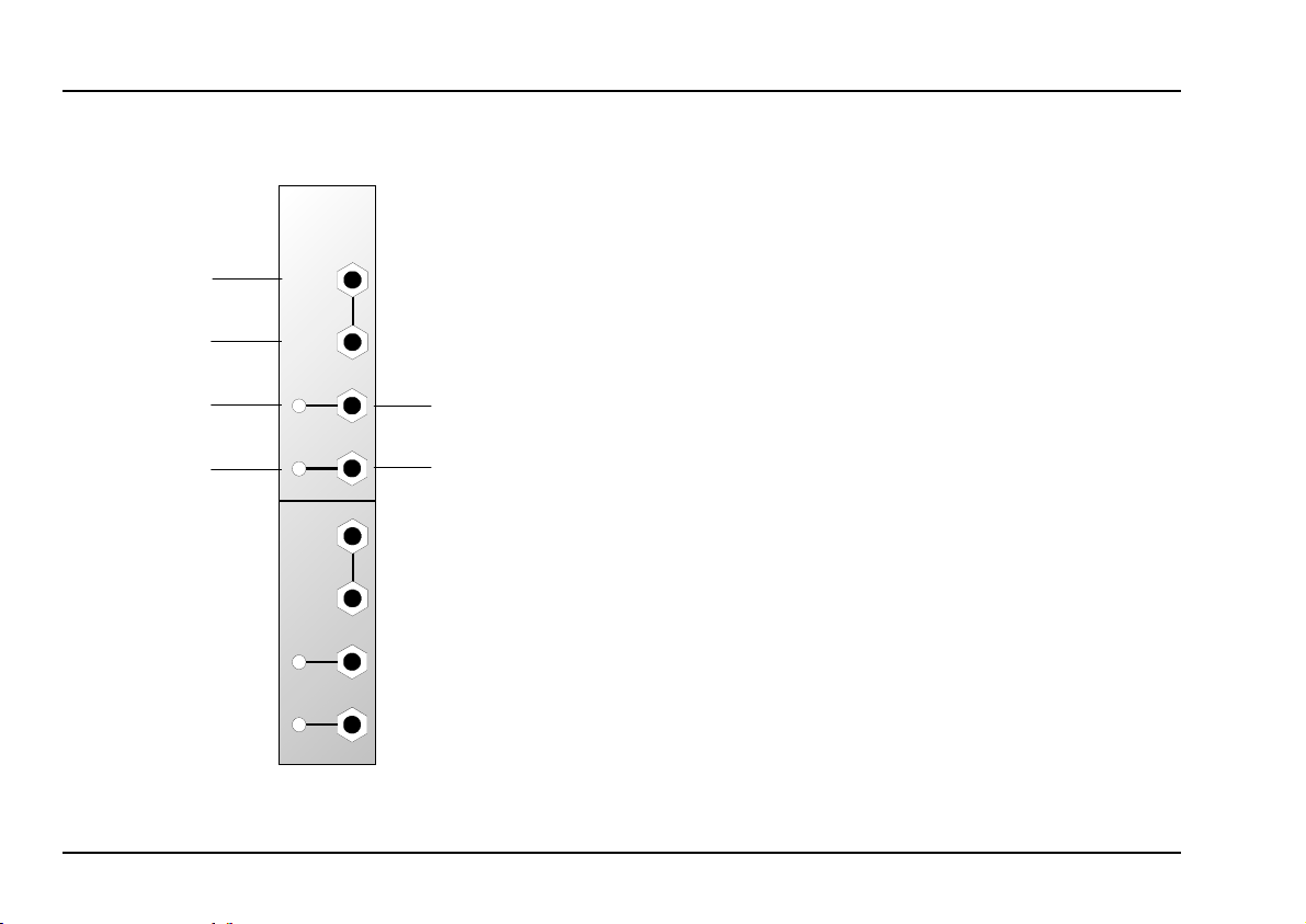
2. Overview
➀
➁
A-165
TRIG. MO DIF.
In
In
Inv.
Out
+/-
Out
In
In
Inv.
Out
+/-
Out
Indicators
LED : Status indicator for the inverted trig-
1
ger signal at output §
: Status indicator for the trigger pulse
LED
2
generated, and available at output
In / Outputs
In : Input for trigger signal
!
" In : ditto, linked to input !
Inv. Out
§
+/- Out : Output for the trigger pulses genera-
$
: Output for the inverted trigger signal
ted by the A-165
$
2
Page 3

doepfer
System A - 100
Dual Trigger Modifier
A-165
3. Indicators
1 LED
This LED is the status indicator for the inverted
trigger signal at output §.
2 LED
This LED is the
pulses the A-165 generates, available at output $.
status indicator for the trigger
4. In / outputs
! In • " In
Sockets ! and " are the interconnected Inputs to the
A-165. This is where the trigger signal to be modified
is patched in.
P
In practice, the original and inverted trigger
signal are often both needed at the same
time, so it’s possible to use these two inputs
as a mini-multiple - using one of them to
send the original trigger to another module.
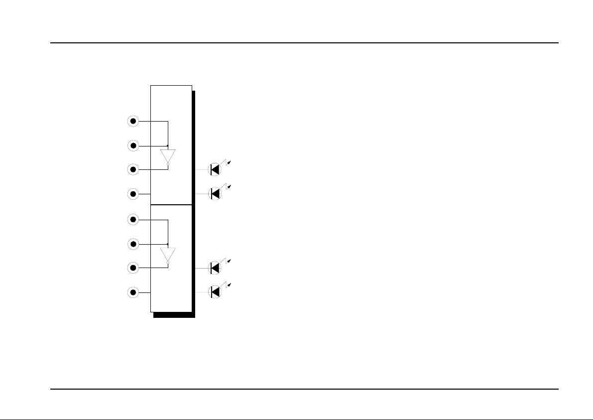
§ Inv. Out
The inverted trigger signal is available at output §
(see Fig. 1).
$ +/- Out
Output $ carries the trigger signals generated by both
the leading and falling edges of the original trigger
signal (pulse length: approx. 50 ms). See Fig. 1.
+/-
Out
Inv.
Out
In
Fig. 1: How the A-165’s outputs relate to the input.
w
3
Page 4

A-165
Dual Trigger Modifier
System A - 100
doepfer
5. User examples
Repeating notes played on keyboard
In the patch in Fig. 2 each note played on the keyboard
produces two sounds: the first when the key is pressed, and the second when it’s released.
To achieve this, output $ (+/-) on the A-165 is used.
The ADSR attack time needs to be very short.
CV
Gate
VCO
A-165
+/- Out
Fig. 2: Double sounds from single notes played.
VCF
ADSR
VCA
Repeating notes with ping-pong echo
A modification of the previous patch is shown in Fig. 3.
In this case, the sound is repeated when the key is
released, but this time from a different output: at the
original key-press, the sound goes to one VCA (
and on release goes to the other VCA (Out
CV
A-131
Gate
VCO
VCF
ADSR
A-131
A-165 ADSR
Inv. Out
Fig. 3: Repeating notes with ping-pong echo effect.
Out
).
R
L
Out
Out
),
L
R
The patch sounds particularly good if the triggering is
provided by a sequencer (like the MAQ 16/3) instead
of a keyboard.
4
Page 5

doepfer
System A - 100
Dual Trigger Modifier
A-165
5
Page 6

A-165
Dual Trigger Modifier
6. Patch-Sheet
System A - 100
doepfer
The following diagrams of the module can help you
recall your own Patches. They’re designed so that a
complete 19” rack of modules will fit onto an A4
sheet of paper.
Photocopy this page, and cut out the pictures of this
and your other modules. You can then stick them
onto another piece of paper, and create a diagram of
your own system.
Make multiple copies of your composite diagram,
and use them for remembering good patches and
set-ups.
P • Draw in patchleads with colored pens.
A-165
TRIG. MODIF.
In
In
Inv.
Out
+/-
Out
In
In
Inv.
Out
+/-
Out
A-165
TRIG. MODIF.
In
In
Inv.
Out
+/-
Out
In
In
Inv.
Out
+/-
Out
A-165
TRIG. MODIF.
In
In
Inv.
Out
+/-
Out
In
In
Inv.
Out
+/-
Out
6
 Loading...