

Page 1

doepfer
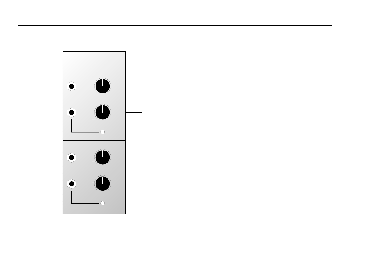
In
Out
Control
In
A-162
TDEL
Del.
Len.
System A - 100
1. Introduction
Module A-162 (Dual Trigger Delay) contains two
separate delay circuits for trigger signals.
This module makes it possible to delay the onset of a
trigger pulse, and also change its length (see Fig. 1 on
page 3).
On each of the trigger delays, two controls can alter
the onset time and duration of triggers, from 0 up to
round about ten seconds. A control LED indicates the
onset and duration of the new trigger.
Dual Trigger Delay A-162
Out
Control
Del.
Len.
1
Page 2
A-162
Dual Trigger Delay
System A - 100
doepfer
2. Overview
A-162
DUAL TRIGGER DELAY
In
Out
In
Out
TDEL
0
0
Control
0
0
Control
10
10
10
10
Del.
Len.
Del.
Len.
➀
➁
➂
Controls and indicators:
For each trigger delay:
Del. : Delay control
1
2 Len. : Trigger length control
: Trigger pulse output indicator
LED
3
In / Outputs:
: Trigger signal input
In
!
Out : Output
"
2
Page 3

doepfer
System A - 100
Dual Trigger Delay A-162
3. Controls and indicators
1 Del.
This control sets the trigger delay time tD (see Fig. 1)
in a range from zero to ten seconds.
2 Len.
This control 2 sets the length tL of the trigger pulse
(see Fig. 1) in a range from zero to ten seconds.
3 LED
LED 3 lights when a trigger pulse is being output.
4. In / Outputs
! In
Socket ! is the A-162’s
patch the trigger pulse in whose rising edge will start
the process.
input.
" Out
The delayed trigger signal is output here.
Out
In
t
D
This is where you
t
L
Fig. 1: How the A-162 delays and lengthens a pulse
3
Page 4

A-162
Dual Trigger Delay
System A - 100
doepfer
5. User examples
Modulation delay
The A-162 is particularly useful for delaying the onset
of modulation, for instance of a VCF, VCO, VCA,
etc., by causing the gate to open later. It can also
create pseudo echo effects.
A-132
VCA 1
LFO
Gate
A-162
CV
ADSR
A-170
Fig. 2: Delayed vibrato
VCO
CV
VCA. By patching in an AR envelope (in this case an
A-170, but an A-140 could also do the job) the
intensity of the vibrato can increase and decrease
gradually.
Stereo "Echo"
The patch in Fig. 3 produces a sort of stereo echo.
When a key is pressed, the sound first comes out of
the Out
the A-162, the ‘echo’ comes out of the right VCA
output, Out
left VCA output, and then, after a delay set by
L
.
R
CV
Gate
VCO
VCF
ADSR
A-162 ADSR
A-131
A-131
Out
Out
R
L
In the example in Fig. 2, the onset of vibrato (subaudio frequency modulation of a VCO) is delayed by
using the A-162 to delay the gate which will open the
4
Fig. 3: Stereo "echo"
Page 5

doepfer
System A - 100
Dual Trigger Delay A-162
5
Page 6

A-162
Dual Trigger Delay
6. Patch-Sheet
System A - 100
doepfer
The following diagrams of the module can help
you recall your own Patches. They’re designed so
that a complete 19” rack of modules will fit onto an
A4 sheet of paper.
Photocopy this page, and cut out the pictures of
this and your other modules. You can then stick
them onto another piece of paper, and create a
diagram of your own system.
Make multiple copies of your composite diagram,
and use them for remembering good patches and
set-ups.
P • Draw in patchleads with colored
pens.
• Draw or write control settings in the
little white circles.
A-162
DUAL TRIGGER DELAY
In
Out
In
Out
TDEL
0
0
Control
0
0
Control
A-162
DUAL TRIGGER DELAY
In
Del.
10
Out
Len.
10
In
Del.
10
Out
Len.
10
TDEL
0
0
0
0
10
10
Control
10
10
Control
A-162
DUAL TRIGGER DELAY
In
Del.
Out
Len.
In
Del.
Out
Len.
TDEL
0
0
0
0
Del.
10
Len.
10
Control
Del.
10
Len.
10
Control
6
 Loading...