

Page 1
doepfer
1. Introduction
System A - 100
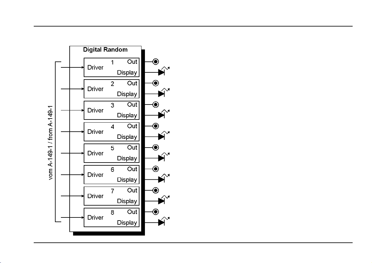
A-149-2 is an extension module for the random voltage
generator A-149-1. It makes available 8 digital random
voltages (i.e. only low/high states like a gate signal).
The outputs are controlled by the "Quantized Random
Voltages" section of the assigned A-149-1 and correspond to the 8 digital outputs of the shift register that is
used to generate the Quantized Random Voltages (for
detailes please refer to the A-149-1 description).
As the alteration of the A-149-2 outputs is clock controlled by the Clock Input of the "Quantized Random Voltages" section of the A-149-1 the A-149-2 can be used to
create random rhythmical sequences.
Module A-149-2 requires module A-149-1 and has to be
assembled next to the A-149-1 into the A-100 frame.
Digital Random
A-149-2
1
Page 2
A-149-2
Digital Random
2. Overview
System A - 100
1 !
doepfer
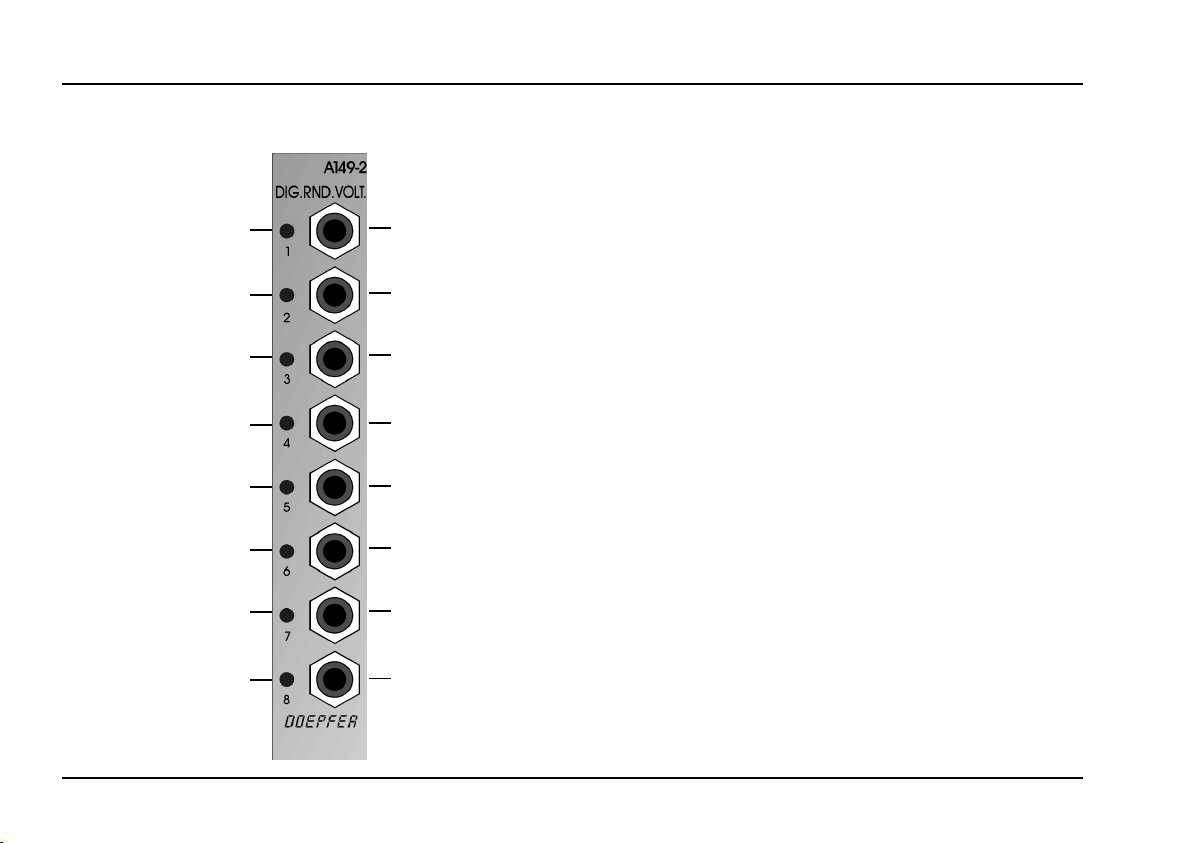
Controls:
1... 8 (LEDs): Display for each output
2 "
3 §
4 $
5 %
6 &
7 /
8 (
2
Outputs:
! ... ( (sockets): Digital outputs
Page 3

doepfer
System A - 100
Digital Random
A-149-2
3. Controls
1...8 (LEDs) / !...( (sockets)
At the sockets !...( the 8 random digital outputs are
available. The output levels are ~ 0V (low state) resp.
+12V (high state).
Each positive clock transition of the "Quantized Random
Voltages" section of the A-149-1 causes a new combination of the A-149-2 output states. The outputs reflect the
digital states of the shift registers used in the A-149-1 to
generate the random voltages. Details about this subject
are available in the A-149-1 manual and on our web site
www.doepfer.com where the method of random voltages
generation with the A-149-1 is described in detail.
As the level changes are triggered by the QRV clock the
A-149-2 outputs have a timing correlation with the clock
signal and can be used e.g. as random gate or trigger
signals with the level changes in sync with the clock.
As the level changes are random even no level change
is possible for a certain output (i.e. the output remains
low or high) as these four level changes are possible:
• low → low
• low → high
• high → low
• high → high.
4. User Examples
not yet ready
3
Page 4

A-149-2
Digital Random
System A - 100
doepfer
Appendix: Connection A-149-1 – A-149-2
Module A-149-2 (Digital Random Voltages) is delivered
with two 10 pin ribbon cables connected to two pin headers on the A-149-2 pc board:
1. One of the ribbon cables is equipped with a 10 pin
female connector on one end and a 16 pin female
connector on the other side. The 10 pin female connector is connected in the factory to the pin header labelled
"JP1" on the A-149-2 pc board. This is the bus
tion cable and the 16 pin female connector has to be
connected to a free pin header of the A-100 bus board.
Pay attention to the right polarity (red wire = bottom).
10 pin female connector
→→→→ JP1 / A-149-2
16 pin female connector
→→→→ bus board
connec-
Please refer to the A-100 user's manual (introduction)
for details concerning correct bus cable connection.
2. The second ribbon cable is equipped with 10 pin
female connectors on both ends. One of the female
connectors is connected in the factory to the pin header
labelled "JP2 TO A-149-1 EXPANSION CONNECTOR"
on the A-149-2 pc board. The second female connector
of this cable is used to establish the connection between
A-149-2 and A-149-1. This female connector is put on
the pin header labelled "JP5 EXPANSION" on the main
board of the module A-149-1. For both modules the
cable has to be the same polarity (i.e. red wire to bottom
for both modules).
10 pin female connector
→→→→ JP5 EXPANSION /
A-149-1
10 pin female connector
→→→→ JP2 TO A-149-1 EX-
PANSION CONNECTOR /
A-149-2
red wire = bottom
4
red wire = bottom
 Loading...