

Page 1
doepfer
A-148
DUAL S&H
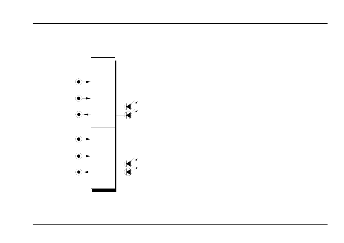
Trig. In
Smp. In
Control
S&H Out
System A - 100
1. Introduction
Module A-148 (Dual S&H) has two identical sample &
hold modules, designed to produce ‘staircase’ voltages.
The signal present at the sample input (voltage range
-8V...+8V) is sampled at a rate set by the signal at the
trigger input, and held at that voltage at the S&H
output.
The exact shape of the staircase depends on the sort
of waveform at the sample input: NOISE or RANDOM
signals produce random patterns; an LFO produces
rising or falling staircase patterns.
Two LEDs for each S&H indicate the voltage (positive
or negative) of the sampled signal.
Dual S&H A-148
Trig. In
Smp. In
Control
S&H Out
From August 2005 an improved version of the module
is manufactured: For each sub-module the operation
mode S&H (sample&hold) or T&H (track&hold) can
be selected by a jumper. In T&H mode the output signal follows the input signal while the trigger input is
"high". As soon as the trigger input turns to "low" the
last voltage is stored. The factory setting is S&H for
the upper device and T&H for the lower device. In addition the complete A-100 voltage range -12...+12V
can be processed (no longer limited to -8...+8V as for
the previous version).
1
Page 2
A-148
Dual S&H
System A - 100
doepfer
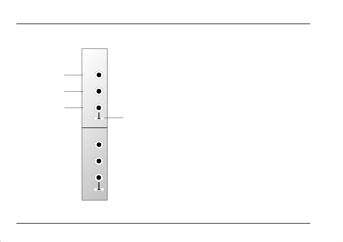
2. Overview
➊
➋
➌
A-148
DUAL S&H
Trig.
In
Smp.
In
S&H
Out
Ctr.
-
Trig.
In
Smp.
In
S&H
Out
Ctr.
-
Indicators:
LEDs: sampled voltage status indicators
1
In / Outputs:
! Trig In : Input for trigger signal
Smp In
"
S&H Out : Output for sampled (and held) voltage
§
+
+
➀
: Input for signal to be sampled
2
Page 3

doepfer
System A - 100
Dual S&H A-148
3. Indicators
1 LEDs
These LEDs give a visual indication of the voltage
level of the sampled and held signal (- LED: negative
voltages, + LED: positive voltages).
4. In / Outputs
! Trig In
The trigger input signal decides the rate at which the
sampling takes place. Triggering takes place at the
leading edge of the waveform (see arrows in Fig. 1),
so the width of the pulse isn’t important.
" Smp. In
Socket " is the sample input, where the signal to be
sampled is patched in. For the old version
(manufactured until August 2005) the signal fed into
this socket has to be in the range -8V...+8V. For
voltages beyond this range the S&H function will not
work any longer. But the module cannot be destroyed
as long as the voltage is in the range -12V...+12V. And
that is the maximum voltage output from any A-100
module. Consequently within the A-100 no damage is
possible.
For the new version of the module manufactured from
August 2005 the complete A-100 voltage range can be
processed (i.e. -12...+12V).
§ S&H Out
The ‘sampled and held’ voltage is available at the S&H
output
Fig. 1
Smp.
(see Fig. 1).
: S&H module signal diagram
S&H
Out
In
Trig.
In
3
Page 4

A-148
Dual S&H
System A - 100
doepfer
5. User examples
Random arpeggios
In the example in Fig. 2, an A-118 is used in conjunction with the A-148 to produce random voltages from
the random output of the A-118. An LFO triggers the
S&H module, so that with every oscillation of the LFO
a new random voltage is output to the VCO’s CV input.
If you patch an A-130 VCA in before the VCO, you can
adjust the Gain and Out amounts to restrict the frequency range of the random voltages to whatever you
want.
A-118
Random
In
Trig. In
LFO
CV 2
VCOS&H
P
You can use the same basic set-up as in Fig.
2, but patch the S & H voltage output to the
CV input of a filter set to high resonance, for
some interesting rhythmic timbral changes
(see page 6).
Glissando
In Fig. 3 an A-148 produces a staircase voltage.
The pitch CV output from a keyboard is patched into
an A-170 Slew Limiter. An A-148 triggered by the
rising edge of an LFO samples the output from the
slew limiter, and produces a staircase voltage which in
turn controls a VCO’s pitch.
Playing two notes, particularly widely spaced ones,
produces interesting glissandi.
H It’s important to adjust the slew limiter’s time
setting and the LFO’s frequency to achieve
the right speed and number of notes in the
glissandi.
Fig. 2: Random arpeggios
4
Page 5

doepfer
System A - 100
Dual S&H A-148
CV
A-170 S&H VCO
LFO
Abb. 3: Glissando
P If you like you can patch the gate signal to
the reset input of the LFO, so that its waveform starts at the beginning for each note.
Instead of an LFO, you can also use the
MIDI-Clock from a MIDI-CV interface. That
will produce glissandi synced to MIDI.
Random filter settings per note
With the patch in Fig. 4, every time a keyboard gate
voltage is received, a new random filter CV is sent
out. For best results, adjust the resonance to a high
setting.
CV
Gate
VCO
VCF
S&HA-118
Random
: keyboard gate triggering random filter settings
Fig. 4
5
Page 6

A-148
Dual S&H
System A - 100
6. Function of the jumpers
(only for the new version manufactured from 2005)
By means of the jumpers JP2 and JP3 the operation
mode can be chosen (S&H or T&H).
The factory setting is S&H for the upper device and
T&H for the lower device.
doepfer
6
 Loading...