

Page 1
doepfer
CV
Reset
CV
A-147
VCLFO
Frequ.
System A - 100
1. Introduction
Module A-147 (VCLFO) is a voltage controlled low
frequency oscillator,
trol voltages over a 0.01Hz to 50Hz frequency range.
The VCLFO can be patched as a modulation source
for a wide range of modules (for instance, modulation
of VCO pulse-width or frequency, VCF cut-off frequency, VCA amplitude modulation) and as a provider
of repetitive or clock voltages (for instance to drive the
A-161 clock sequencer).
Four waveforms are available: triangle, sine, square,
and falling sawtooth waves.
The VCLFO's frequency can be controlled by hand,
but also by voltage control.
You can sync the VCLFO to another waveform by
connecting the other waveform (eg another LFO) to
the VCLFO’s reset input.
VCLFO A-147
which can produce cyclical con-
1
Page 2
A-147
VCLFO
System A - 100
doepfer
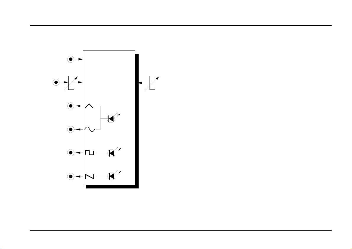
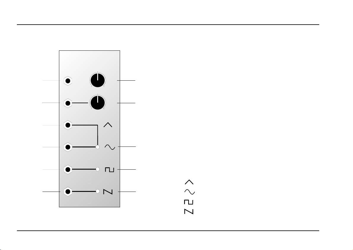
2. Overview
➊
➋
➌
➍
➎
➏
A-147
Voltage Controlled LFO
Reset
CV
0
0
VCLFO
Frequ.
10
CV
10
➀
➁
➂
➃
➄
Controls and indicators:
Frequ. : Manual frequency control
1
2 CV : Attenuator for the voltage at input "
: Frequency indicator for the triangle
LED
3
and sine waves at outputs § and/or
$
: Frequency indicator for the square
LED
4
5
wave at output
: Frequency indicator for the sawtooth
LED
wave at output
%
&
In- / Outputs:
!
CV : Control voltage input
"
§ : Triangle wave output socket
$ : Sine wave output socket
% : Square wave output socket
& : Sawtooth wave output socket
: Reset input for syncing the VCLFO
Reset
2
Page 3
doepfer
System A - 100
VCLFO A-147
3. Controls and indicators
1 Frequ.
This control sets the frequency of the VCLFO in a
range from 0.01 Hz (one cycle every 100 seconds) to
50 Hz (50 cycles a second).
H The actual LFO frequency is determined by a
combination of manual control and any voltage patched into CV input " .
2 CV
Use Attenuator 2 to set the level of the voltage at CV
input " affecting the VCLFO frequency.
3 LED ... 5 LED
LEDs 3 to 5 indicate the frequency and voltage state
of the LFO signals at their respective outputs.
H If the LFO frequency is higher than about 15
to 20 Hz, our persistence of vision means
that the LEDs look permanently on.
4. In- / Outputs
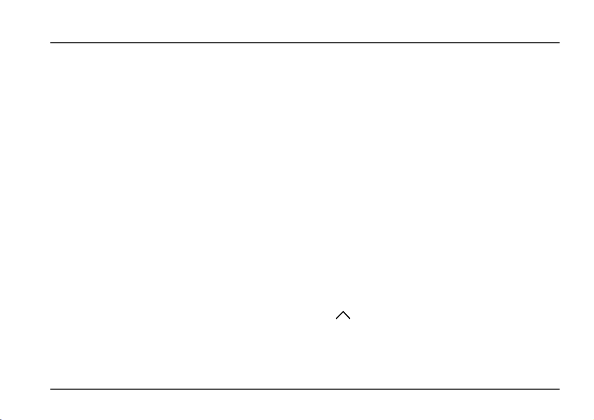
! Reset
A gate pulse entering the
les the VCLFO to be synchronised with another
oscillator.
This means that the waveforms instantly go to their
zero-point, and start from there (see Fig. 1). In the
case of the triangle and sine waves, that’s 0 V; with
the square wave it’s about +5 V and the sawtooth it’s
at half its maximum (about +3.5 V).
reset input socket
" CV
Socket " is the
quency. The voltage at this input is added to whatever
voltage is set on the manual control 1. The level of CV
input " can be adjusted with the Attenuator 2.
voltage control input
§
This socket outputs a triangle wave, whose frequency
is indicated by LED 3 (amplitude roughly ± 5 V).
! enab-
for LFO fre-
3
Page 4

A-147
VCLFO
System A - 100
doepfer
~ +5 V
➌
~ -5 V
~ +5 V
➍
~ -5 V
~ +5 V
➎
~ -5 V
~ +7 V
➏
0 V
➊
Gate
Reset
Reset
Fig. 1: How sync affects the waveforms
$
This socket outputs a sine wave (amplitude range
roughly ± 5 V), whose frequency / voltage state is
indicated by LED 3 .
%
This socket outputs a
± 5 V), whose frequency / voltage state is indicated by
LED 4.
square wave
(amplitude roughly
&
This socket outputs a
(amplitude roughly +7 V) whose frequency / voltage
state is indicated by LED 5.
falling sawtooth wave
H In contrast to the A-145 standard LFO, the
sawtooth is the identical frequency to the
other waveforms (while the A-145 sawtooth
is double the others’ frequency).
4
Page 5

doepfer
System A - 100
VCLFO A-147
5. User examples
An LFO can be used for all sorts of different modulations:
• VCLFO - VCA
Modulation of the VCA gain produces
• VCLFO - VCF
Modulation of the cut off frequency produces cyclical changes in tone colour (wah-wah).
• VCLFO - VCO (PWM)
Pulse width modulation causes cyclical changes in
tone colour.
• VCLFO - VCO (FM)
Pitch modulation produces Vibrato.
All the above refers to modulation in the sub-audio
. With modulation at audio frequencies (the low
range
end of which the VCLFO can just get to), further
changes occur in the sound spectrum. Look at the
examples and suggestions in the manuals of the
respective modules.
tremolo.
Simulating string vibrato
The patch in Fig. 2 shows a string vibrato simula-
, copying the common guitar or violin playing
tion
technique, in which the finger applying the vibrato
moves parallel to the fingerboard, in an oscillation of
varying speed, to produce a pleasing and natural
frequency modulation.
In this patch, the VCO is modulated by the VCLFO
(with the VCO’s CV input attenuator set to a low level).
While the key is held down on the keyboard, the
VCLFO's frequency increases thanks to the control
voltage from ADSR 1; at the same time, the volume
decreases, thanks to the control voltage patched from
ADSR 2 to the VCA.
Instead of ADSR 1, whose control voltage is raising
the frequency of the VCLFO, and thus the speed of the
vibrato, it’s possible to use a MIDI interface (for instance an A-190 or A-191) and use aftertouch to
provide the control voltage to the VCLFO.
5
Page 6

A-147
VCLFO
System A - 100
doepfer
CV
Gate
ADSR 1
VCO
A-147
Reset
CV
ADSR 2
Fig. 2: Simulation of string vibrato
Integrating the VCLFO into a MIDI system
Unlike the A-145 and A-146 LFOs, the A-147’s frequency can be voltage controlled.
This above all gives you the chance to use a MIDI-CV
interface (such as the A-190 or A-191) and use your
chosen controller to
MIDI.
adjust the VCLFO frequency via
VCA 2
That makes the LFO frequency in effect programmable, and also naturally means that you can control it
while playing in real time.
6
Page 7

doepfer
6. Patch-Sheet
System A - 100
VCLFO A-147
The following diagrams of the module can help
you recall your own Patches. They’re designed so
that a complete 19” rack of modules will fit onto an
A4 sheet of paper.
Photocopy this page, and cut out the pictures of
this and your other modules. You can then stick
them onto another piece of paper, and create a
diagram of your own system.
Make multiple copies of your composite diagram,
and use them for remembering good patches and
set-ups.
P • Draw in patchleads with colored
pens.
• Draw or write control settings in the
little white circles.
A-147
Voltage Controlled LFO
Reset
CV
VCLFO
0
0
Frequ.
10
CV
10
A-147
Voltage Controlled LFO
Reset
CV
VCLFO
0
0
Frequ.
10
CV
10
A-147
Voltage Controlled LFO
Reset
CV
VCLFO
0
0
Frequ.
10
CV
10
7
Page 8

A-147
VCLFO
System A - 100
doepfer
8
 Loading...