

Page 1
doepfer
LFO 2
Frequ.
System A - 100
1. Introduction
Module A-146 (LFO 2) is a Low Frequency Oscilla-
, which produces periodic control voltages over a
tor
wide range of frequencies.
The LFO can be used as a modulation source for a
series of modules (for instance pulse width and/or
frequency modulation of a VCO, modulation of a VCF
cut-off frequency, amplitude modulation with a VCA).
LFO 2 A-146
Frequ.
Range
Wave
Form
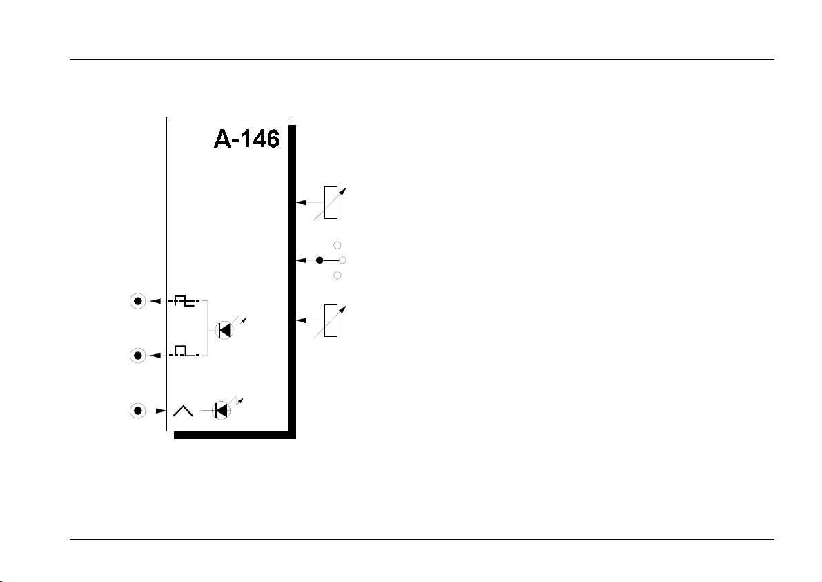
Three outputs are available, with different waveforms:
sawtooth / triangle; square wave, and positivevoltage square wave.
The waveform is continuously adjustable from rising
sawtooth, through triangle to falling sawtooth. The
same control affects the
wave.
A three-way switch can select one of three frequency
ranges, spanning from one cycle every few minutes, at
the lowest, up to audio frequency at the highest.
pulse width
of the square
1
Page 2
A-146
LFO 2
System A - 100
doepfer
2. Overview
➊
➋
➌
LFO 2
Variable Waveform LFO
Frequ.
10
0
Frequ.
M
Range
Wave
Form
L
H
➀
➁
➂
➃
➄
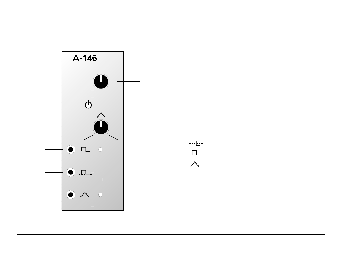
Controls and indicators:
Frequ. : frequency control
1
Frequ. Range : switch for selecting frequency range
2
3 Waveform : control for adjusting the waveform or
pulse width
LED : square wave frequency indicator
4
5 LED : sawtooth / triangle wave frequency
indicator
In / Outputs:
!
"
§
: output for normal square wave
: output for positive square wave
: output for sawtooth / triangle wave
2
Page 3
doepfer
System A - 100
LFO 2 A-146
3. Controls and indicators
1 Frequ.
Use this control to set the LFO’s frequency, within the
range set by 4.
2 Frequ. Range
Use frequency range switch 4 to select a suitable
range from the three available :
(low): up to several minutes per cycle
• L
• M (medium): normal LFO range
• H (high): audio range
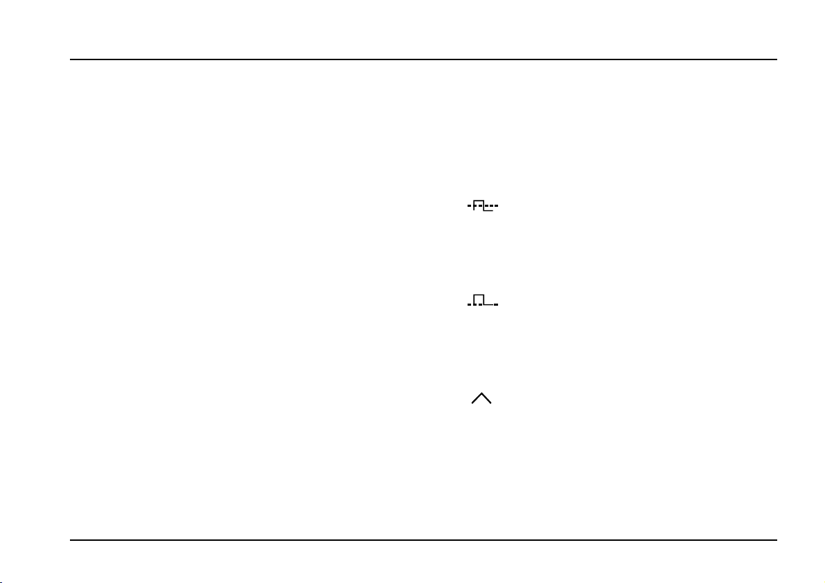
3 Waveform
The waveform of the signal at output § can be continuously varied with this control, from rising sawtooth
(fully left) through triangle (centre position) to falling
sawtooth
pulse width of the rectangle wave at outputs ! and ".
4 LED • 5 LED
LEDs 4 and 5 indicate the frequency rate of the
waveforms at outputs ! to §.
(fully right). The same control alters the
H
If the LFO frequency goes above about 15 to
20 Hz, our persistence of vision means that
the LEDs look permanently on.
4. In / Outputs
!
This socket is the output for the normal (positive /
negative amplitude - ± 2.5 V)
frequency is displayed by LED 4.
square wave
"
This socket is the output for the positive square wave
(amplitude + 5 V), whose frequency is displayed by
LED 4.
§
This output, depending on the setting of control 3,
sends out a rising sawtooth, triangle or falling sawtooth
waveform (amplitude ± 2.5 V) whose frequency is
indicated by LED 5.
, whose
3
Page 4

A-146
LFO 2
System A - 100
doepfer
5. User examples
The LFO can be used for all sorts of modulation:
LFO - VCA
•
Modulation of the amplifier produces periodic changes in
loudness (Tremolo)
• LFO - VCF
Modulation of the cut-off frequency produces periodic changes in timbre (Wah-Wah)
• LFO - VCO (PWM)
Modulation of the pulse width produces periodic
changes in timbre (Pulse Width Modulation)
LFO - VCO (FM)
•
Modulation of the VCO frequency produces periodic changes in
The above effects occur with LFO frequencies in the
sub-audio range
range, timbral changes always occur. Examples and
further notes can be found in the manuals for the
respective modules.
pitch (Vibrato)
. Once the LFO gets into the audio
LFO as timing generator
Besides modulation, the LFO can also be used as a
timing generator, providing triggers, for instance, to
control the A-160 clock sequencer (see user examples
for the A-160 and A-161).
.
A-146 special features and their uses
Compared with the A-145 "standard LFO", the A-146
has the following particular features and uses:
• Variable waveform
The adjustable nature of the sawtooth / triangle
waveform gives you great flexibility in controlling
slow filter sweeps
rising sawtooth on the A-145 ends abruptly, on the
A-146 you can produce whatever slope on the
falling edge you want, by setting the control 3 at
various positions around nine o’clock.
The adjustable envelope also gives flexible control
of Amplitude Modulation (see A-130 user examples) and Frequency Modulation (see A-110, A111 user examples) in the audio range, to produce
new timbres. Whereas the overtone-rich sawtooth
waveform produces lots of sidebands (see the
A-110 manual), moving the control towards the
triangle wave setting (12 o’clock) reduces the sidebands, because of the triangle wave’s comparative
lack of overtones.
or
tremolo
. Whereas the
4
Page 5

doepfer
System A - 100
LFO 2 A-146
• Variable pulse width
In using the square wave for AM or FM in the audio
range, it’s possible to control the
timbre
by adjusting the pulse width, because the amount of overtones (and sidebands) present is directly related to
the width of the pulse.
The A-146’s pulse width control also comes in
useful when using the LFO as a trigger or gate
generator for repeated sequences. The patch in
Fig. 3 is an example: the envelope (set to a duration t
which is shorter than the LFO’s half-cycle),
G,
gives the rhythm a more percussive feel. Whereas
with the A-145, an extra A-162 trigger delay module
would have to be used to adjust the gate duration
(Delay = 0, Length =...) to t
, that’s not the case
G
with the A-146: you simply have to adjust the pulse
width.
• Positive square wave output
This output has the useful function of being able,
unlike a normal positive/negative square wave, to
create pitched repeats which stay in tune.
A-145 A-162 ADSR
t
G
t
G
A-146 ADSR
t
G
t
G
Fig. 3: Producing gate pulses of variable duration
In Fig. 4 on page 6, the pitch of a VCO is controlled by
a CV from a keyboard, but also from the square wave
output of the A-146, via input CV2. The voltage at CV2
is set with the attenuator to exactly 1 volt.
5
Page 6

A-146
LFO 2
System A - 100
doepfer
With the
dulating the pitch, the result is notes that are annoyingly out of tune with the keyboard (see Fig. 4, top right
of diagram).
If instead you use the positive square wave, the
octave jumps are completely in tune with the keyboard (see Fig. 4, bottom right of diagram).
You can use this characteristic in your music, for
instance to produce a mandolin effect. The interval
of the strummed notes is set with the VCO’s CV2
attenuator, and the speed of repeat is set by the
frequency control on the A-146.
normal positive/negative square wave
mo-
CV
A-146
: Producing pitched repeats that are completely
Fig. 4
in tune with the keyboard.
CV1
VCO
CV2
6
Page 7

doepfer
System A - 100
LFO 2 A-146
7
Page 8

A-146
LFO 2
6. Patch-Sheet
System A - 100
doepfer
The following diagrams of the module can help
you recall your own Patches. They’re designed so
that a complete 19” rack of modules will fit onto an
A4 sheet of paper.
Photocopy this page, and cut out the pictures of
this and your other modules. You can then stick
them onto another piece of paper, and create a
diagram of your own system.
Make multiple copies of your composite diagram,
and use them for remembering good patches and
set-ups.
P • Draw in patchleads with colored
pens.
• Draw or write control settings in the
little white circles.
Variable Waveform LFO
LFO 2
Frequ.
10
0
Frequ.
M
Wave
Form
L
H
Range
Variable Waveform LFO
LFO 2
Frequ.
10
0
Frequ.
M
Wave
Form
L
H
Range
Variable Waveform LFO
LFO 2
Frequ.
10
0
Frequ.
M
Wave
Form
L
H
Range
8
 Loading...