

Page 1
doepfer
System A - 100
1. Introduction
Morphing Controller
A-144
CV
CV
Out 1
Out 2
Out 3
Out 4
A-144
MC
Man. Morph
Module A-144 is an extension module for the Voltage
Controlled Mixer A-135
Controller that derives from a linear increasing control voltage at the input (0...+5V) four displaced
triangle voltages (0 bis +5 V). These voltages are
used as control voltages for the Voltage Controlled
Mixer to obtain a fading over (“morphing”) the four
A-135 audio inputs with only one control voltage fed
into the A-144 CV input.
Morphing
nual morphing control and modulated with an external control voltage (e.g. from LFO, ADSR, Random,
MIDI-to-CV, Theremin, Light-to-CV, analog sequencer) with attenuator.
Applications
signals in combination with A-135, e.g. morphing between the 4 waveform outputs of an VCO (sawtooth/
rectangle/ triangle/ sine) or the
multimode filter A-121 (lowpass/ bandpass/ highpass/ notch) or the 4 filter outputs of the A-105
(6/12/18/24dB) to obtain a
led slope.
can be
controlled manually
: voltage controlled morphing of 4 audio
. It is a so-called
4 filter outputs of the
filter with voltage control-
Morphing
with the ma-
1
Page 2
A-144
Morphing Controller
System A - 100
doepfer
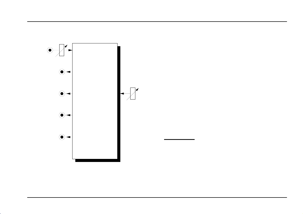
2. Overview
➊
➋
➌
➍
➎
A-144
MC
Morph Controller
CV In
Out 1
Out 2
Out 3
Out 4
0
0
Man. Morph.
Morph CV
Out 3
Out 4
CV
10
10
Out 1
Out 2
➀
➁
Controls:
CV : Attenuator for the control voltage at
1
input !
2 Man. Morph : Manual morphing control
In- / Outputs:
!
Out 1 : Control voltage output 1 (0...+5 V)
"
§ Out 2 : Control voltage output 2 (0...+5 V)
Out 3 : Control voltage output 3 (0...+5 V)
$
% Out 4 : Control voltage output 4 (0...+5 V)
: Control voltage input
CV In
2
Page 3

doepfer
V
System A - 100
Morphing Controller
A-144
3. Controls
1 CV
Use attenuator 1 to adjust the level of the control
voltage at CV input ! affecting the morphing effect.
2 Man. Morph.
Control 2 adjusts the manual morphing.
The module generates an internal control voltage that
is the sum of the voltage generated by the manual
control 2 and the external control ! attenuated with
the attenator 1. This internal control voltage is fed to
the 4 internal control voltage modifiers that generate
the 4 morphing control voltages appearing at the outputs " to $.
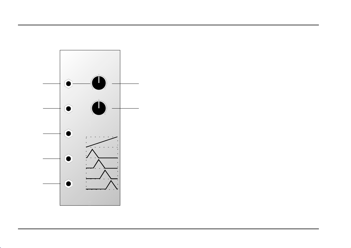
Fig. 1 shows the connection between internal control
voltage and the 4 output control voltages. The internal
voltage is equivalent to the position of control 2 if no
external CV is used, or is equivalent to the external
control voltage ! if manual control 2 is set to 0 and
attenator 1 is turned fully clockwise.
E.g. the control voltage “a” has the following effect:
Out 1 = max. (i.e. +5V) • Out 2 = 0 • Out 3 = 0 • Out
4 = 0.
In case “b” the following output voltages appear:
Out 1 = 0 • Out 2 = 0 • Out 3 = 50 % (i.e. +2.5V) • Out
4 = 50 % (i.e. +2.5V).
CV Out 1
CV Out 2
CV Out 3
CV Out 4
CV In
b
a
+5
0 V
Fig. 1: Connection between internal control voltage
(= sum of manual CV and external, attenuated CV) and the resulting output control voltages (range of input and output voltages is
0...+5V)
3
Page 4

A-144
Morphing Controller
System A - 100
4. In- / Outputs
! CV In
The external control voltage is fed into the CV input
.
!
" Out 1 • ... • % Out 4
The 4 output control voltages are available at the CV
outputs " to % .
CV
Audi o
Out
doepfer
ext.
CV 1
ext.
CV 2
ext.
CV 3
ext.
CV 4
A-135
VC-Mixer
Audio In
Audio Out
1
2
3
4
A-144
MC
CV Out
1
ext.
CV
2
3
4
5. User examples
Morphing (standard application)
The patch in fig. 2 shows the typical application of the
A-144: the fading over (“morphing”) of 4 audio signals
in combination with the voltage controlled mixer module A-135.
An increasing control voltage (typical range 0 -> +5V)
at the CV input of module A-144 results in continuous
“morphing” from audio signal 1 via 2 and 3 to 4.
4
CV Out 1
CV Out 2
CV Out 3
CV Out 4
CV In
: Morphing of four audio signals
Fig 2
Page 5

doepfer
System A - 100
Morphing Controller
A-144
Different control voltage sources lead to interesting
morphing effects:
Automatic morphing
(A-145, A-146), VCLFO (A-147), ADSR (A-140),
VCADSR (A-141) or analog sequencer (A-155).
For manual morphing e.g. these modules can be
used: Theremin (A-178), Light controlled CV (A-179),
Foot controller (A-177), Joy Stick (A-174), MIDI-to-CV
interface (A-190, A-191, e.g. in combination with modulation wheel or after touch).
ca be realized e.g. with LFO
Quadrophonic spatial positioning
In the patch in fig. 3 the A-144 outputs control four
VCAs. The audio inputs of the VCAs may be fed with
the same of even different audio signals. Each VCA is
followed by a separate power amplifier/loudspeaker.
The CV input voltage of the A-144 defines the spatial
position of the audio signal in the quadrophonic spcae.
Additional modules like CV-Phasers (A-125) or CV
frequency shifters (A-126) may be used to intensify the
spatial impression.
Audio InCV In
A-144
Out 1
Out 2
Out 3
Out 4
Fig. 3: Positioning of audio signals in the quadro-
VCA 1
VCA 2
Quad Space
VCA 3
VCA 4
phonic hearing space
A sawtooth control voltage is used to obtain a continuous spatial rotation of the audio signal.
5
Page 6

A-144
Morphing Controller
6. Patch-Sheet
System A - 100
doepfer
The following diagrams of the module can help you
recall your own Patches. They’re designed so that a
complete 19” rack of modules will fit onto an A4 sheet
of paper.
Photocopy this page, and cut out the pictures of this
and your other modules. You can then stick them onto
another piece of paper, and create a diagram of your
own system.
Make multiple copies of your composite diagram, and
use them for remembering good patches and set-ups.
P
• Draw in patchleads with colored pens.
• Draw or write control settings in the little
white circles.
A-144
MC
Morph Controller
CV In
Out 1
Out 2
Out 3
Out 4
0
0
Man. M orph.
Morph CV
Out 3
Out 4
CV
10
10
Out 1
Out 2
A-144
MC
Morph Controller
CV In
Out 1
Out 2
Out 3
Out 4
0
0
Man. M orph.
Morph CV
Out 3
Out 4
CV
10
10
Out 1
Out 2
A-144
MC
Morph Controller
CV In
Out 1
Out 2
Out 3
Out 4
0
0
Man. M orph.
Morph CV
Out 3
Out 4
CV
10
10
Out 1
Out 2
6
 Loading...