

Page 1
doepfer
CV
A-142
Volt. Contr. Decay/Gate
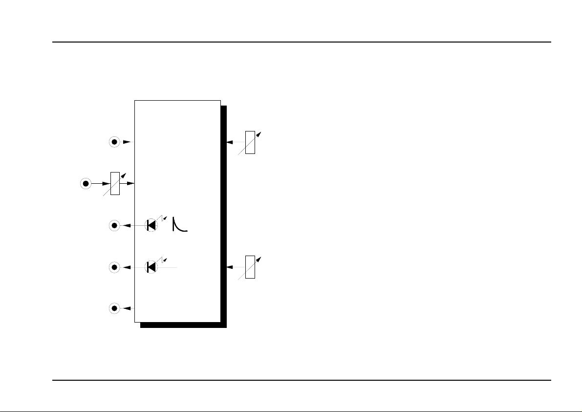
Trig. In
CV
Decay
System A - 100
1. Introduction
Module A-142 (VCD) is a dedicated envelope gene-
with just one parameter,
rator
time is either controlled manually or by voltage control.
Whenever a trigger arrives at the VCD's trigger input,
an envelope is generated. This can then be used to
control VCO, VCF and VCA modules, or any other
module, come to that.
In addition to this, the module produces a gate signal
of adjustable length, which can be output in inverted as
well as normal polarity.
Voltage Contr. Decay / Gate
decay time.
A-142
This decay
Env. Out
Gate Out
Inverse
Gate Out
Threshold
Two
LEDs
signals.
act as indicators of the envelope and gate
1
Page 2
A-142
Voltage Contr. Decay / Gate
System A - 100
doepfer
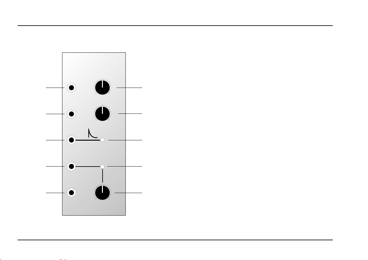
2. Overview
A-142
Volt. Contr. Decay / Gate
Trig. In
CV
Env. Out
Gate Out
Inverse
Gate Out
VCD
0
0
Gate
0
Threshold
Decay
10
CV
10
10
➀
➁
➂
➃
➄
Indicators and controls:
Decay : Manual control for altering the decay
1
time.
: Attenuator for control voltages at CV
CV
2
input
"
3 LED : Indicator for the envelope at output §
LED : Indicator for the gate signal at output
4
$
Threshold
5
: Control to set the trigger threshold,
and thus the length of gate signal
output.
In- / Outputs:
! Trig. In : Input for the trigger signal
: Control voltage input
CV
"
Env. Out : Envelope output
§
$ Gate Out : Output for the gate signal generated
Inv. Gate Out: ditto, except inverted
%
2
Page 3
doepfer
System A - 100
Voltage Contr. Decay / Gate
A-142
3. Controls and indicators
Decay
1
This is used for manual control of the decay time tD of
the envelope generated. After an extremely short attack phase, the envelope runs from maximum to zero
in the time that has been set by this control (see fig. 1).
2 CV
Attenuator 2 is used to set the level of the control
voltage
present at CV input
the length of the decay.
3 LED
LED 3 shows the
sent to output §.
voltage level
4 LED
LED 4 is the indicator for the gate signal at output $.
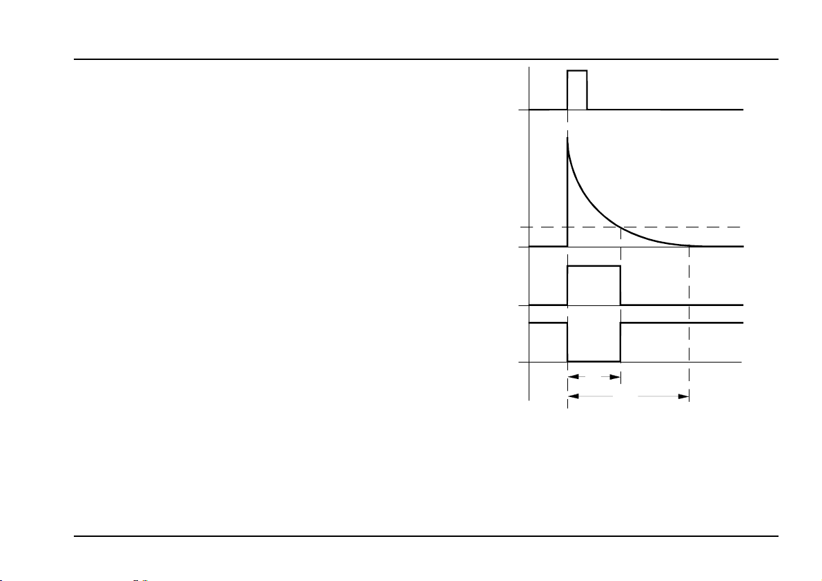
5 Threshold
Control 5 is used for setting the threshold which
determines the
works like this: the gate signal t
when a trigger is sensed, and stops whenever the
envelope voltage falls below the threshold level, which
you set with control 5 (see fig 1).
length of the gate signal
which in turn controls
",
of the
envelope
produced.It
at output $ starts
G
being
Trig In
0 V
Env Out
Threshold
0 V
Gate Out
0 V
Inv. Gate Out
0 V
t
G
t
D
fig. 1: How the A-142 responds to a trigger
Simultaneously, at output % , an
inverted gate signal
is available.
3
Page 4

A-142
Voltage Contr. Decay / Gate
System A - 100
doepfer
4. In- / Outputs
! Trig. In
Socket ! is where the
trigger signal
" CV
Control voltages for the decay time are patched in
here.
The actual decay time t
H
combination of the level of the CVs themselves,
and the positions of decay control 1 and the CV
attenuator 2.
§ Env. Out
Socket § is the output for the
142 produces.
envelope
$ Gate Out • % Inv. Gate Out
The sockets for the
output % respectively.
gate output
is patched in.
is determined by a
D
that the A-
$ and
inverted gate
5. User Examples
Since the A-142 is really a simple envelope, with just
the one parameter to control, ideas for its use can
include any of the occasions on which you might use
the decay characteristics of an A-140 ADSR or A-141
VC-ADSR.
Random-Decay
CV
VCO
Gate
Random
Out
A-1 18
fig. 2: Random-Decay
A-148
VCF
Trig. In
VCA
Trig. In
VCD
CV
The patch in fig. 2 produces a random decay effect, so
that each key played has a percussive envelope of
4
Page 5

doepfer
System A - 100
Voltage Contr. Decay / Gate
A-142
random length
. An interesting variation on this theme
is to patch the output into a filter CV input, so that each
new note has a different filter accent.
Bringing an analogue sequence alive
The same sort of principle is used in the patch in fig. 3,
where a normal note sequence controlled by the A-155
is brought to life by having
different filter accents for
each note.
The upper sequencer row controls the pitch of the
note, and the lower row controls the voltages sent to
the VCD, and thus the different envelopes for each
note.
Voltage-controlled Trigger Delay
In the patch in fig. 4, the gate function of two A-142s is
put to good use. By connecting them in series, and
using the inverted gate output on the first, you can get
voltage-controlled delays of the trigger signal.
The inverted gate output on the first VCD is patched
into the trigger input of the second. You use the trigger
threshold control on the first VCD to determine the
delay time t
signal is controlled by setting the threshold control on
the second VCD (see fig.5).
. The length tT of the delayed trigger
D
Clock
A-155
1 2 3 4 5 6 7 8
VCO
Trig.
In
VCD
CV
Trig. 1
Glide Crt l. 1
Gate
Pre Out 1
Pre Out 2
VCF
VCA
ADSR
fig. 3: "injecting some life into a sequence"
5
Page 6

A-142
Voltage Contr. Decay / Gate
System A - 100
doepfer
Trigger
VCD 1
Trig. In
VCD 2
Trig. In
: voltage-controlled trigger delay
fig. 4
Inv. Gate Out
Gate Out
Delay
This sort of patch for delaying a trigger signal is very
useful, for example, in producing delayed vibrato or
other modulation. For more suggestions of uses, look
at the user examples in the A-162 (Trigger Delay)
manual.
Trig In
VCD 1
0 V
Env Out
VCD 1
Threshold
VCD 1
0 V
Inv. Gate Out
VCD 1
0 V
Env Out
VCD 2
Threshold
VCD 2
0 V
Gate Out
VCD 2
0 V
t
t
T
D
fig. 5: Signals for the voltage-controlled trigger delay
6
Page 7

doepfer
System A - 100
Voltage Contr. Decay / Gate
A-142
7
Page 8

A-142
Voltage Contr. Decay / Gate
System A - 100
6. Patch-Sheet
The following diagrams of the module can help you
recall your own
Patches
complete 19” rack of modules will fit onto an A4
sheet of paper.
. They’re designed so that a
A-142
Trig. In
Volt. Contr. Decay / Gate
VCD
Decay
A-142
Volt. Contr. Decay / Gate
Trig. In
VCD
Decay
doepfer
A-142
Volt. Contr. Decay / Gate
Trig. In
VCD
Decay
Photocopy this page, and cut out the pictures of this
and your other modules. You can then stick them
onto another piece of paper, and create a diagram of
your own system.
Make multiple copies of your composite diagram,
and use them for remembering good patches and
set-ups.
P
• Draw in patchleads with colored pens.
• Draw or write control settings in the
little white circles.
8
CV
Env. Out
Gate Out
Inverse
Gate Out
0
0
Gate
0
Threshold
10
CV
10
10
CV
Env. Out
Gate Out
Inverse
Gate Out
0
0
Gate
0
Threshold
10
CV
10
10
CV
Env. Out
Gate Out
Inverse
Gate Out
0
0
Gate
0
Threshold
10
CV
10
10
 Loading...