

Page 1
doepfer
In 1
In 2
In 3
In 4
Input 1
Input 2
Input 3
Input 4
A-138
MIXER
Output
System A - 100
1. Introduction
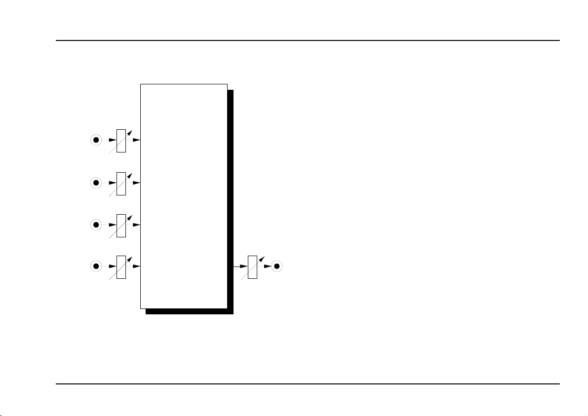
Module A-138 (MIXER) is a four channel mixer, which
can be used with either control voltages or audio signals.
Each of the four inputs has an attenuator, and there’s a
master attenuator, so that the mixer can be used at the
end of the audio chain - ie. it can be used to interface
directly with an external mixer, amplifier, etc..
The module can be supplied in two versions:
•
•
Out
From about middle of 2004 the module is equipped with
an additional offset function for input 1. An internal
jumper is used to decide if control input 1 works as a
positive or negative DC offset generator provided that
no plug is inserted into input 1.
MIXER
A-138 a: potentiometers with linear response, so
especially suitable for control voltage mixing.
A-138 b: potentiometers with logarithmic response,
so especially suitable for audio signal mixing.
A-138
1
Page 2
A-138
MIXER
System A - 100
doepfer
2. MIXER - Overview
A-138
lin
Input 1
0
Input 2
0
Input 3
0
Input 4
0
Output
0
MIXER
exp
In 1
10
In 2
10
In 3
10
In 4
10
Out
10
➀
➁
➂
➃
➄
➅
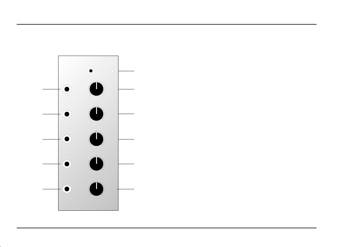
Controls and markings:
1 lin. / exp.: indication of type of mixer:
A-138 a: linear potentiometers
A-138 b: logarithmic potentiometers
2 In 1: Attenuator for input !
3 In 2: Attenuator for input "
4 In 3: Attenuator for input §
In 4: Attenuator for input
5
Out: Output attenuator
6
$
In / Outputs:
Input 1
!
Input 2
"
Input 3
§
$ Input 4
% Output
2
Page 3

doepfer
System A - 100
MIXER
A-138
3. Controls and markings
1
lin. / exp.
Check which little circle is filled in, to see which version,
linear or exponential (logarithmic), the VCA is.
2
In 1 ... 5 In 4
Attenuators 1 to 4 control the level for inputs ! to $.
Out
6
The output level of the mixer is controlled by attenuator 5. Unlike on most A-100 modules, the output has an
attenuator, so that it can act as the end of the audio
chain, and interface directly with a mixing desk, amplifier, etc.
From about middle of 2004 the module is equipped with
an additional offset function for input 1. The pin header
labelled JP4 (located behind input 1 on the pc board) is
used for this option. With no jumper on JP4 the offset
option is disabled. If a jumper is put to JP4 in the right
position (near the edge of the pc board) a positive offset
voltage (~ 0...+5V) is generated by control 1 provided
that no plug is inserted into socket 1. If a jumper is put to
JP4 in the left position (direction to the front panel) a
negative offset voltage (~ 0...-5V) is generated.
4. In / Outputs
!
Input 1 ... $ Input 4
Sockets ! to $ are the mixer’s inputs. Patch in what
you want to mix via these sockets.
H
%
The mixed signal is available at the output.
You can use the mixer for either control voltages or audio signals (see chapter 5, user
examples)
OUT
3
Page 4

A-138
MIXER
System A - 100
doepfer
5. User examples
Mixing audio signals
D Use A-138 b, and patch the audio signals to be
mixed into sockets ! to $.
D Adjust the relative amount of each signal with con-
trols 1 to 4, and the volume of the whole mix with
control 5.
The whole mix is output at socket %.
D
A-138
Input 1
Input 4
MIXER
Out
Output
VCO
In 1
In 4
VCO
Fig. 1: Mixing audio signals with an A-138 b
Mixing control voltages
You may sometimes need more CV inputs than a particular module has - for instance if you want to control
VCF 1 with an ADSR, LFO, aftertouch, and keyboard
tracking.
In that case, you’ll need to use an A-138a VCA to mix at
least two of the CVs, and send the output to one of the
VCF’s free inputs (see Fig. 2).
A-138
Input 1
Input 2
Input 3
Input 4
MIXER
Out
Output
LFO
In 1
In 2
CV
After Touch
In 3
In 4
ADSR
Fig. 2: Mixing control voltages with an A-138 a
4
 Loading...